I’m sure there’s a ton of threads here on this, and I’ve seen YouTube videos, pictures here and there, and lots of other tidbits of info scattered about, but I just wanted to add one more to the list. Feel free to ignore this thread if it’s useless, but I’m hoping it will help someone! If I’m giving bad info here, someone let me know!
Overall, this isn’t a hard job, just tedious. I’m doing it with the engine out of the engine as I’m swapping it into a 5.5 Gen, so the upper oil pan is already removed and I’ll be going from there.
Most stuff I’ve seen in my travels says to replace all three chains, the main tensioner, the top guide, the slack guide, and the two small guides in the camshaft chains. Might as well replace the water pump while you’re in here, too!
I went to my local Nissan dealer and asked them for the parts needed to do this job, and this is what they sold me. They assured me that this is what their technicians replace when they do a 6th gen timing chain job:
13028-ZK01C – CHAIN-CAMSHAFT – Small camshaft chain – Qty 2
13028-ZS70A – CHAIN-CAMSHAFT – Large Crankshaft Chain – Qty 1
13070-7Y000 – TENSIONER ASSY-CHAIN – Main tensioner – Qty 1
13085-7Y000 – GUIDE-CHAIN,TENSION SIDE – Top Chain Guide – Qty 1
13097-ZK01C – TENSIONER FACE – Small tensioner shoe – Qty 2
13510-7Y000 – SEAL-OIL,CRANKSHAFT FRONT – Front seal installed in front timing cover – Qty 1
15066-ZL80A – SEAL O RING – Small o-rings in studs near top left and right of timing cover – Qty 2
I’m not sure why they don’t replace the IVT rings, maybe I can purchase those as well, I’ll add them to the list!
Let’s get started!
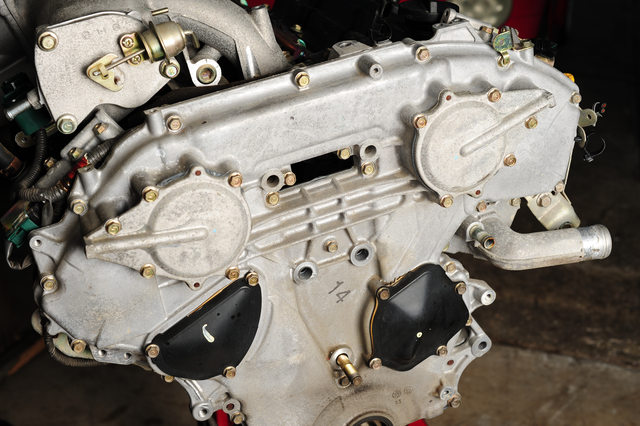
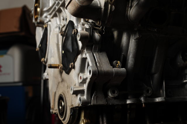
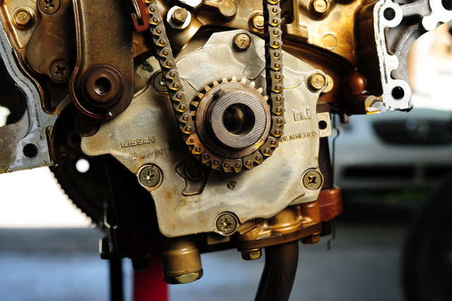
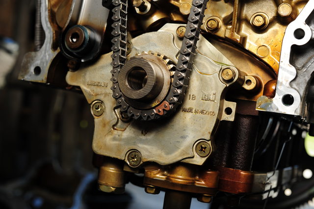
Quick overview of where we’re at here: Front of a 2005 Maxima VQ with 55k miles, this was an AT but that doesn’t matter since the oil pan is already removed. I’m doing this while I’ve got it out of the car so I don’t have to do it again for a long while.
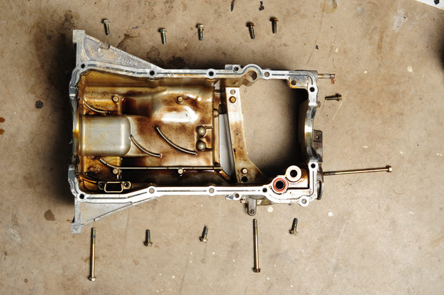
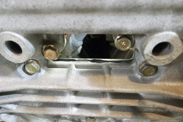
You don’t have to remove the upper oil pan to pull the timing cover, but you DO have to unfasten the two bolts that attach it to the cover. If you don’t, you’ll split your cover when trying to pry it free. This means you must remove the lower oil pan to get to those two bolts. They are the two shown on the right of the image above, the very long one, and the short one.
You’ll also need to have the engine mount bracket removed, in the above picture it’s already taken off.
The problem with the service manual is that it specifies removing everything, including the rear timing cover, so it has you remove a lot of things that are unnecessary, like the valve covers and variable valve timing solenoids. I didn’t remove them to do mine, but you can if you’d like. Just need to get more gaskets and o-rings.
You’ll need to remove the crankshaft bolt if you haven’t already, it’s a bear to pull off since it’s torqued to 36ft-lbs, then rotated another 90°. Plus it’s been there awhile. It took a friend and I to hold the flex plate and run a large breaker bar on it in order to get it loose.
The manual has you remove the IVT covers, which you have to do because they have o-rings and seals inside them. However, you can leave the black water pump and main tensioner covers attached, no reason to remove them since you are removing the entire timing cover.
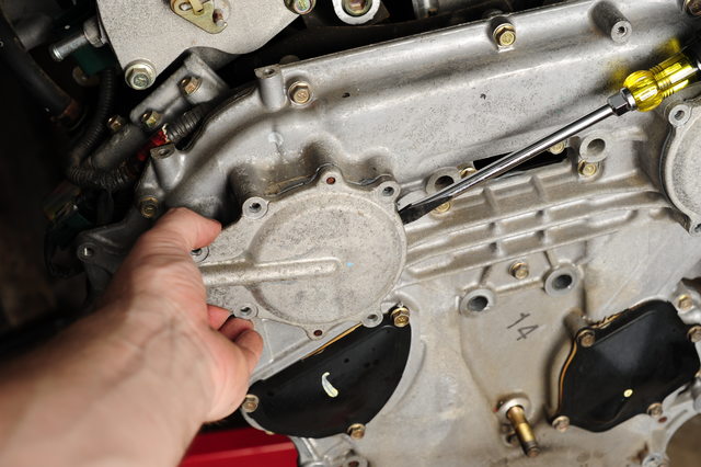
The IVT covers need to be pried off as they’re RTV’d on as well as held in place with o-rings, so I used a large prybar to gently pull one side away enough to slip a large screwdriver in, then wiggled the cover back and forth while gently pushing the screwdriver in further to help pull the cover off straight. At the same time I was cutting around the outside of the cover to help remove RTV, since you’re mainly wanting to be working against the o-rings, not the RTV.
Now that the covers have been removed, the large sprockets are exposed. The main cover can now be removed.
The FSM shows you the proper order in which to remove the bolts so the cover is de-torqued correctly. This may or may not matter, but I followed the guide.
Once all the bolts have been removed, it’s time to pull the case. There are two slots at the top of the case, denoted in the FSM as spots to pry at. These work well for the top, but getting down to the side, it’s more difficult.
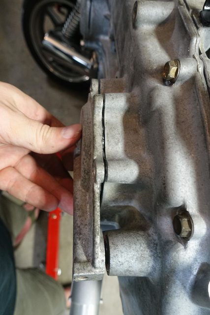
I found a third location to pry at, which seems to work well, and is far enough back from the mating surfaces that it shouldn’t cause marring if you use a screwdriver:
The location just above the bolt hole nearest the camera in the photo is a slot that is exposed even when the cases are stuck together, and should help get them pried apart. Remember to pull it off evenly, and use a knife to cut around the outside should you need to, which may help with the initial prying near the top.
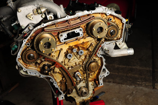
Once that’s off, you’ve got the exposed timing chain area!
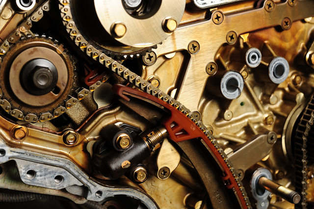
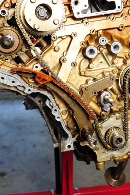
Here’s the main problem, the ‘slack guide’ as Nissan calls it. This part seems to have been engineered with plastic that is too brittle, and too thin near the top, causing it to break off and drop down after some time in the oil.
The part has since been superceded by a newer part, which seems to be made from a different material, as well as having a beefier upper corner.. You can see on the old one where the plastic is already bending away from the metal, this probably would have broken some number of miles down the road.
And here is one of the other tensioner guides you should replace, which may or may not also have worn considerably depending on mileage.
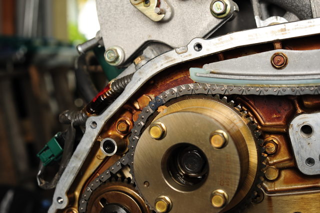
Now that the cover is off and everything is exposed, we can see the chains and the sprockets. Now TDC has to be set on the engine, and an easy way to do that is shown in a few youtube videos as well as here.
Here, I would recommend that you take the time to loosen or break free (NOT REMOVE) the bolts on the four camshafts. These things are torqued to around 76 ft-lbs and have been in there for awhile. It took my 1/2″ impact a few good hits to get them moving, and better to do it now while you’re under tension on an old chain and everything is timed, than to try and do it individually. If you’re removing the valve cover you can ignore and just throw a wrench on the camshaft flats to hold it in place (according to the FSM).
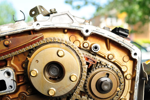
Reinstall the crank drive pulley, or use a large nut as a spacer for the crankshaft, so you don’t bottom out the bolt in the bore when using it to turn the crank. Screw the crank bolt back on and use a breaker bar or large ratchet to turn the 19mm bolt clockwise, until the notches on the large sprockets (intake), and the keyways on the small sprockets (exhaust) are all pointing ‘up’, with respect to the angle of the block on each side.
The small dot punched in the large pulley and the keyway in the small one are both pointing in the same direction. This should be the same for the other side of the engine. The keyway in the crankshaft should be pointing at around 11 o’clock position.
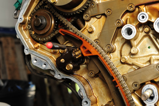
With TDC set, tension can be relieved from the chain. The main tensioner has a small hole in it, and the piston itself has a deep groove near the end of the piston. The piston must be compressed down into the bore enough for the slot to line up with the hole, at which point a ‘suitable tool’ can be inserted. In this case I’m using a small allen wrench, which worked well throughout the repair.
Important!: The small black clip barely visible behind the slot must be squeezed while the tensioner is being compressed. It prevents the tensioner from collapsing back into the bore should the spring or something else fail internally. Squeezing it releases the clamp and allows you to push the tensioner back.
You should be able to compress this by hand since the guide gives you a slight mechanical advantage.
With the tension removed, the tensioner can now be unbolted from the plate and set aside. If you plan to reuse the tensioner, make sure the pin stays in the hole, or the piston may fire out of the bore and leave you with a borked tensioner! If you’re replacing it, the new tensioner should come with a pin already installed in the hole. Leave it in place until you’re completely done with the chain installation.
New (left) old (right):
With the tensioner removed, the chain is now slacked and you can remove the top chain guide (above the camshaft sprockets), slack guide and the chain from the sprockets and water pump. The right guide can also be removed and replaced if desired now.
Next, the small tensioners have to be compressed.
I used a small squeeze clamp to do the job, which worked very well, and since you can’t put a ton of torque into them, which prevented me from breaking something like a screw clamp might. I clamped between the chain and the back of the tensioner, then inserted a small tool into the hole. It didn’t go as deep in these as the main tensioner, but still held. I then released the clamp and made sure the tensioner stayed compressed. Make sure not to bump the tool while you’re working!
Next it’s time to remove the camshaft sprockets and chain.
Remove the bolts holding the camshaft sprockets in place, and make sure you note they are different sizes, the longer one goes into the larger sprocket.
The chain should come off along with the two sprockets. Make sure to note their orientation. The right and left banks are using different markings; facing the timing cover, the left bank uses dots, and the right bank uses slots.
Although you may be able to get the chain off without removing the exhaust (small) sprocket, depending on the wear of the tensioner, it will have to come off in order to get the new chain on.
With the sprockets and chain removed from one side at a time (so you don’t get them mixed up!) The guide can now be removed. This is quite difficult, it’s a snap-fit and it really didn’t want to let go. I ended up using a screwdriver to pry the guide off while pushing inwards on my makeshift pin to make sure it didn’t pop out, and finally got it free.
I used the same technique I used to compress the tensioner to install the new guide. It’s pretty tough to get them on, so the clamp helped a lot. I made sure to hold that pin in place while doing it to both keep the plunger from popping out, but also from sliding all the way in instead of clicking into the guide.
Repeat for the other side, and then we can reinstall the camshaft sprockets and chains.
Now that the guides for the camshaft tensioners have been installed, the chains and sprockets can be installed.
(Quick note here though, this is a good time to get in there and scrape off all that RTV from the face of the timing cover, as the chains aren’t here to get in your way, or get all dirty from flecks of RTV falling into them! I took this time to clean the face up nice and neat.)
First, the new chain should have 3 colored links.. Two right next to each other, and one opposite them.
The single link goes to the dot or slot (depending on left or right bank) on the large sprocket, and the two small go onto the small sprocket’s dots or slots.
First, line up the large sprocket, since it’s on the backside and won’t be visible when installing.
Next, line up the two marks on the front of the small sprocket. Once aligned, you can carefully side them back on, which may take a bit of work with the new, non-worn tensioner and new, slightly-tighter chain.
The old chains’ colored links may be hard to see, and may or may not be lined up correctly, due to what position the engine was in. As long as you line up the new chain’s links though, that’s what counts. Install the same as the other side, ensuring the sprockets are seated completely and the chain is in the center of the tensioner guide.
On my engine, I opted to replace the water pump as well, as preventative maintenance even though there was only 55k on it.
A helpful hint here.. The block still contains coolant in it, even if you’ve drained the radiator and removed the oil cooler. There’s a little drain bolt that lives beside the water pump to help drain the remainder of the coolant from the engine, unscrew it before you do the water pump and you’ll prevent a mess!
It’s the small bolt in the center of that triangle in the middle of the photo.
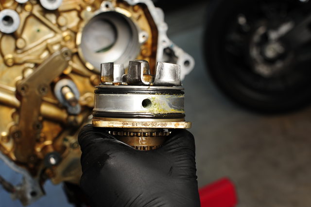
I removed the three 10mm bolts holding the water pump in place. I then pried it out using a large prybar on the forward set of sprocket teeth, so my bar would not pry against the water pump housing itself.
It appears on my pump that the seal was leaking slightly. The area between the two rings is an area connected to a ‘weep hole’, which allows oil or water that begin to leak past to exit the engine through an opening in the block, rather than contaminate each other. In this instance, it appears coolant has been leaking through one ring, so this was a good thing to replace. The center hole is for coolant or oil leaking through the shaft seal to be able to drain down to the weep hole as well.
With the water pump installed, it’s now time to install the large timing chain.
The chain has three colored links, two blue-ish and one copper. The copper link goes to the slot opposite the keyway on the crank sprocket…
And the blue-ish links each are positioned to the dot on each of the large sprockets.
Once the chain is installed and settled properly along all the sprockets, including the water pump, the upper guide can be installed, followed by the slack guide and tensioner.
I found it easiest to install the lower bolt of the tensioner, and swivel it up against the slack guide, as there is still a bit of tension after the upper guide is installed. Pushing firmly on the chain will rotate one of the camshafts to give you a bit more room. Install the bolts and torque to spec.
Once the guides are all installed and torqued, and the tensioner ready, the chain correctly set to the timing marks, and everything looks good.. you can then release the tensioner. Pull on the slack guide a bit while pulling the pin, and the tension piston should take up the slack in the system.
It’s a good idea to snug up the camshaft gears at this point, reinstall the crankshaft pulley or your spacer, and use the crankshaft bolt to spin the engine slowly. You shouldn’t encounter any stiff resistance. If you didn’t pull the plugs, there will be some air resistance, but that will lessen as you hold the crankshaft in that position, and you can continue to turn it. If at some point you can’t turn it at all, and it feels locked in position, that’s bad, and could be valves hitting pistons.. recheck all the timing marks.
This is when I torqued down the camshaft bolts (Don’t forget!). They’re quite difficult to torque when the engine is out of the car; I had to use a prybar in the flex plate gear to hold the crankshaft steady while torquing them.
Once they’re torqued up, you should be good to go. Make sure you torqued all the bolts holding the water pump and chain guides to the specs in the FSM.
Done!
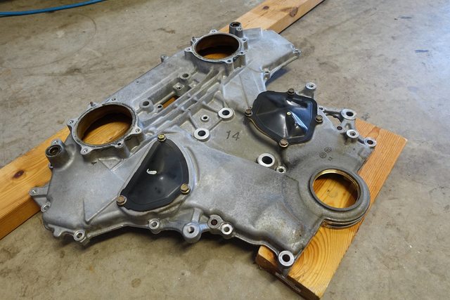
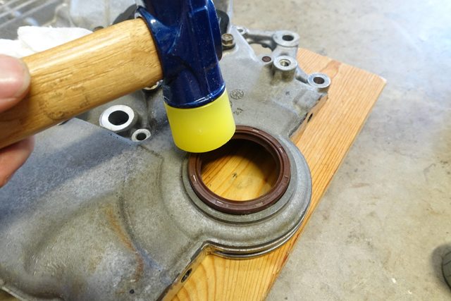
I took the opportunity to set up the cover on a couple of blocks, pry out the old front seal and replace it with a new one.
I used a soft mallet to very slowly and gently tap in the new seal, along with a bit of oil to make sure it slid in nicely. A block of wood would also work, if you don’t have a soft hammer.
I wiped all the mating surfaces down with isopropyl alcohol, and used my compressor to blow all of them off to make sure I wasn’t leaving any pieces of RTV left on the covers.
Unfortunately, I don’t have any photos of putting RTV on the main cover, but it’s fairly straight forward. I used Permatex Ultra Black RTV sealant, and deviated from the FSM slightly in the technique.
While the FSM calls for applying the silicone, installing and tightening the cover, the RTV bottle says to apply the bead, install the cover with bolts finger tightened just until it starts to ooze out from the mating surfaces, then let it set up for one hour. After that, complete the torquing process. I can understand why this is, as the RTV will cure a bit before being deformed into the final shape.. It will also provide the pressure against it necessary to prevent any leaks. I used the method printed on the RTV.
Now, you may need to also clean up and install the front oil pan seal at this point as well, if you did not remove the oil pan. Since my upper oil pan is already removed pending a swap, I didn’t have to worry about this, but if you did not remove it and only unbolted, then you’ll need to reinstall the oil pan seal, and most likely RTV in the spots specified by the FSM, and/or where you saw the RTV originally placed from the factory.
For the initial tightening, this is what I saw at the cracks:
I let it set up for one hour, then torqued all the bolts down to the specified torque, in the specified order:
After taking care of that, I began to RTV the other covers, installing them one by one, cleaning them in the same way as the main cover.
Fully RTV’d main cover
Installing the cover, making sure the dowel pins line up and it’s being pushed in straight. I also oiled the plastic seals on the lid that slide into the intake camshafts.
You can see a slight squish as the RTV is compressed.
After gently snugging up the bolts with just fingers on a socket
After waiting another hour, I torqued down the bolts to their spec, in the order the FSM specifies.
Seafoam is a 100% pure petroleum product for use in all gasoline and diesel type engines, both 2 and 4 cycle. OXYGEN SENSOR SAFE. Cleans dirty engine parts internally by removing harmful gums, varnish and carbon. WORKS AND PERFORMS INSTANTLY.
Removes moisture from oil crankcases and fuel tanks.
Stabilizes and conditions fuels. Use for engine storage.
Cure hesitations, stalls, pings and rough idle due to carbon buildup.
Helps pass emissions test. EPA Registered.
Important Note: Run the seafoam in your oil for NO MORE THAN 250 miles! Seafoam is very aggressive. Your next oil change will be black as satan’s heart and likely thicker than usual. I would not recommend running this oil very long in the car as your oil filter is going to have quite the time on its hands and the oil won’t be in the best of shape afterwards. I’ll say it again. change your oil less than 250 miles after you put seafoam in your crankcase! I recommend running it 100 miles, then changing your oil. that should be plenty for the seafoam to get most of the gunk out.
How to change your Cabin Air Filter
IMPORTANT NOTE: The in cabin air flow is TOP to Bottom, in the Video I incorrectly stated the direction of the arrow should point for an aftermarket filter! If using a NISSAN Filter they show an arrow in the middle of the filter stating this side up while off to the right of the filter it shows and arrow pointing down stating direction of Air Flow. For an aftermarket filter it has an arrow in the middle which shows an arrow with the direction of air flow so for aftermarket filters the filter needs to be turned over and the arrow face down. It won’t break anything so don’t freak out just wanted to point out the difference.
Are you noticing a lack of power when accelerating between 0-40 MPH? Is your car fine once you get passed 40 MPH? Did you scan for codes and nothing? Do you have a CVT?
If you answered YES to the questions above, then you may be experiencing a common issue on the CVT Nissan Maxima where you have a faulty ABS/VDC wheel speed sensor. Nissan has published Service Bulletin NTB11-089 to address this issue on the 2007-2012 Nissan Maxima.
You may think that your CVT is going bad? However, many have had their CVT transmissions replaced and still had the same problem. Start by checking your ABS/VDC wheel speed sensors first.
You can download the Service Bulletin by clicking the link below in case you want to show it to your Nissan Dealer or Mechanic.
The most likely cause of the above concern is an issue (sensor, wiring, or debris on sensor/rotor) with the output signal from an ABS/VDC wheel speed sensor.
A weak or erratic output signal from a wheel speed sensor can cause poor performance or lack of power from a stop, or at low speeds.
Do not replace the TCM or CVT unit when repair of a signal from a wheel speed sensor will resolve the issue.
How to Fix it?
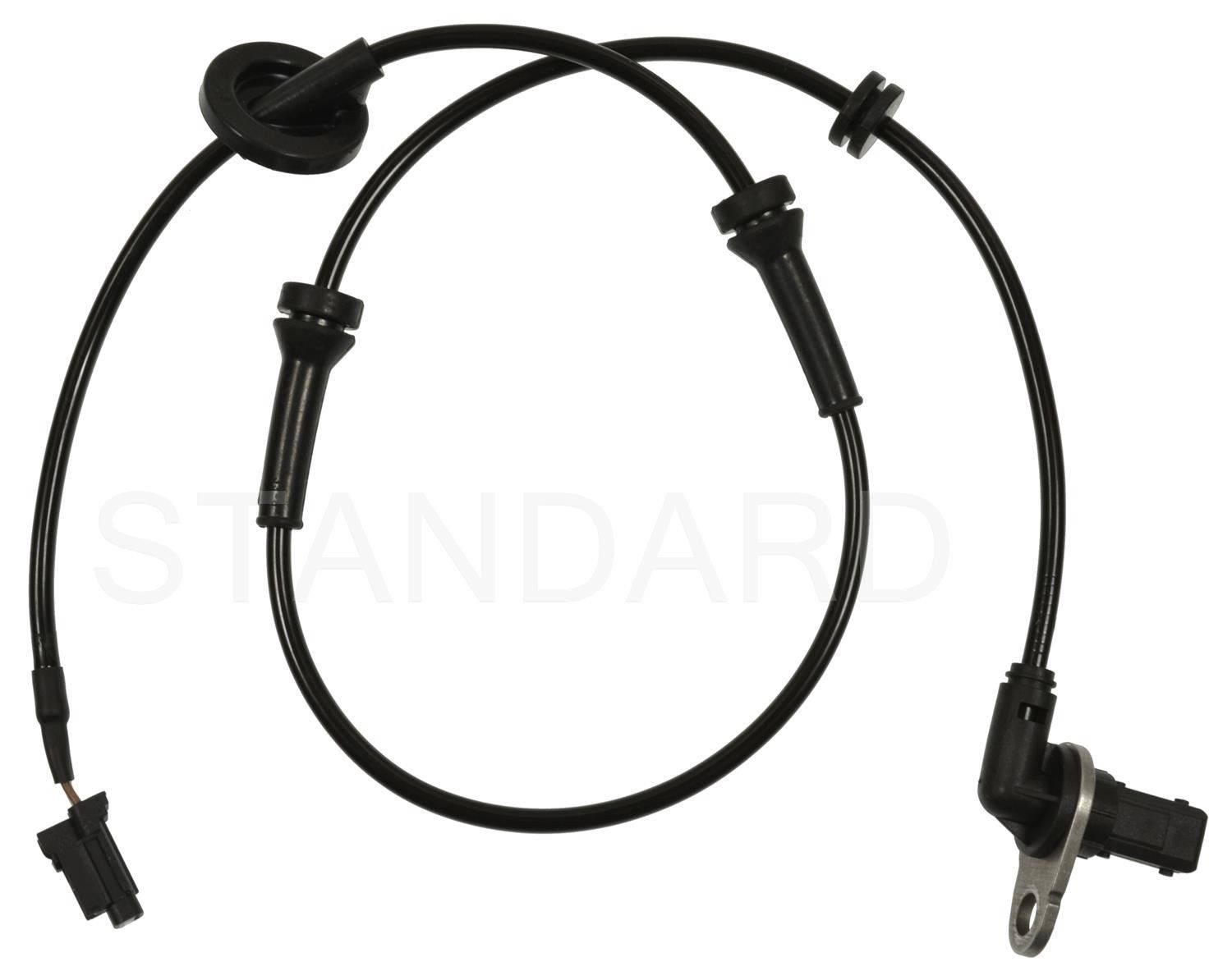
Inspect and replace the ABS Wheel Speed Sensors. You may not need to do them all, but the sensors are fairly inexpensive. You have two options, Dealer or eBay. Seems like many folks have have had success with the eBay ones and you can get all four for $50 bucks shipped. Yeap that’s right ALL FOUR!
However, for all electrical parts we always recommend OEM.
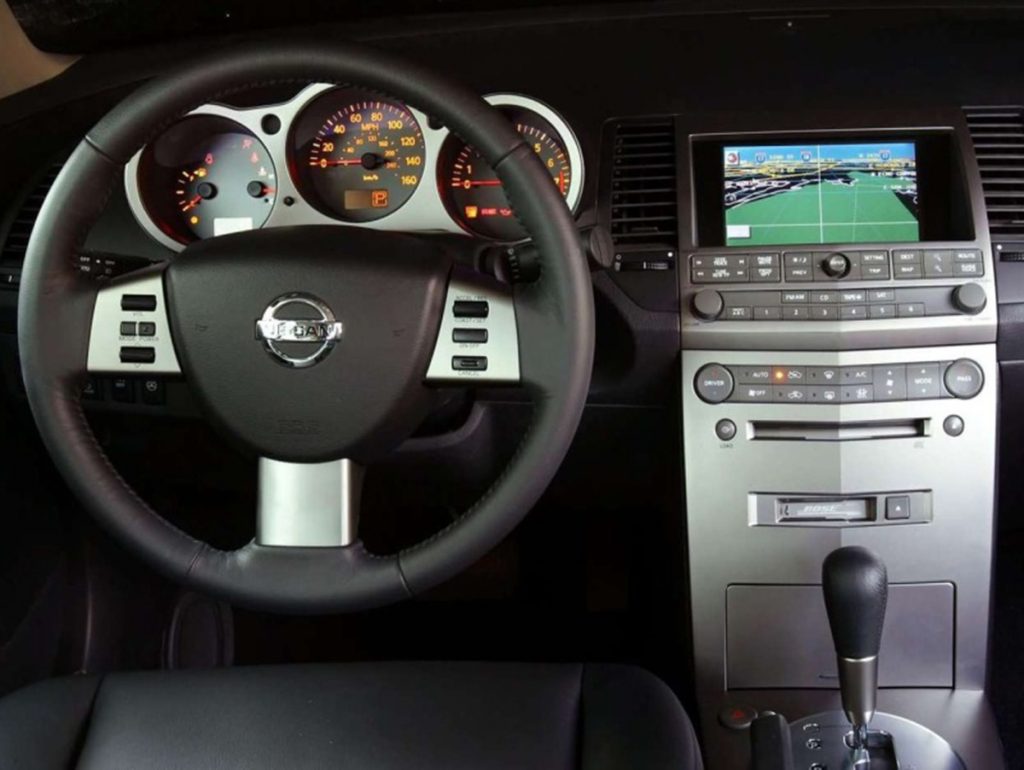
Press the “Maintenance” button below the “Navigation Screen”. Once you’re at the “Oil Change” screen, hold the “Trip Reset” button for a few seconds and it will reset itself.
Do this when you are parked and not in motion because it won’t let you reset it.
Some people usually set this alert off. In the maintenance screen you can set service alert on/off. If the service alert .ON. key is selected, the information will be displayed when the engine oil and the tire rotation periods reach the preset driving distance.
Also note you can set your oil change intervals. You adjust higher or lower using the left and right buttons but most people keep at 3K.
You can see all these features through your maintenance screen.
Note:This is the button on your rear view mirror is you have this function.
To program your HomeLink Transceiver to operate a garage door, gate, or entry door opener, home or office lighting, you need to be at the same location as the device.
Note: Garage door openers (manufactured after 1996) have “rolling code protection”. To program a garage door opener equipped with “rolling code protection”…you will need to use a ladder to get up to the garage door opener motor to be able to access the “smart or learn” program button.
1. To begin, press and hold the 2 outer HomeLink buttons (to clear the memory) until the indicator light blinks slowly (after 20 seconds). Release both buttons.
2. Position the end of the hand-held transmitter 1-3 inches away from the HomeLink surface.
3. Using both hands, simultaneously press and hold both the HomeLink button you want to program and the hand-held transmitter button. DO NOT release the buttons until step 4 has been completed.
4. Hold down both buttons until the indicator light on the HomeLink flashes, changing from a “slow blink” to a “rapidly flashing blink”. This could take up to 90 seconds. When the indicator light flashes rapidly, both
buttons may be released. The rapidly flashing light indicates successful programming. To activate the garage door or other programmed device, press and hold the programmed HomeLink button – releasing when the device begins to activate.
5. If the indicator light on the HomeLink blinks rapidly for two seconds and then turns solid, HomeLink has picked up a “rolling code” garage door opener signal. You will need to proceed with the next steps to train the HomeLink to complete the programming which may require a ladder and another person for convenience.
6. Press and release the “smart” or “learn” program button located on the garage door opener’s motor to activate the “training mode”. This button is usually located near the antenna wire that hangs down from the motor. If the wire originates from under a light lens, you will need to remove the lens to access the program button.
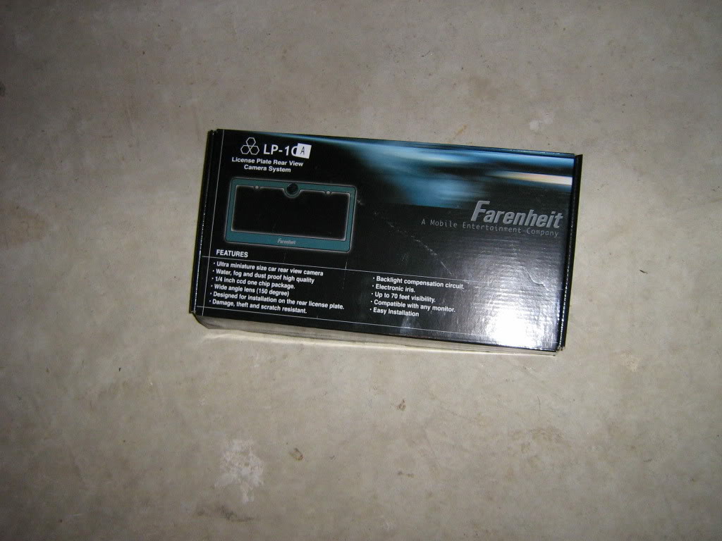
So it was spring cleaning at the stereo shop I work at part time and I noticed a box I know I had seen at least twenty times before but never read. Whoa its a Farenheit rear view camera. SNATCHED (with permission of course). I already have the interior out of the car because I’m upgrading my sub and amplifiers so that just makes it easier to route the wires. Now the pics:
*ADDED – Camera model # – Farenheit LP-1CA
The rear view view camera -itself
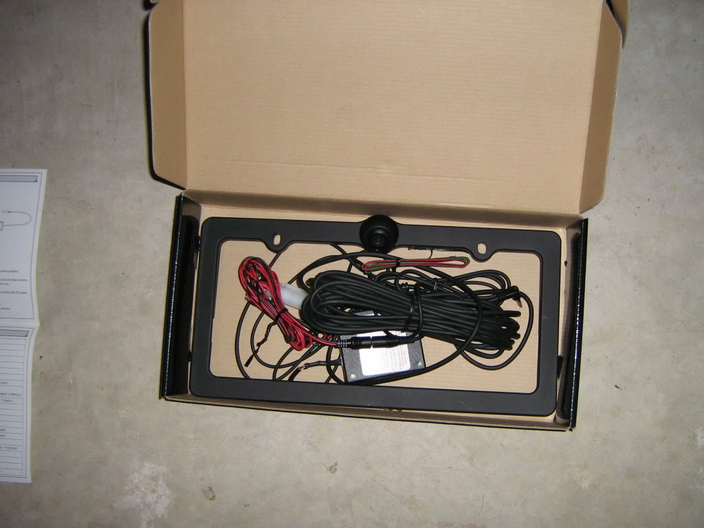
2. The contents of the box
3. The contents sorted on the floor
4. Removed plate and old license plate holder
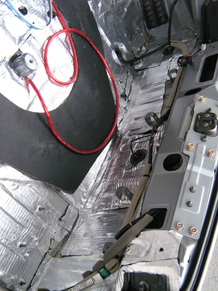
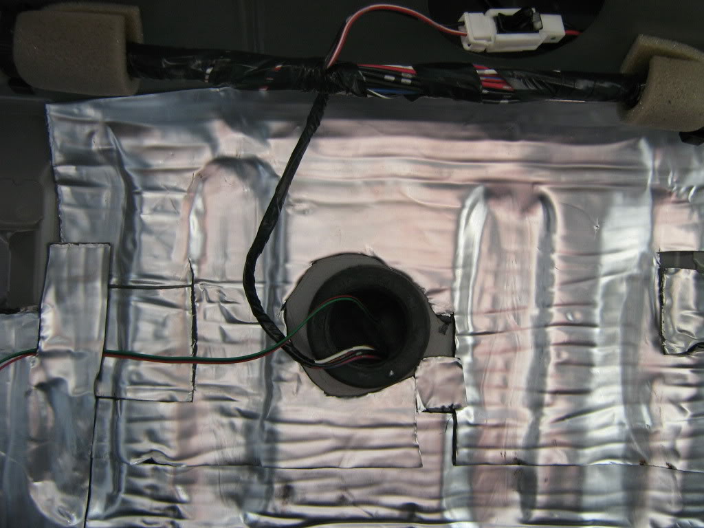
5. The inside of the rear, notice the large grommit in the center. This is where I ran the wire inside the car
6. Once the grommit is removed, you can cut a small slice in it to run the wires through
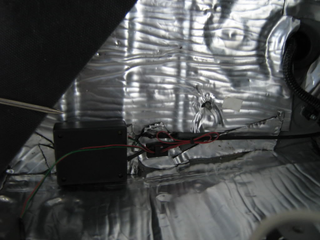
7. Once the wire from the frame is inside the car, it must be connected to a small box that was included with the frame. the image processing is done inside this box and then images are sent from the box to your headunit. Be sure to tuck it away so it doesn’t get crushed.
8. Reverse wire. Dont forget the reverse wire. Without this connection the Avic Z1 wont switch to rear camera when you shift into reverse. Pioneer included a specific wire for this connection so I tapped into the reverse light in the rear as opposed to finding the wire up front.
9. Once the wires is tapped it’s time for a little wire management.
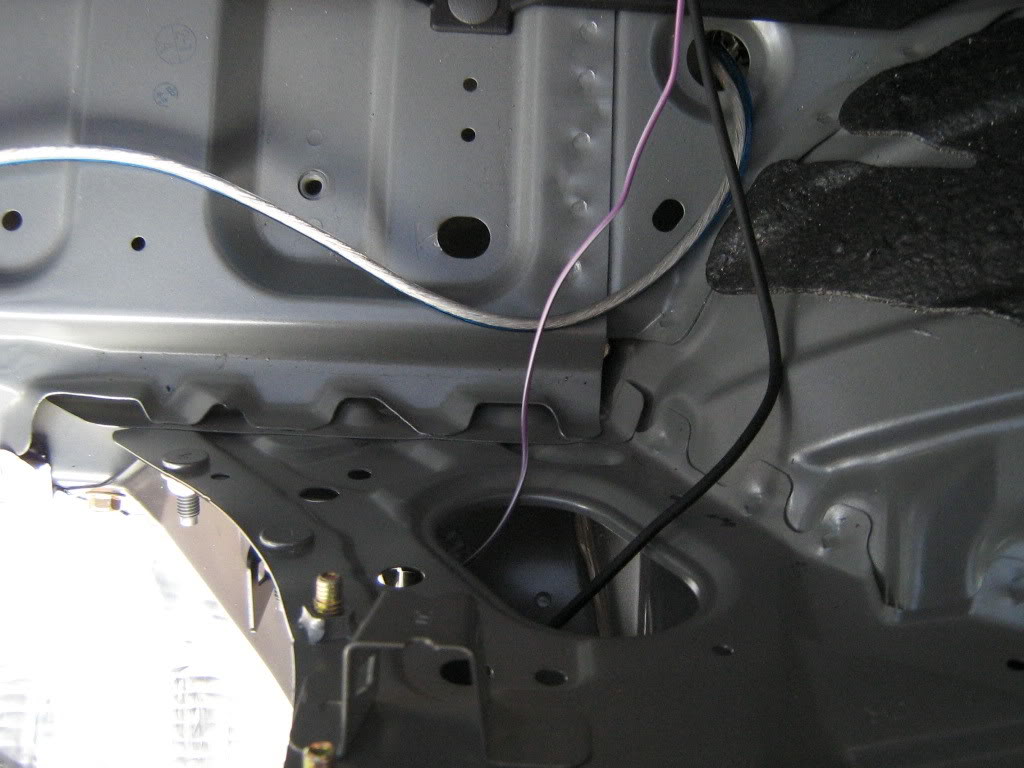
10. Through the rear strut bar and out the compartment behind the passenger seat.
11. I ran the wires down the center, its a lot easier then pulling up the carpet. Time for the Z1 to come out again.
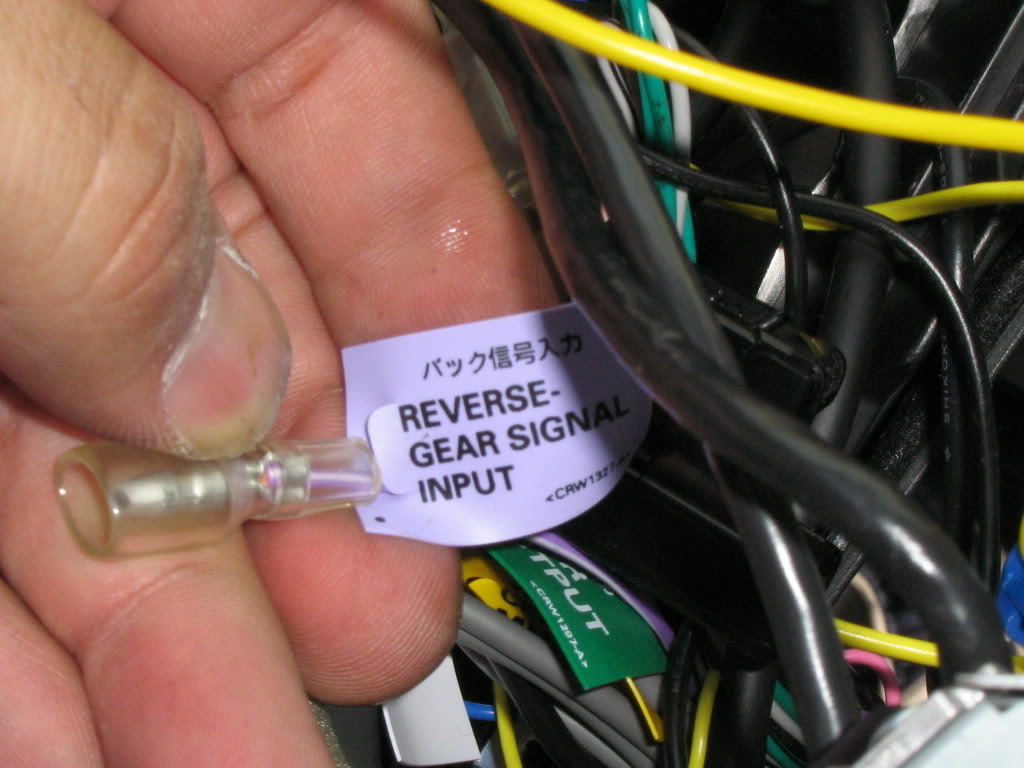
12. Find the wire for the reverse gear input and connect it to the wire that you tapped into the reverse light in the back.
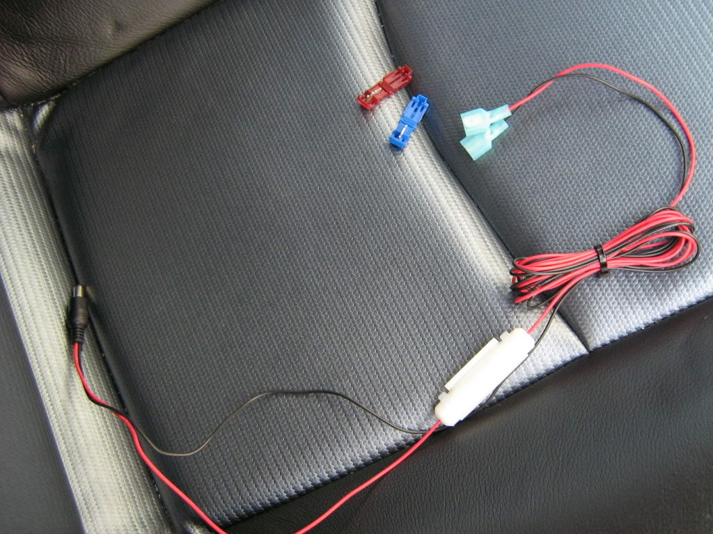
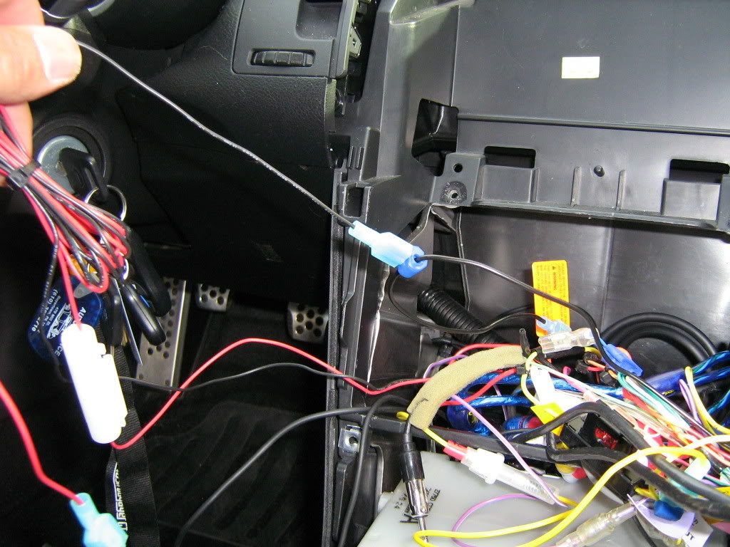
13. Time to tap into some power for the camera. It doesnt really matter where you tap into the power, but since this camera has the power wires attached on the end of the cables that get attached to the head unit, I tapped the constant power from the head unit and the oem ground. The headunit has its own separate ground now. Here is a shot of the power wire prepped for install
14. The last connection, the actual video feed from the box mounted in the rear.
15. Turn on the car and test it out before securing down the head unit. Make sure all of your speakers and devices attached to the radio are functioning. It gets really tight behind the head unit and its easy to disconnect wires when reassembling. I had to change a setting on the headunit to accept camera feed for the rear.
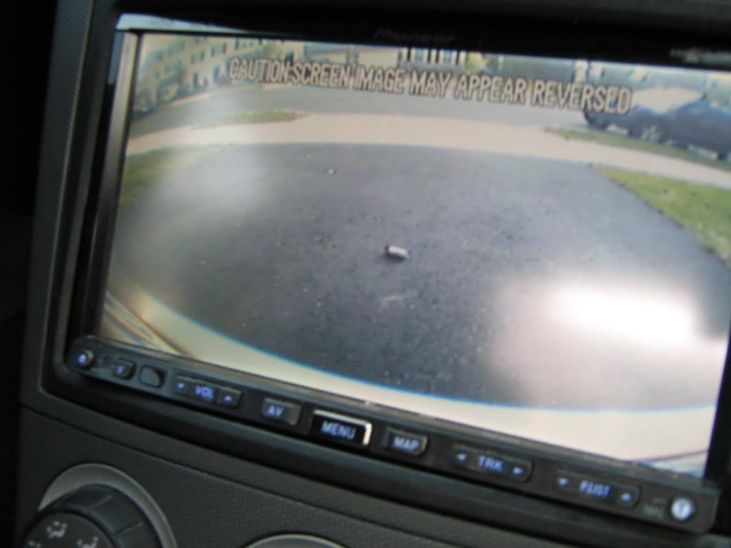
Here are some pics of the images from the camera
With old school cheap a$$ pager on the ground for scale
with some needle nose pliers
From the side
The finished product
Enjoy.
BTW since the license plate camera frame is substantially thicker then your average frame, I had to replace the screws and the mounting clips. When I bought the car the stealership used some horrible little screws that stripped the nuts inside the oem clips. A quick trip to lowes for two new coarse thread phillips head bolts, two body clips and two plastic black screw caps did the trick.
Tools Needed:
– New Updated DVD
– Flathead Screwdriver (or knife)
Step 1:
– Its easiest to access the DVD player if the car is in Neutral so put the car in neutral and place the E-Brake.
Step 2:
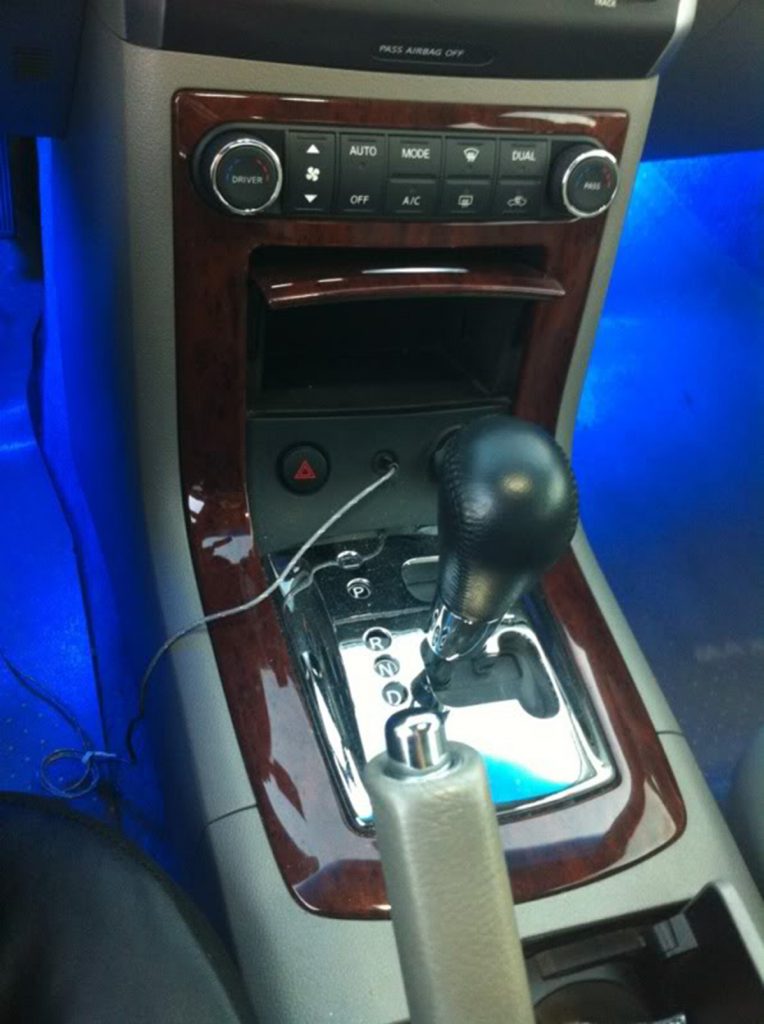
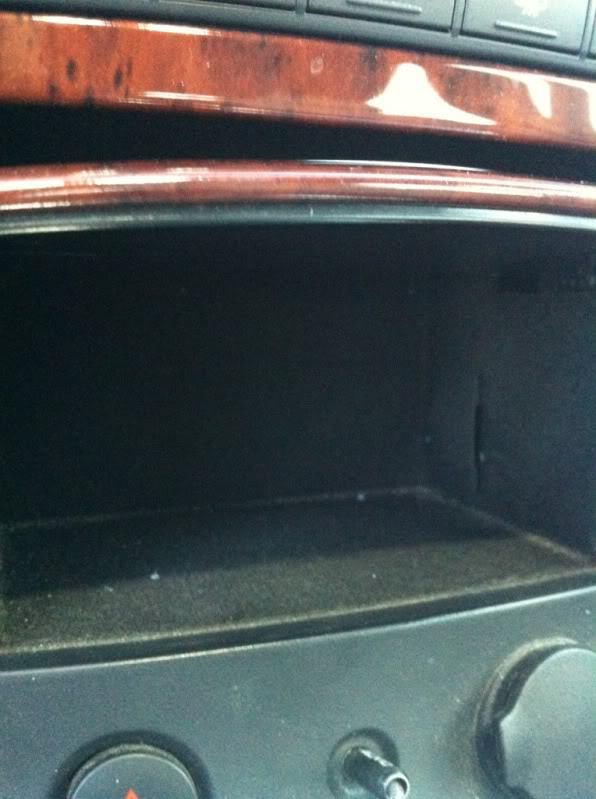
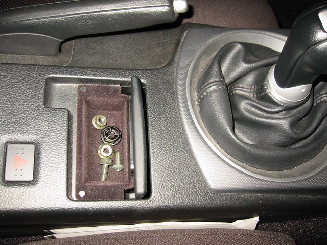
– Open up the small door in front of the shifter. You will see black felt lining.
Step 3:
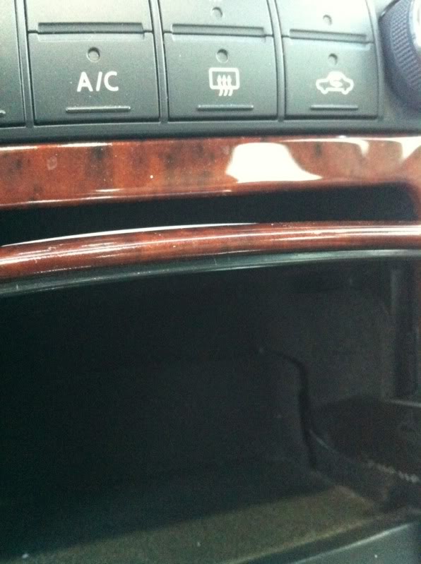
– Shine a light into the storage area and you will see there is a small notch on the pass side wall of the storage area. Place your flathead screwdriver (or knife) into that slot and pry towards you GENTLY. The door will pop out towards you.
Step 4:
– Make sure your car is in ACC mode and then hit the eject button on the DVD player. Remove DVD.
Step 5:
– Insert the Updated DVD into the drive. The Navigation screen will display “loading”. Then it will bring up your map!
Step 6:
– Replace the small felt door and you are all done!!
Also, for 04-05’s, The update DVD you need currently is Version 6.9. It is the update for 2010-2011 Map Update. For 06-08’s you need version 7.7. These are the 2011-2012 Map Update years.
The pictures are from a 350z but you can see its just about the same exact procedure for a 6thgen.
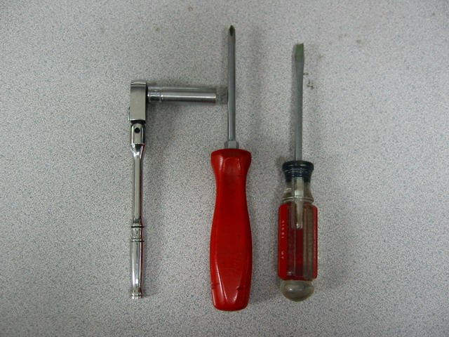
Tools required for ECU removal and re-installing.
1. 10 mm socket and ratchet (or equivalent)
2. Philip (cross) screw driver
3. Flat head screw driver
Before you start lower your driver and passenger side window down about 1-2 inches. You can lower it more, but at the very minimum 1-2 inches. This is done so when you disconnect your battery the doors will open smoothly.
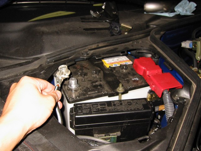
Start by disconnecting the battery by removing the negative terminal using the 10 mm socket.
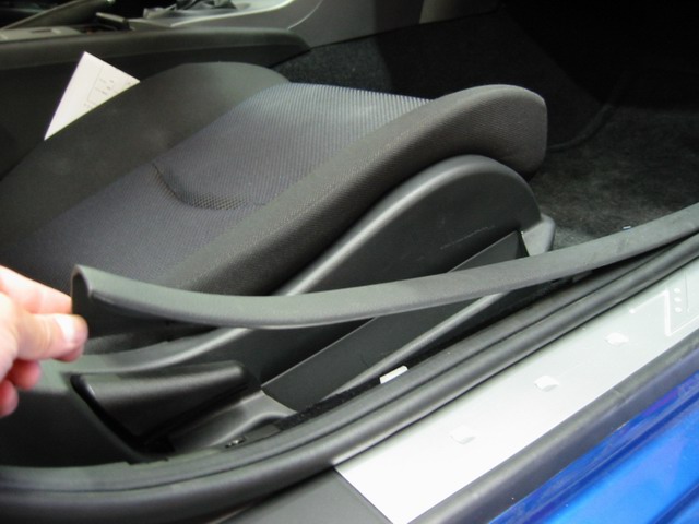
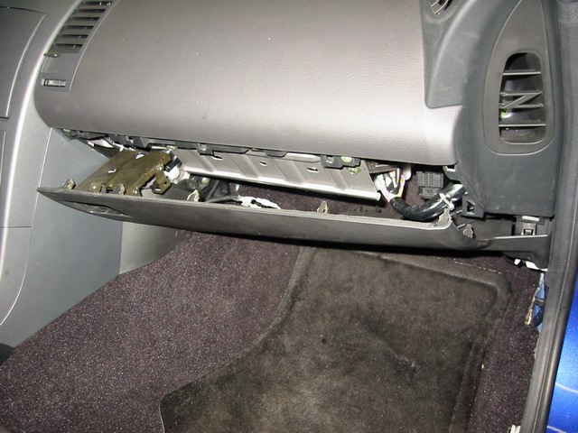
Next open up the passenger side door and remove the floor/doortrim by gently pulling upwards. Start from the rear and work towards the front.
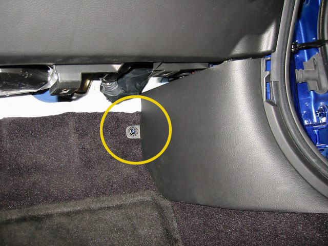
Find the plastic nut that holds the side kick panel. Remove it by turning counter-clockwise. No tools are needed. It’s not on very tight. Put all loose hardware (nuts, bolts) into the tray behind the shifter.
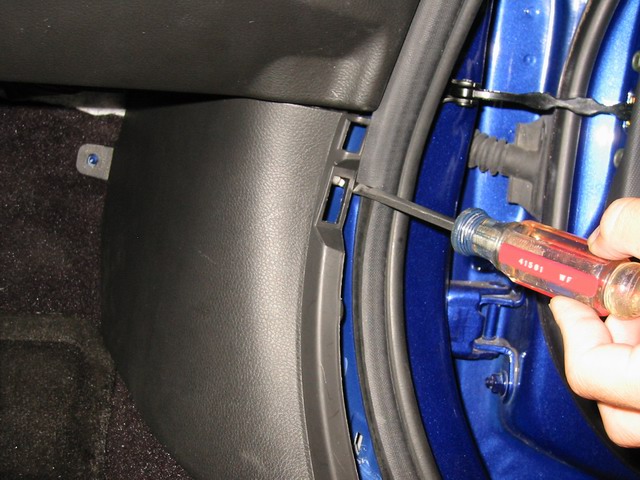
Use the flat head screw driver (if need) and pry the front edge of theside kick panel outwards (towards the driver side) and remove the panel. Be careful of where you put the screwdriver. It CAN break the plastic.
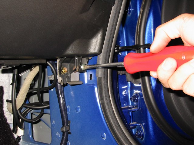
Locate the screw under the kick panel. Use the philips (cross) screwdriver to remove it. You DO NOT need to remove the 10 mm nut.
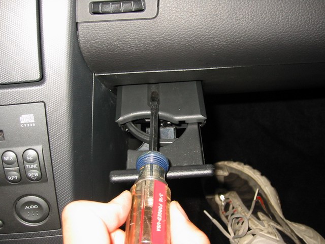
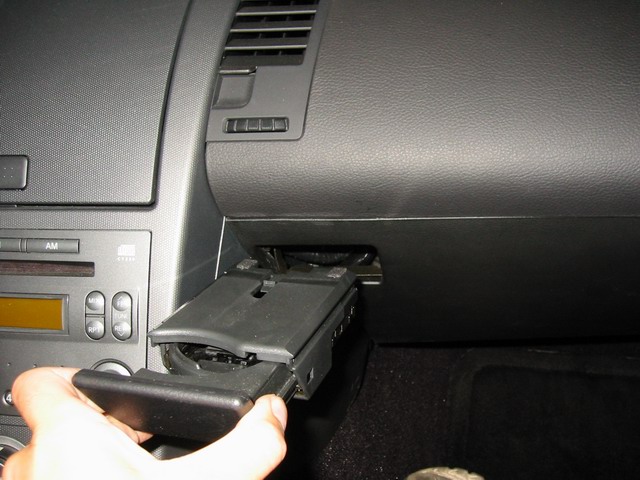
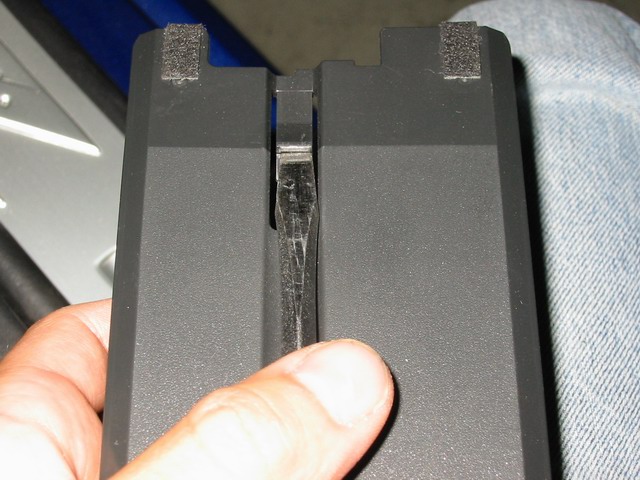
Now pull out the cup holder in the dash area and insert the flat screw driver into it. Gently pry downward on the inner clip and pull out the cup holder. The clip is extremely hard to see, trust me it’s there. (See pictures below.)
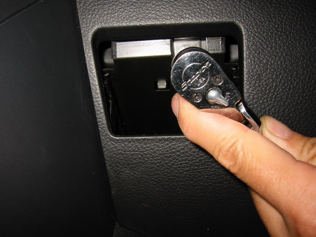
Hidden behind the cup holder is a 10 mm bolt. Remove it with the10mm socket and ratchet.
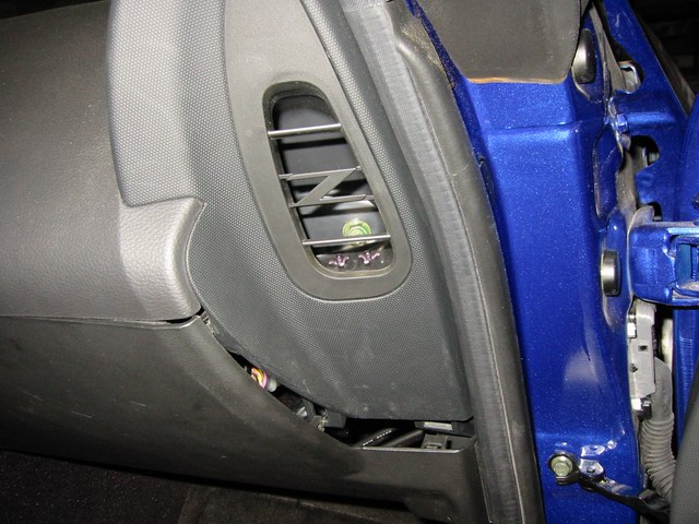
Start from the bottom right corner and pull out the sub-dash panel. It is held on by several clips. Work your way counter-clockwise until all clips are pulled out of their holders. The panel drops down and pulls out.
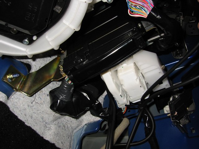
Look up underneath the dash and you will now see the 350Z’s ECU (Engine Control Unit).
To disconnect the harness from the ECU,simply squeeze the tab together (at the end of the connector) and gently pull it down and over. The connector will unhook itself. Pull the connector down and leave it hanging.
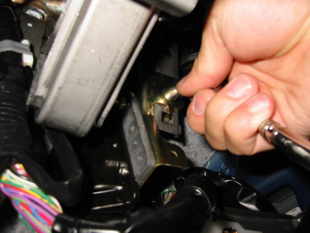
There are now 2 more nuts remaining until the ECU comes out. Look up towards the ECU and you will see a 10mm nut and another one towards the firewall. Remove them and put the nuts in the tray behind the shifter. (Pictures below)
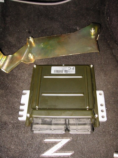
The ECU should come down easily with the bracket. Remove the bracket from the ECU and put all the nuts back onto the bracket. The ECU is now ready to be sent in for Flash Programming.
These are all the parts you should have left over for the removal of the ECU.
Installation is in the reverse order. After the ECU and all panels are installed. There is no need to reset the ECU.
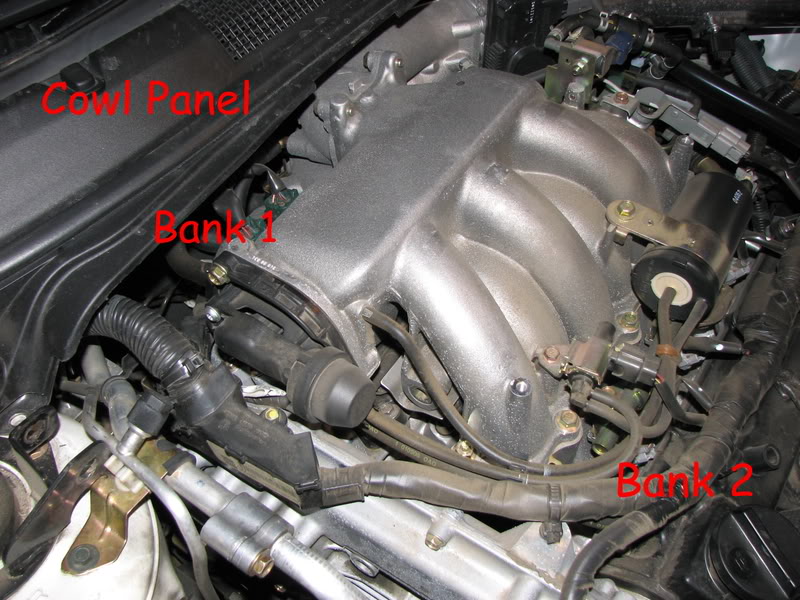
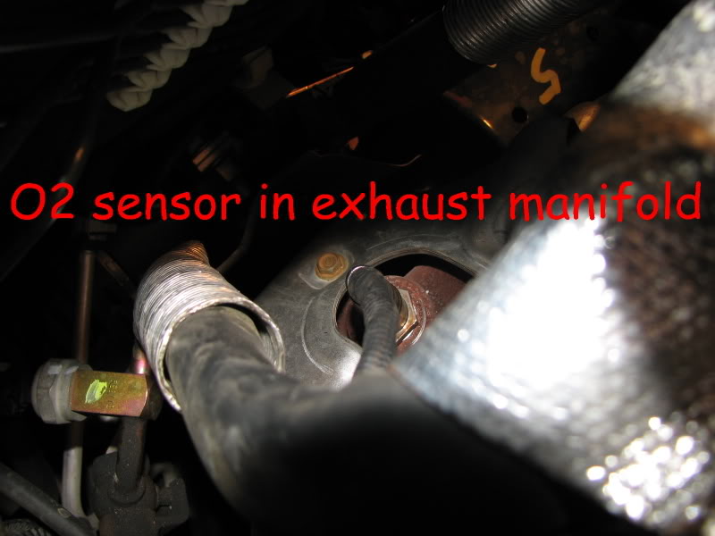
My SES light came on the other day and the code is indicating O2 sensor Bank 1, Sensor 1. That is the bank that is on the back side of the engine, against the firewall. Sensor 1 is the sensor in the exhaust manifold before the cat.
BTW… I priced this sensor at the various auto parts dealers and found the following:
Obviously I was looking for the exact replacement and not a universal fit that I was going to have to splice wires on. Autozone, Advance and Napa all listed the exact same Bosch part number (17264) but their prices varied by nearly $100!
I ordered mine from Napa but after a week they said they were out of stock and so was the manufacturer (Bosch). Advance Auto and Autozone both gave me the same information. Sadly, I had to break down and purchase the sensor from the stealership.
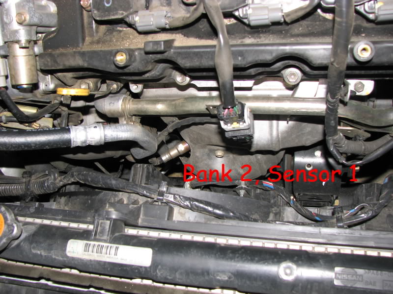
My SES light came on and the code indicated Bank 1, Sensor 1. Bank 1 is the side of the engine closest to the firewall. Bank 2 is on the front, closest to the radiator.
Sensor 1 is in the exhaust manifold, before the cat. Sensor 2 would be after the cat.
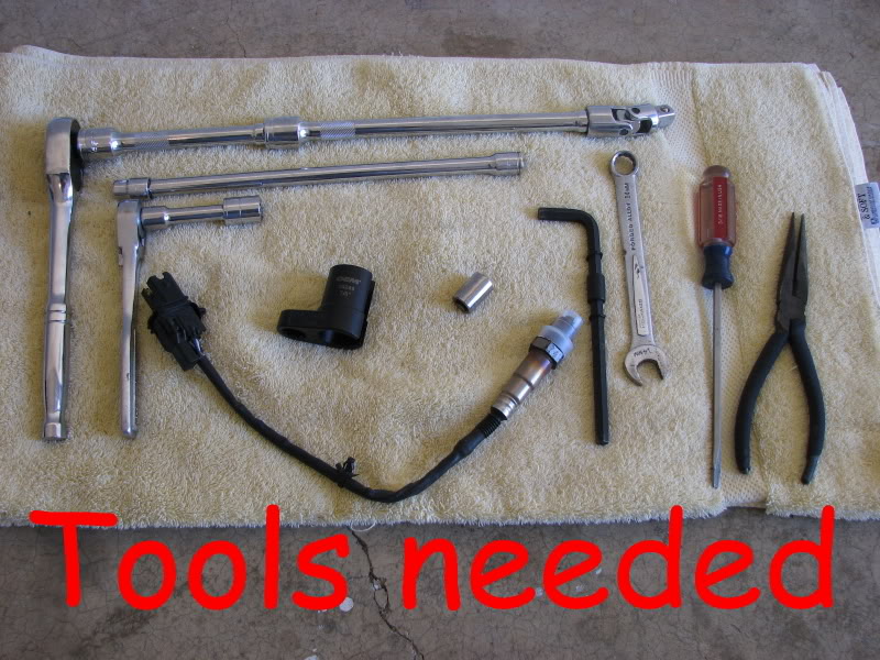
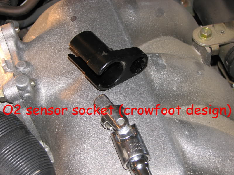
To do the job, you will need a few simple hand tools including a ratchet with extensions, 10mm, 12mm and 14mm sockets, a standard screwdriver, needlenose pliers, and an O2 sensor socket. I used a crowsfoot design O2 sensor socket because a straight O2 socket was not deep enough. If you have a strut tower bar like I have, you will need an allen wrench and 14mm wrench to remove that.
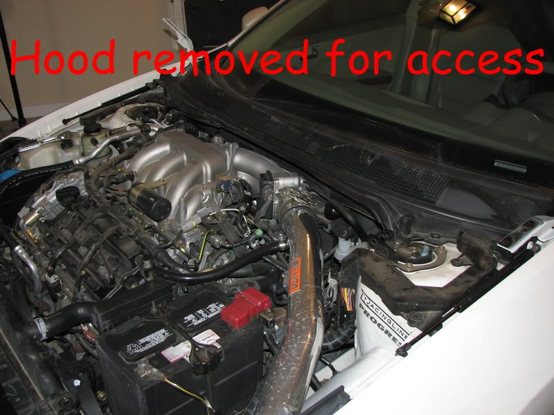
Again, as I stated, my bad sensor was in the bank 1 exhaust manifold. In order to gain access, I had to remove the hood, strut tower bar, windshield wiper arms, plastic cowl panel and metal cowl panel.
When removing the hood, have someone assist you in lifting it off. It is a good idea to mark your hinges with a paint pen so you can align the hood properly when reinstalling it.
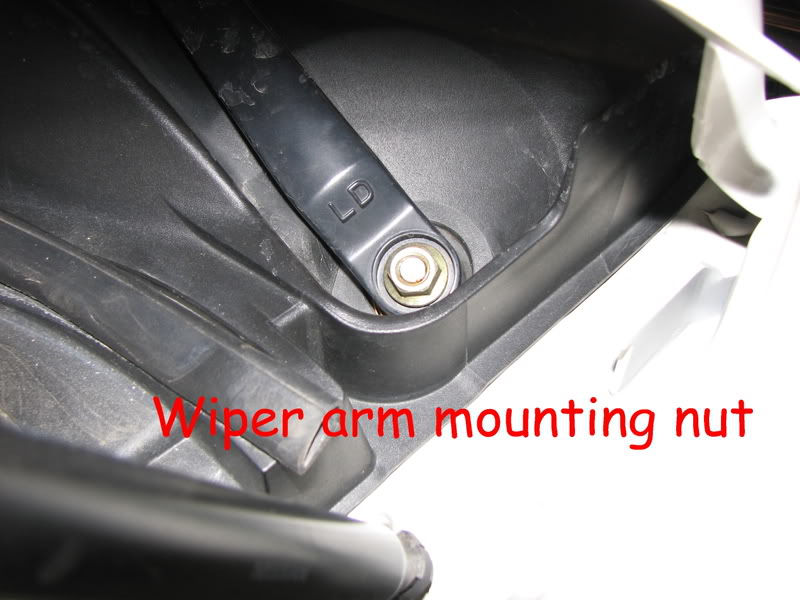
After removing the hood, pull the plastic caps from the wiper arm mounts. Underneath, there will be a nut you need to remove. After removing the nut, the arms will not just slip off. I used a small crowbar to pull up on the wiper arm while I tapped the bolt with a hammer.
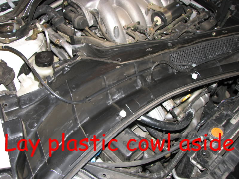
The plastic cowl panel is held in place with 4 plastic fasteners that just push in place. To remove them, I pried up the edge with a screwdriver and used a pair of needlenose pliers to pull them out. Do this carefully or you may break the fasteners off.
Once you get the 4 fasteners out, lift gently on the plastic cowl panel. There are several white clips underneath that will pop out if you lift carefully. After you get it loose, you can lay it on the front of the engine. There is no need to disconnect the windshield washer lines.
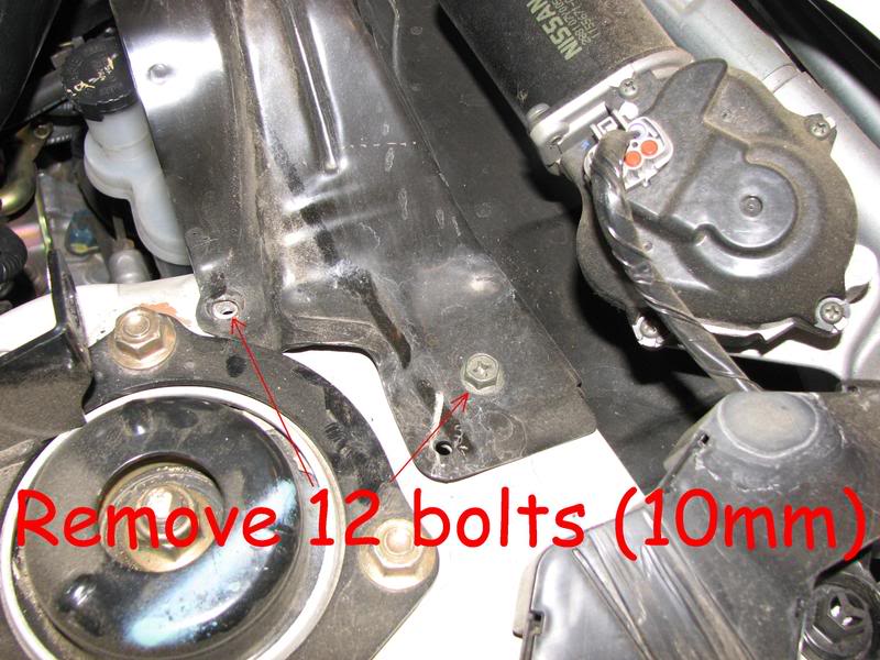
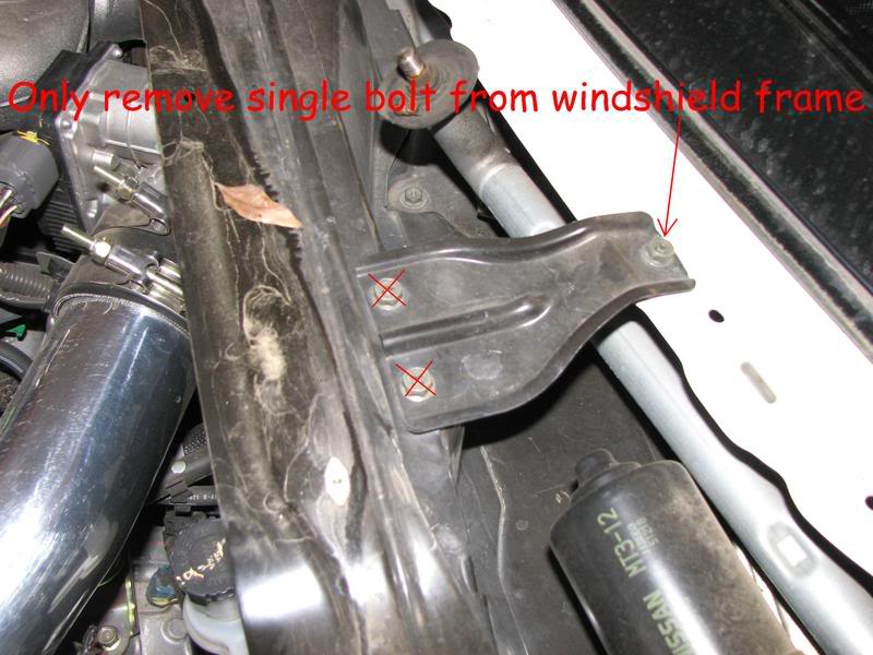
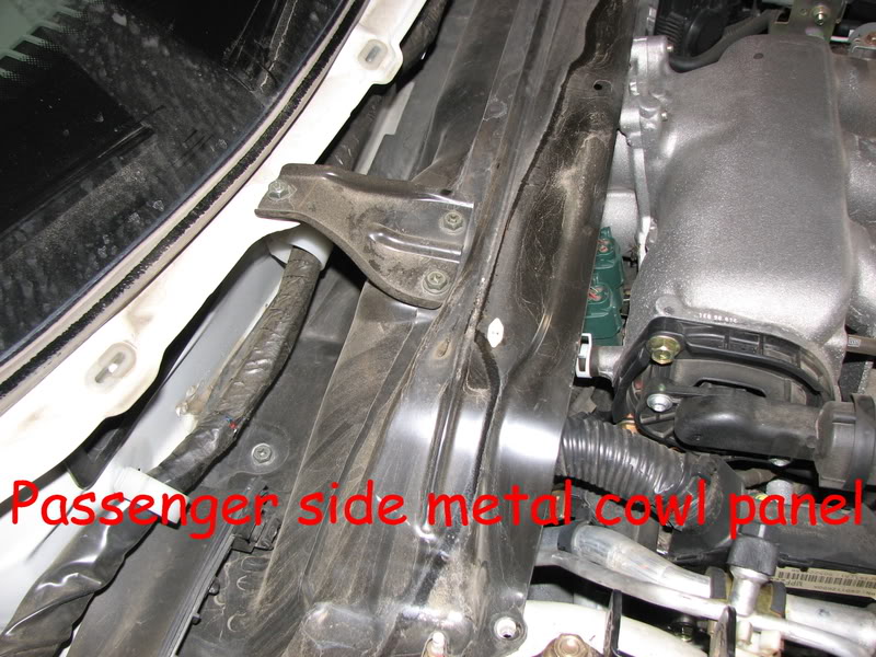
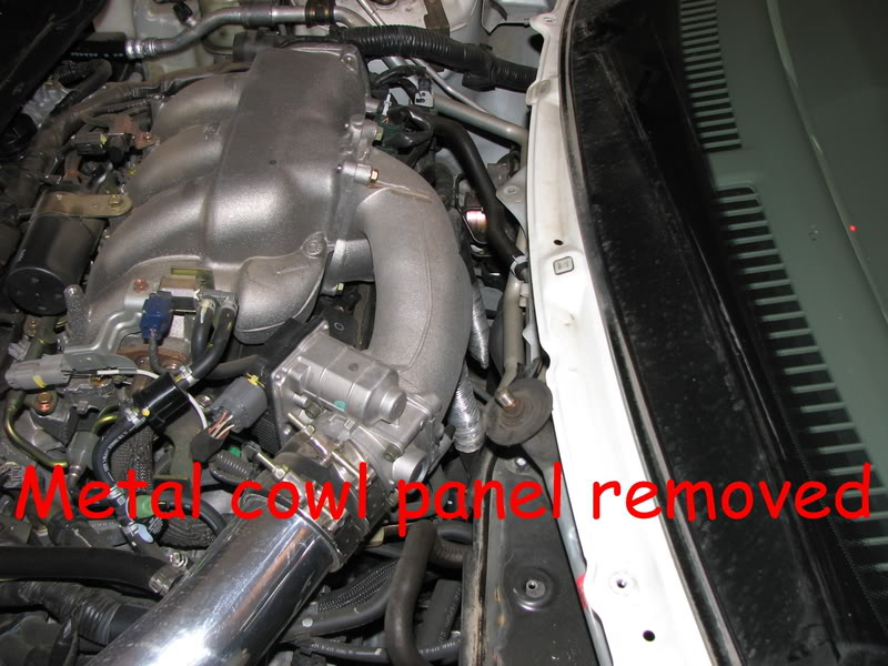
Under the plastic cowl panel there is a metal cowl panel that is held in place by twelve, 10mm bolts. Remove the bolts and lift out the panel.
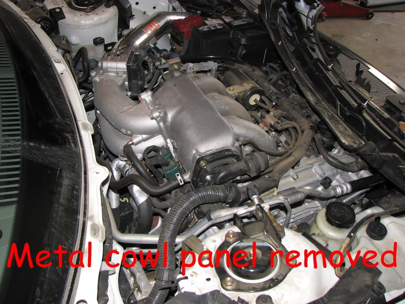
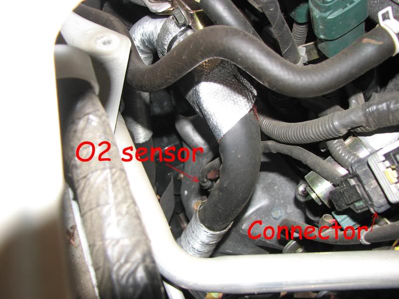
After the metal cowl panel is removed, you will have access to the O2 sensor.
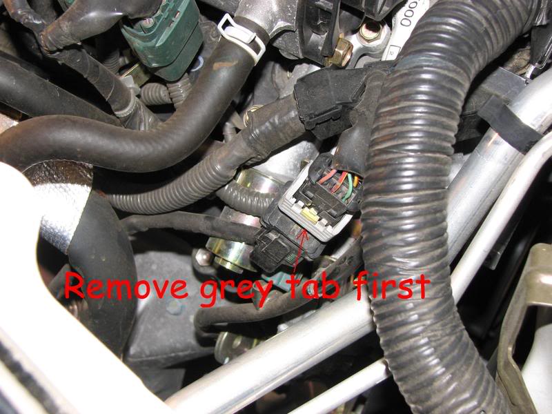
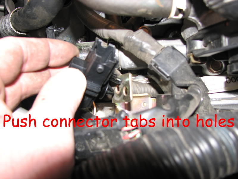
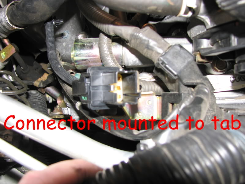
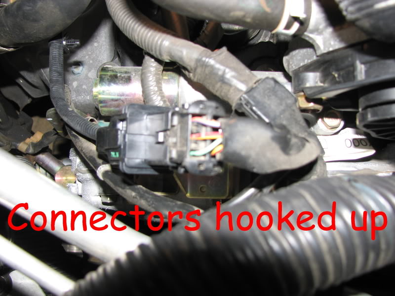
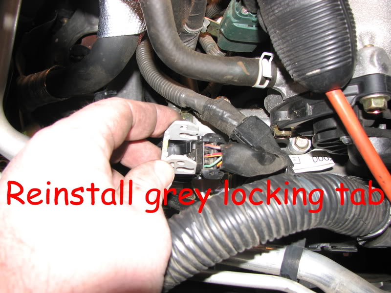
Disconnect the connector first. To do this, you will need to remove the grey locking tab, then pull the connector apart. The portion that is attached to the sensor lead is stuck on a mounting tab.
After you have disconnected the wire, use an O2 socket to remove the sensor from the exhaust manifold.
When you have removed the old sensor, reverse the process for installation.
Important notes:
1. If your new O2 sensor did not come with anti-seize on the threads, put some on. Otherwise, you will never get it out later.
2. DO NOT DROP THE NEW SENSOR! If you do, you will damage it and you will have to replace it.
3. To clear the SES light, disconnect the battery for 20-30 minutes to reset the ECU. Or, you can take it to Autozone or some other parts dealer and they will clear it for you.
4. For all you flamers that want to tell me that my engine compartment is dirty, don’t worry, I detailed it when I was done.
I hope this helps. If nothing else, you can see that you can do this yourself without having to pay the dealer $85.00 per hour to do the job for you.