Category

my6thgen 04-08

Category

Member Credit: MaxJ04

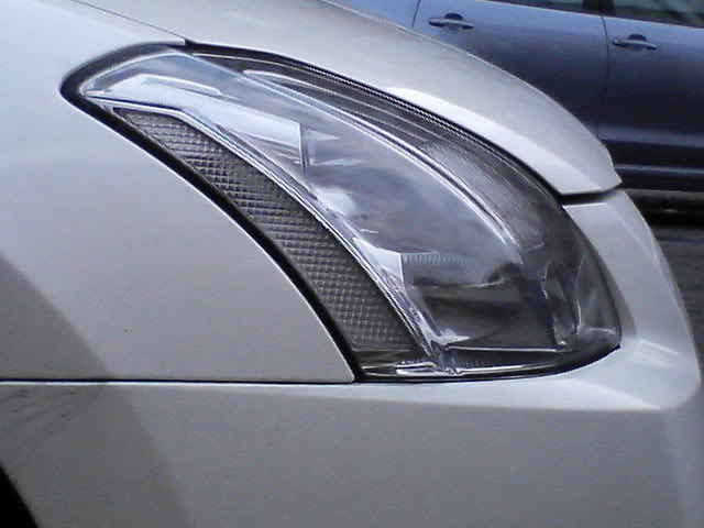
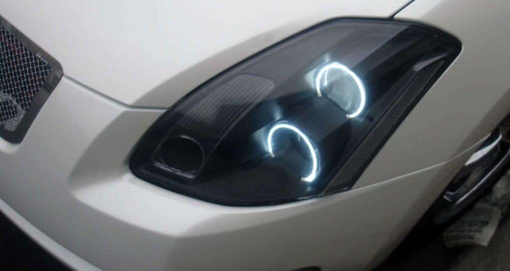
This how-to is for getting rid of the orange side makers on your 6thgen headlights. Headlights look so much better with clear side markers.

Materials needed :

  • OEM Headlight
  • Florescent Light Cover (Home Depot)
  • Silicone
  • Sandpaper 60 Grit to 100 Grit
  • Clamps (2-4)
  • Pliers
  • Chisel
  • Knife or Flathead screwdriver

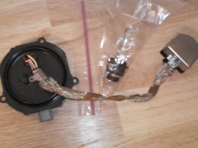
I took the headlights off and I took the HID ballast and the D2S bulbs out of them and place them away from the heat. I didn’t use an oven instead used a heat gun letting me have more control.
Click the image to open in full size.

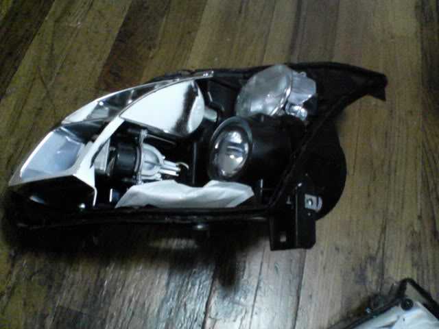
Next when you open the headlight cover there is a screw on the lense take out the black screw and then slowly pull out the chrome piece containing the amber piece. Once done take a knife or a screw driver ( flat head ) and slowly pry out the amber piece the lower part is easier to take out but you have to jiggle out the upper part because is tight.
Click the image to open in full size.Click the image to open in full size.

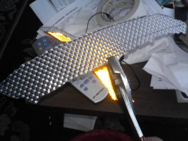
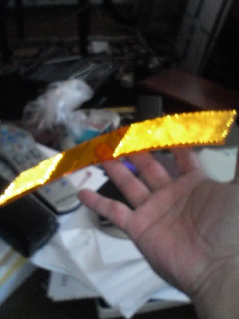
Take the florescent light cover * under 10 $ from home depot* and using the chisel cut a piece that can be used to trace out the amber piece in which you would replace. Use the chisel to cut the piece of florescent light cover to a smaller size or use a pair of pliers to clamp out the unnecessary pieces that are remaining and close to your out line.
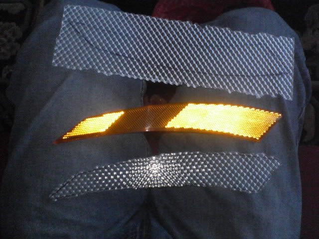
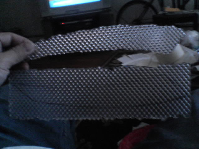
Click the image to open in full size.Click the image to open in full size.Click the image to open in full size.

Getting near the outline that you traced? Then is time to start sanding I used 60 grit and then worked with 80 to 120 .. but mostly 60 and here are the end results but close enough keep sanding until is small enough to fit back into the lenses.
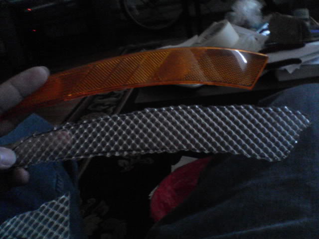
Click the image to open in full size.

Use silicone to glue it on the edges of the chrome piece all you need is to use the tip or something to align it to the edge so that it won’t show the glue . next use clamps to hold it in place and leave it there until it dries. After its dried put back the chrome piece into the lenses and screw it in heat up the oven or use the heat gun to put it back together and then just repeat to the other side.
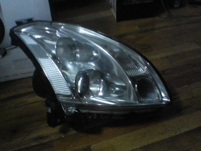
Click the image to open in full size.

Put back your D2S bulbs and ballasts all these came off fine for me just with patience and screwdrivers.. All is done take a walk outside and put it back into the car and put it all together and get some stealth bulbs .. I used Sylvanias 1157’s that are clear when off but orange when lit.

Finished Pics
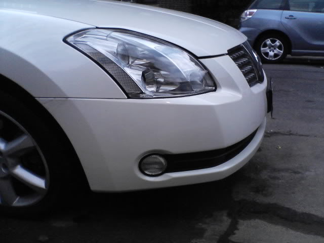
Click the image to open in full size.Click the image to open in full size.

Loading

Member Credit: EddyMaxx

I was getting the following code: P0335 Crankshaft Position Sensor A Circuit Malfunction 

This code was causing my car to go into “limp mode” and wouldn’t go over 3500 RPM. Also, don’t confuse this sensor with the Camshaft Position Sensor. The sensor is very easy to change. All you need is a 10MM socket.

Symptoms:

  • Car hesitates to start (or may not start at all)
  • Engine stalls when it is warmed up
  • CEL Code: P0335 Crankshaft Position Sensor

The Fix:

I ordered a sensor from eBay which claimed to be OEM. The part number is 23731-AL60C. While the car started up fine, it still wouldn’t rev over 3500 RPM. Likely a faulty sensor. So I went to my local Advanced Auto and purchased a new one. With the discount code, it came out to $35.00.  After installing the sensor the car started up perfectly and went out of limp mode. I went for a quick drive and code was permanently gone. I’m always about OEM products when it comes to sensors. However, in the case the aftermarket one below work just fine and comes with warranty. Just ensure you keep the receipt.

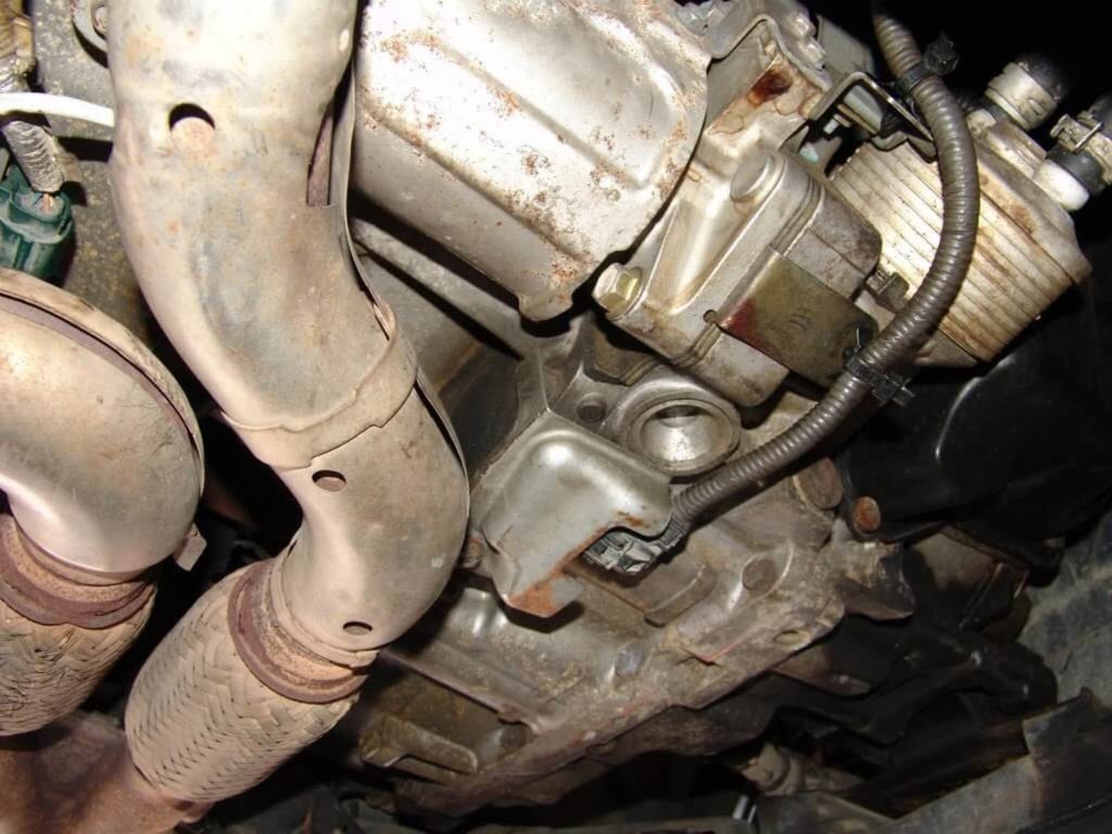
5-Speed Auto Crankshaft Position Sensor Location

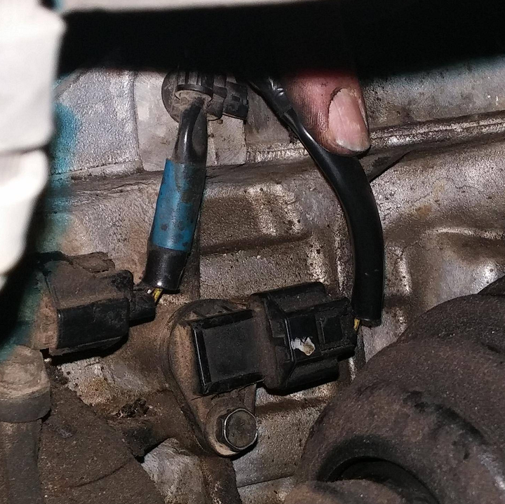
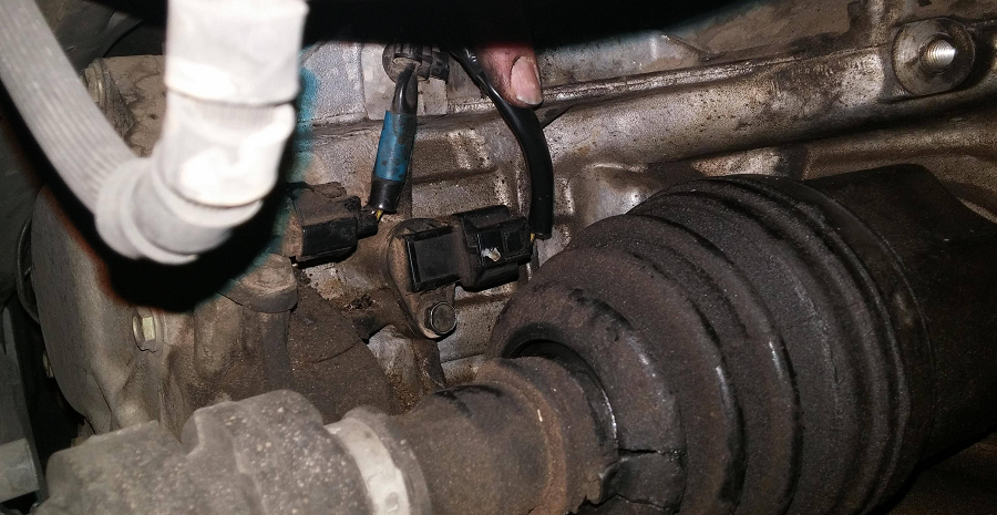
The crank sensor is located at the bottom center of the engine just below the flywheel area.

Photo Credit: Sparky Answers

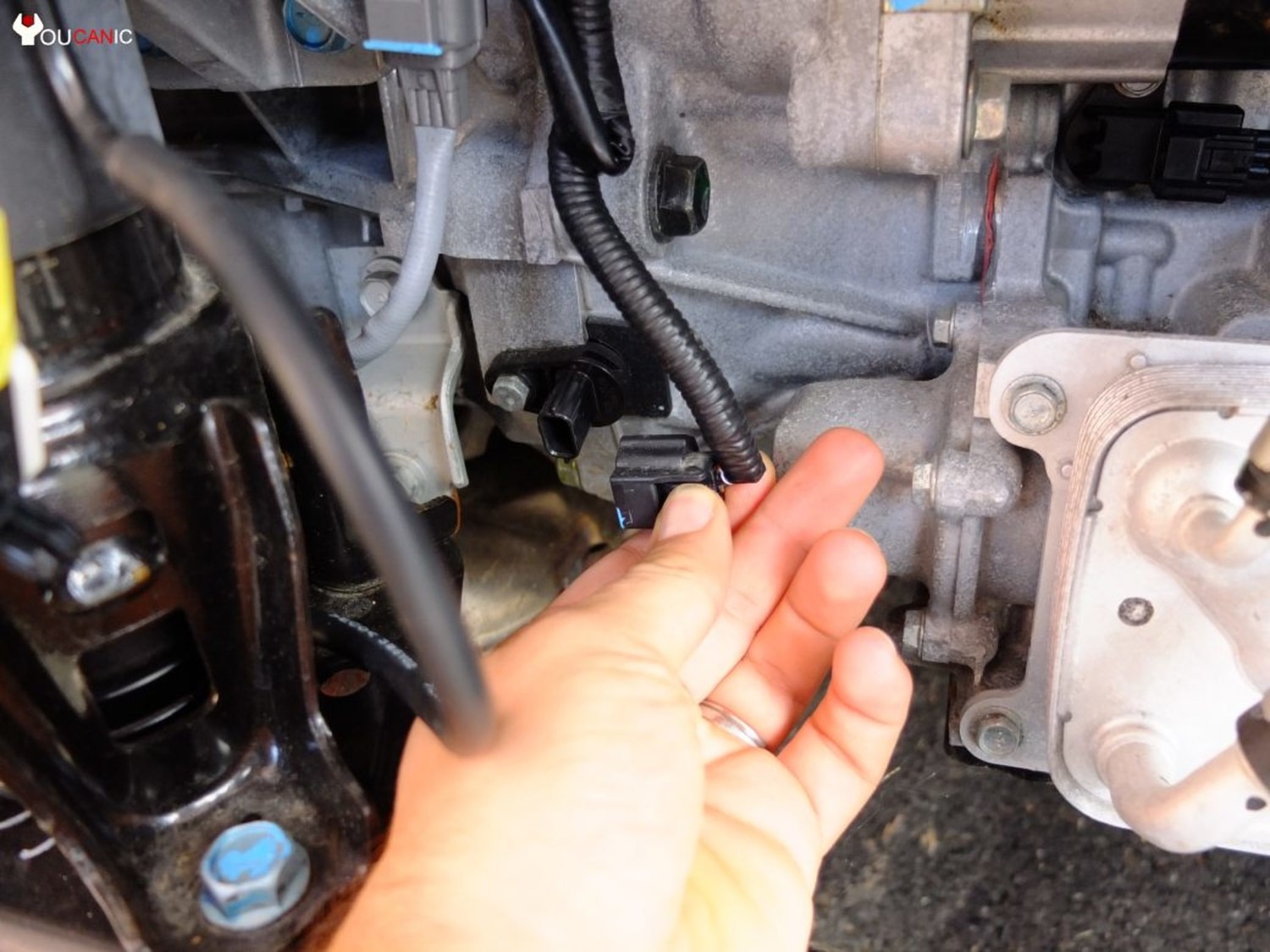
4-Speed Auto Crankshaft Position Sensor Location

Photo Credit: Youcanic


Loading

Member Credit: EddyMaxx

I was getting the following codes together, P0720 and P1574 on my 2004 Nissan Maxima which has a 4-Speed Automatic Transmission.

My Symptoms:

  • RPM gauges would stop working intermittently
  • Speedometer would flicker from time to time
  • My cruise control lights were flashing (when pressing cruise control)

Code Definitions:

  • P0720: Output Speed Sensor Circuit Malfunction aka Vehicle Speed Sensor
  • P1574: ASCD Vehicle Speed Sensor

The Fix

I was getting ready to just buy and replace the sensors. However, I decided to check the harnesses for these two sensors. Surely enough, the harness had an exposed wires due to corrosion and the connectors were very loose. I fixed the exposed connections and tapped up them up nice. I also ensured the harness plugs were properly secured. And PROBLEM resolved for these two codes.

Below is a photo of the two sensors.

Photo Credit: Picodroid

Loading

Member Credit: Whore-Jay

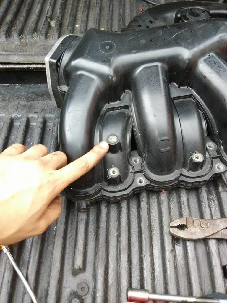
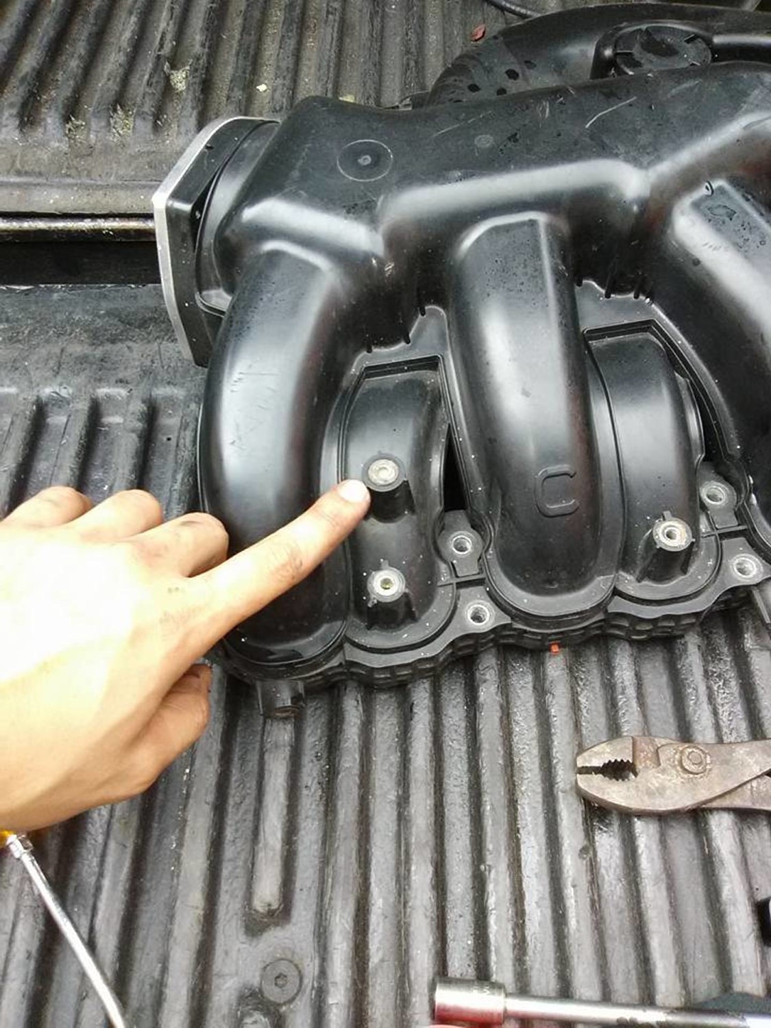
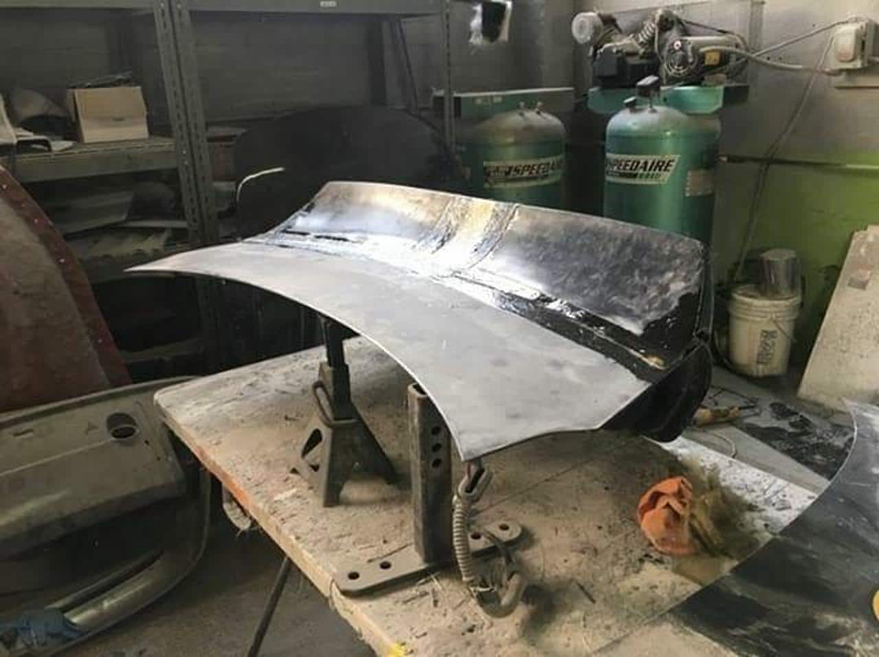
The SSIM (Secret Sauce Intake Manifold) was created years ago by member SR20DEN. This involves cutting the shelf out of the main chamber of the upper intake manifold and removing the VIAS assembly. This will still lose a little low end power, but the gains in the top end are very noticeable. It’s definitely a modification that is worthwhile.

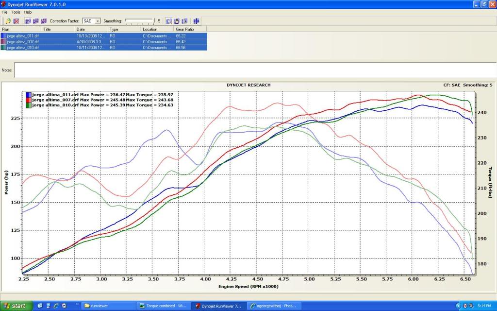
Below are the results of 3 different Intake Manifold setups. All runs done on the same dyno with the same AFR (tuned for 13) and around the same temp. Stock (runfile11), SSIM (runfile10), VIAS delete (runfile7). Your constructive input is welcome but I am not here to argue about any of my results, this is what I did and that is what I got end of story so please no flaming. Enjoy!!!

Stock IM with functional VIAS.

Stock IM with VIAS deleted, NWP Block plate used.

SSIM with VIAS deleted, NWP Block plate used.

All three HP overlay.

All three TQ overlay.

All data combined.

My thoughts on the SSIM vs Stock.

  • First of all I am suprised that the SSIM did so poorly when compared to both the Stock setup and the VIAS delete.
  • It posted losses across the board, it only begun to edge out the stock setup after 5600rpm with a gain of 12hp
  • at 6300rpm.
  • Against the VIAS delete setup it made the same peak power but posted some gains after 6100rpm, average of 5hp with a peak of 7hp at 6500.
  • It was totally killed by the Stock setup from 2500rpm until 3800rpm, max of 24tq at 3400rpm. Never made any gains in usable torque.
  • Killed by the Stock setup for HP as well, losses from 2500rpm until 3900rpm, an average of 10hp with a peak of 16hp at 3500rpm lost to the stock setup.
  • From 3900 until 5600 they were about the same.

My thoughts on the VIAS delete vs Stock.

  • 3800rpm seems to be the magic number in this comparison. Below 3800 the Stock setup is better but after that its all gains with the NWP Blockplate and the VIAS delete!!!
  • From 3800 all the way to redline with the VIAS delete I showed an average 8hp gain across the board with a peak of 10.5hp at 6000.
  • From 2700 until 3800 the Stock setup was good for an average of 8hp over the VIAS delete with a peak of 9hp at 3400.
  • From 3800 until redline the VIAS delete made an average of 8tq more with a peak of 10.5tq at 4200.
  • From 2800 until 3800 the Stock setup was good for an average of 10tq more with a peak of 16tq more at 3400.

The verdict….. Its really just up to what you want to drive with, I am choosing the NWP Block plate with an unmodifed IM for now. 

  • I like the power from 3800rpm until redline rather than power below 3800rpm, I feel the losses down that low are worth the gains I see up high. When I stomp on the gas I dont stay below 3800 for very long, this makes the VIAS delete a beneficial mod IMHO.
  • The gains from the SSIM is irrelevant since it only starts to make HP after 6100rpm and totally destroyed all low end torque. Since I run out of engine the SSIM may be a viable option with a TS ECU and a higher redline, timing etc, etc.

*Mods*

  • Unorthodox racing UDP
  • SSAC headers (no cat)
  • 2.5″ Catback
  • Magnaflow 27X6″ resonator
  • Stillen Exhaust
  • Frankencar WAI
  • Tuned APEXI NEO

Loading

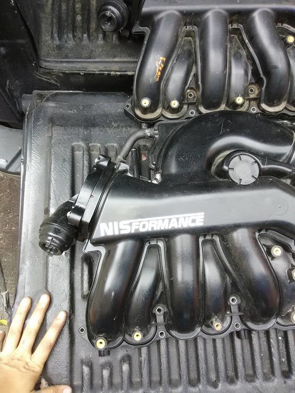
This is a gallery of Secret Sauce Intake Manifold (SSIM) Setups. The SSIM (Secret Sauce Intake Manifold) was created years ago by member SR20DEN. This involves cutting the shelf out of the main chamber of the upper intake manifold and removing the VIAS assembly. This will still lose a little low end power, but the gains in the top end are very noticeable. It’s definitely a modification that is worthwhile.


Loading