Year: 2005 Model: Maxima Color: Custom Lexus IS-F White Transmission: Manual 6-Speed Trim: SE
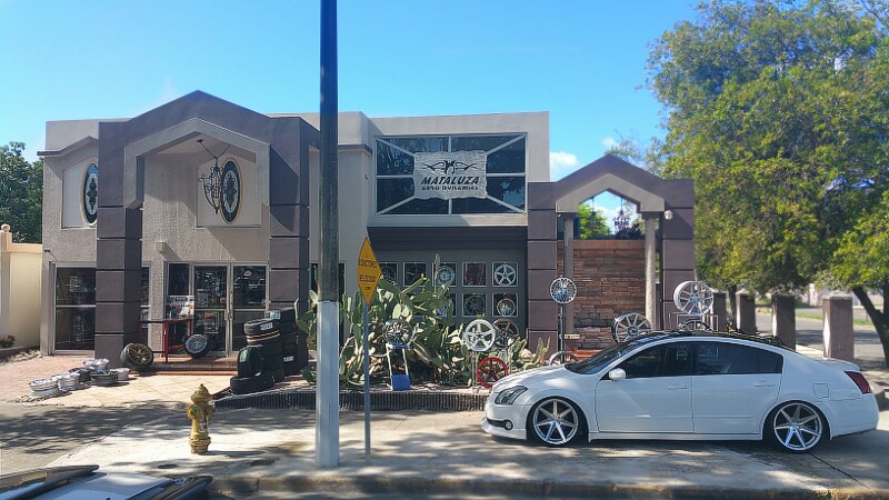
This is Richard’s 2004 Nissan Maxima. He lives in Ponce, Puerto Rico. His 6thgen has come a long way and continues to look better and better! More progress and updates to come. Awesome work.
This 2007 Nissan Maxima came in with the complaint that the gas gauge was stuck on empty. Actually a closer look revealed that the gauge needle was stuck under the empty stop peg. Due to the coloring of the instrument cluster lens I was unable to get a picture of this before disassembly.
If you have a strong magnet you can use it to move the gas gauge needle into the correct position. If you do not have strong magnet or if you just need to know how to remove the instrument cluster, continue reading.
The top cover over the instrument cluster assembly is held in place by spring clips as shown in the next picture. To unfasten the cover lift up to release the clips. Note that there is a tether cable that attaches the cover to the dash carrier. It does not need to be removed. In fact I do not even know if it can be without damaging something.
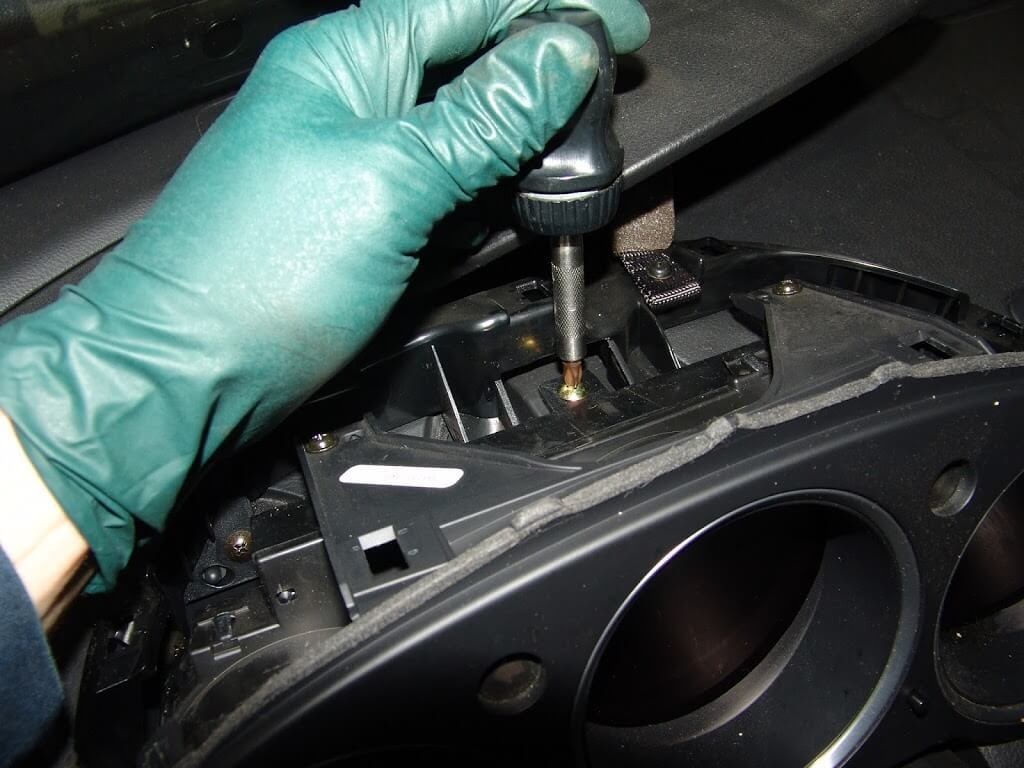
There is one phillips headed screw behind the middle of the assembly that needs to be removed.
I was also hoping that the other two phillips screws were all that was left to remove the instrument cluster. They do have to come out for the final disassembly to correct the needle issue but not now.
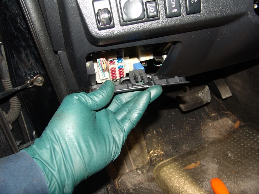
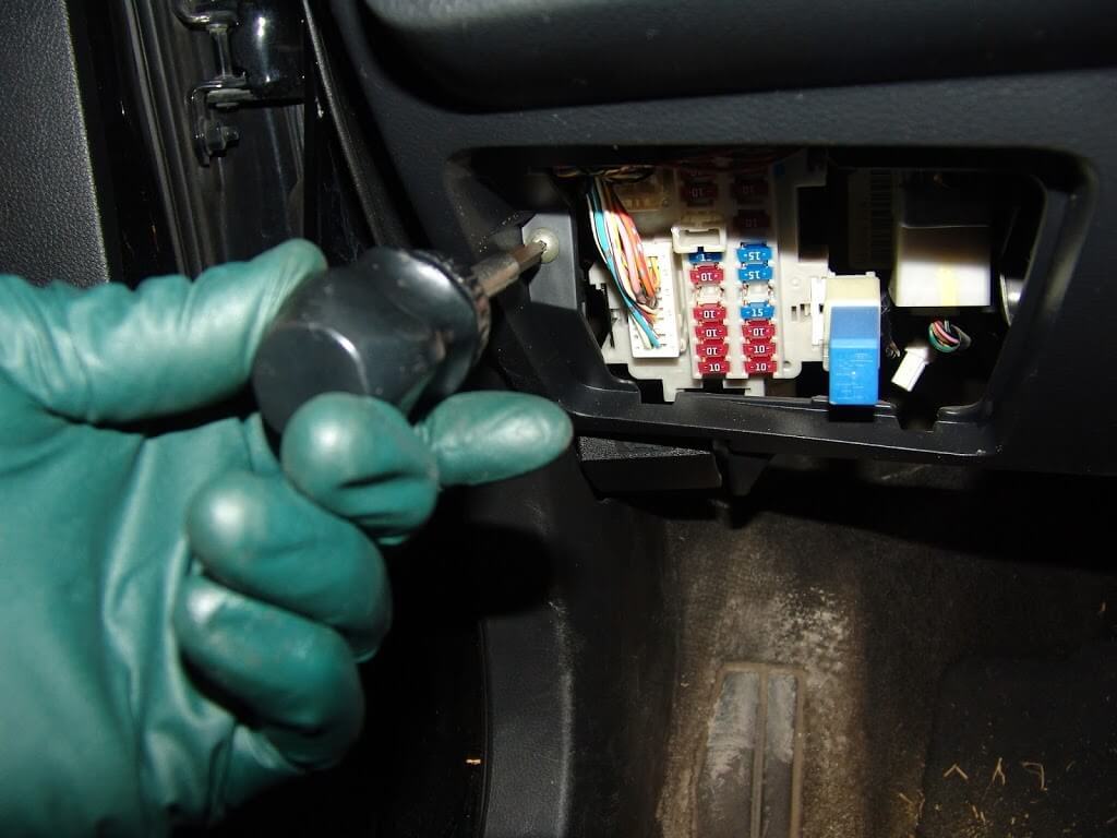
I could feel something holding the bottom of the instrument cluster so I wanted to remove the covers under the steering column. Removing the fuse box cover reveals ons crew to the left.
It has a torx head. There is also one other matching screw under the right side of the panel.
I am not sure if the inner steel panel actually has to be removed but it is only two screws and it made it much easier to take some of the following pictures.
To remove the two lower retaining screws I used a long phillips head screwdriver and magnetised the tip. Also I extended the steering column all of the way out towards the driver’s seat and then fully down.
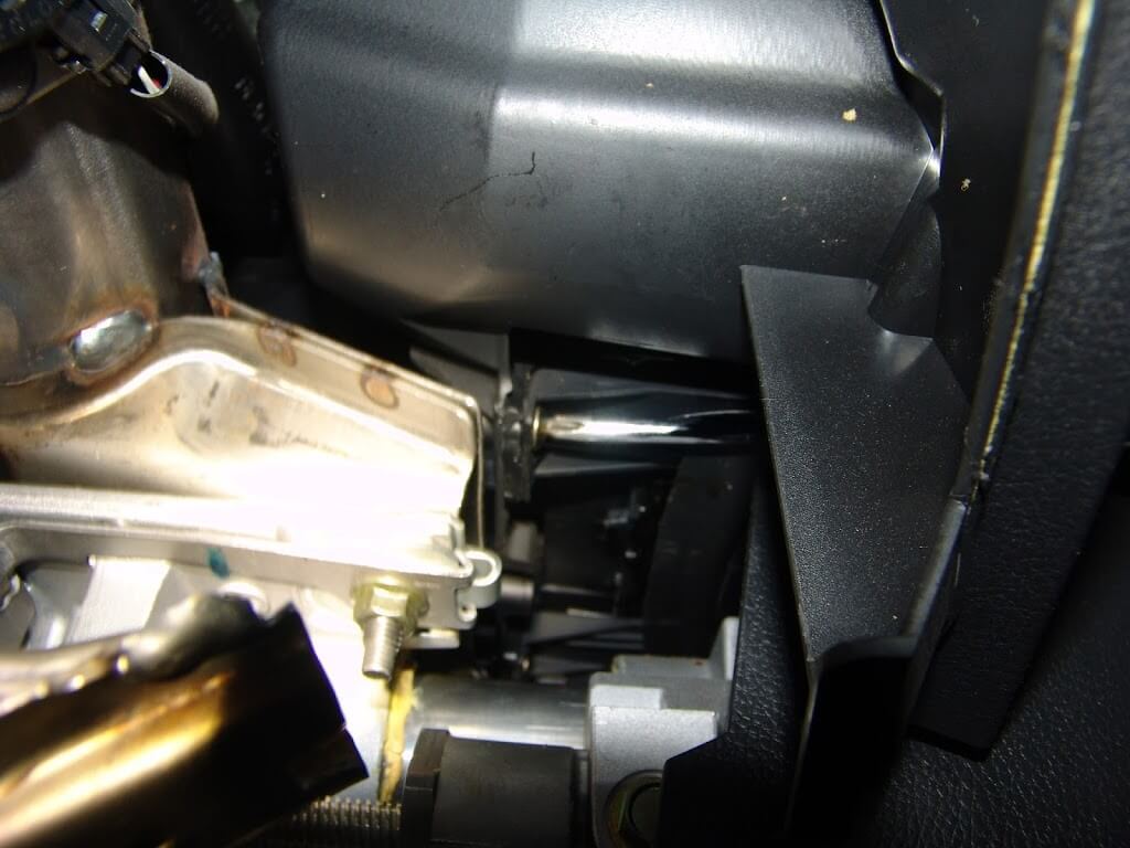
Looking under the dash I could see where to move the tip of the screwdriver to align it with the screw.
The one on the right is a little bit more difficult to locate and remove. In fact I had to get my longest phillips screwdriver out to do this efficiently. For reassembly I inserted the screwdriver on the left side of the column and attached the screw to the magnetic tip, then carefully slid it to the right to align it with the mounting hole. I know this takes a few special tools and is somewhat tedious but it beats having to drop the steering column and possibly more.
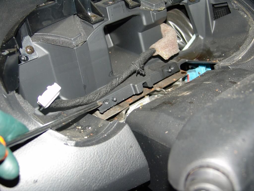
There is one harness connector to remove. The harness also is attached to the cluster by clip shown in the center of the next picture. I am pointing to the left lower mounting screw hole with my screwdriver.
There are a series of plastic clips all of the way around the instrument cluster assembly that have to be dislodged. Also the two screws mentioned earlier.
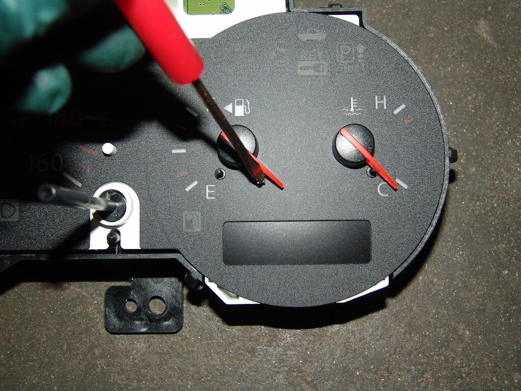
With the cover removed it is easy to see that the needle is on the wrong side of the stop peg.
A simple little flip with my screwdriver…
…and the needle is back in it’s correct location.
If you want to avoid this problem altogether, never disconnect and reconnect the battery connections with the ignition switched on.
This document has been composed with the online instant web content editor which can be found at htmleditor.tools
This 2006 Nissan Maxima came in with the complaint that the gauges and the a/c controls did not work. After the obvious fuse checks I went to the most common location for this problem in Nissan Maximas.
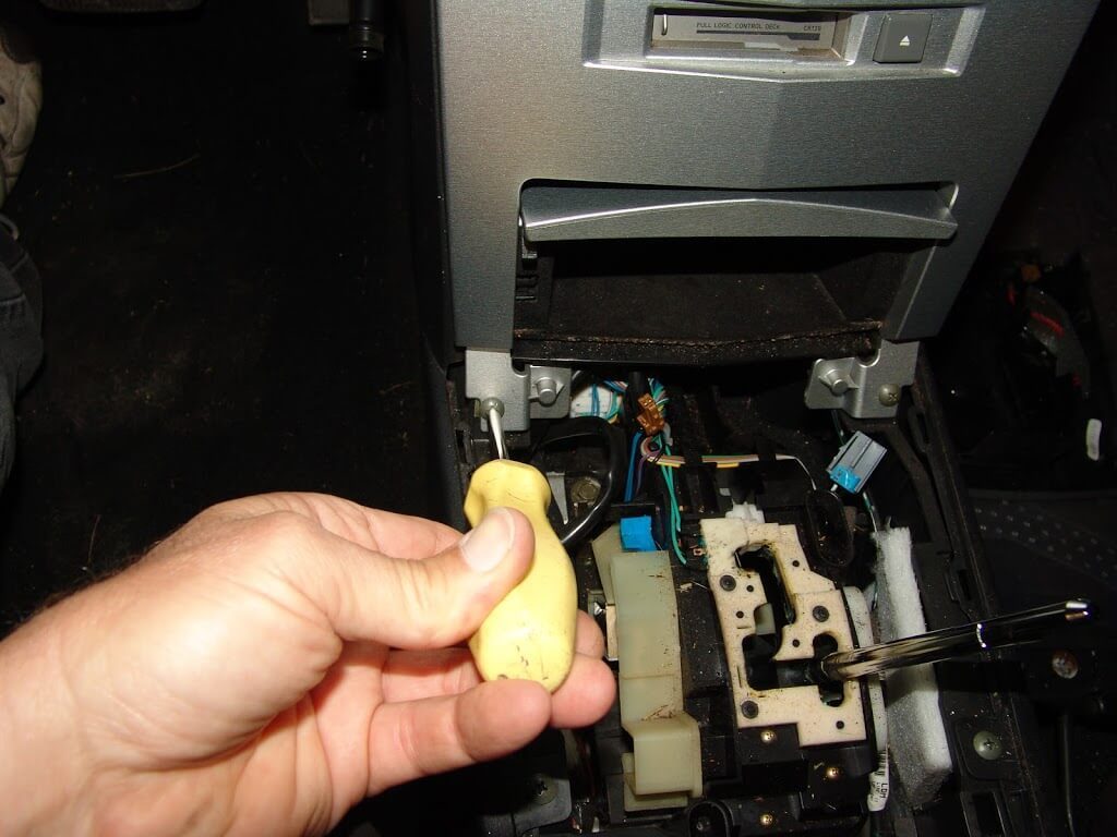
The problem is located behind the a/c control panel and repairs start with removing the shifter knob or handle assembly. To do this the bottom trim piece needs to be pulled straight down. Some wiggling is needed.
Once the trim piece is lowered the retaining clip will be exposed. Use a screwdriver or a pair of pliers to pull the clip out. Be careful not to lose it.
In the following picture you can see all three parts of the handle. The knob at the far right. The lower trim tube in the center and the retaining clip to the left.
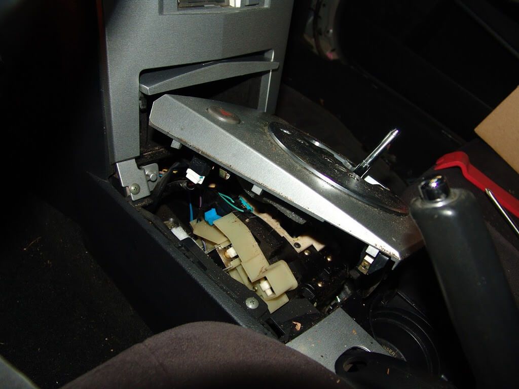
To remove the shifter’s trim panel it can be lifted at the rear of the panel as shown below.
After the trim plate is lifted you will find that there are wires attached to the front edge.
I found it easier to disconnect the wiring on the passenger side of the panel first. Then it can be rolled to the left to disconnect the remaining wires. There are thumb latches or locks that have to be depressed before the harness connector can be removed.
Now that the shifter’s trim panel is out of the way the two lower attaching screws for the a/c controls and the cover over the cassette player are exposed and easily removed.
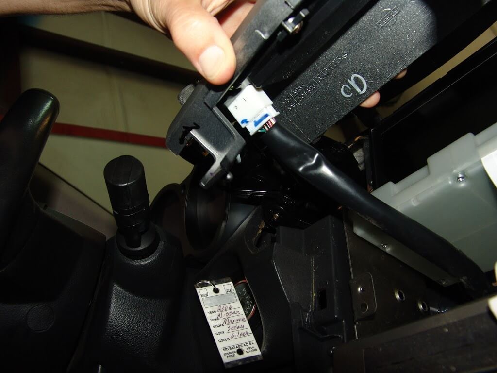
The lower edge can then be pulled out and then the top can be worked free. There is a ribbon cable connector that has to be taken loose. Care should be taken as it is easily broken.
There are two more screws at the lower edge of the radio control panel. Once removed it too can be pulled loose from the dash.
There are wires attached to the backside of the panel.
Now that all of the panels are removed you can finally see the unified meter and a/c amplifier module assembly. The white box in the middle of the next picture with the ribbon cable attached.
I took a quick look at the underside of the module and saw this. Those do not look like factory holes in the plastic.
I finished removing the attaching screws for the center stack assembly.
After pulling it loose from the dash I could access the screws on the side panels. I removed the two upper screws that hold the display face in place. The screws only need to be removed from one side of the assembly.
There are two screws that I had to take out that attach the module to the frame. One on either side and the rear of the assembly.
The screws are different so I was sure not to mix them up. The screws that held the display are shorter and have machine threads. The ones that attach to the plastic module are longer and have much coarser threads.
Note the slot in the module case resembles that of a piggy bank. When shaken it rattles like there is something loose inside.
I went ahead and removed the five phillips headed screws that hold the module together.
I lifted and removed the one cover.
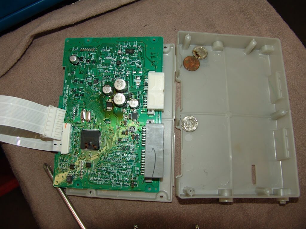
Then I lifted the circuit board and found 21 cents inside the cover.
There were multiple burn marks on the circuit board.
There were also burnt spots on the coins.
The new module is supplied with a piece of felt tape covering the slot. The old module had the part number 27760 7Y01A printed on the outside cover. The new part had the part number 27760-7Y01B on the box.
In a previous life the horizontal panel below the display was used as a shelf. At least for coins.
The new module installed and everything back to normal.
The motto of this repair would be “read the owners manual and only use recommended spaces for storage”. Another adage would be “When does $0.10 plus $0.10 plus $0.01 equal $400+? When you use the unified meter and a/c amplifier module as a piggy bank.”
This 2004 Nissan Maxima came in with the complaint that the transmission would not shift properly. The customer stated it felt like the transmission was starting in a high gear. I really did not want to work on this vehicle as the customer informed me that the engine and transmission had both been replaced with used parts. You just never know what you will run into when going behind someone else. First the code checks.
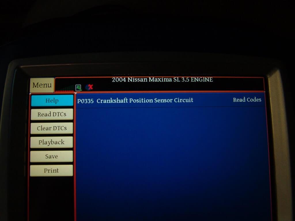
Code P0335 stored in the PCM. although the customer had not complained about it, I had noticed that there was an extended crank time before the engine started.
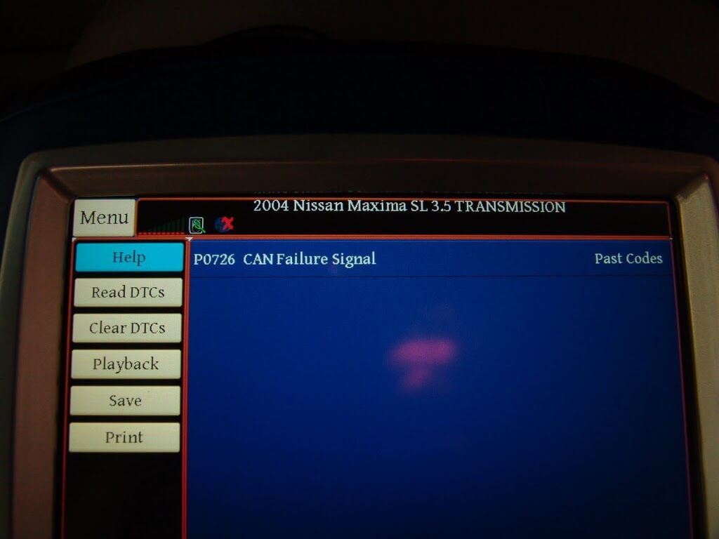
The TCM had a code P0726 stored for a CAN Failure system. In case you were wondering CAN stands for Controller Area Network. This means that there is a communication problem between modules.
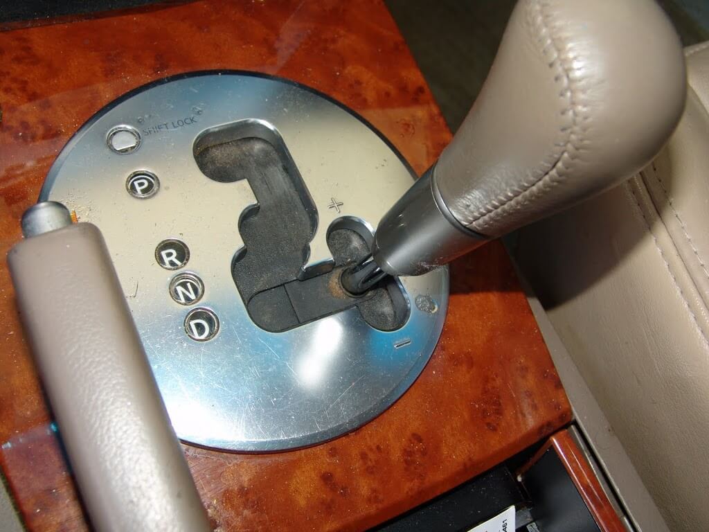
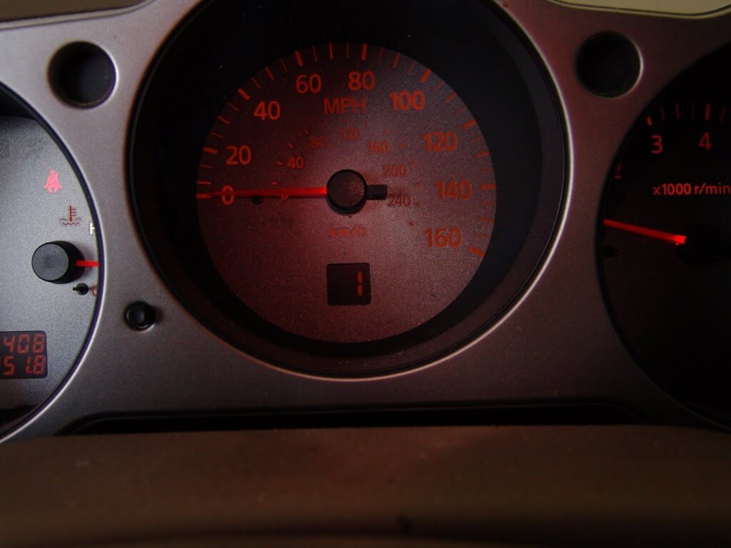
With the key on and the gear selector in the manual shift position the gear indicator in the instrument cluster shows that the transmission is in the 5th gear.
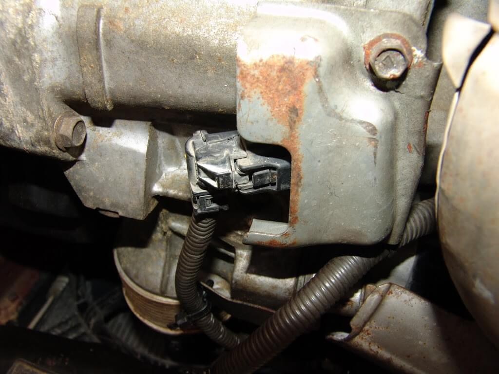
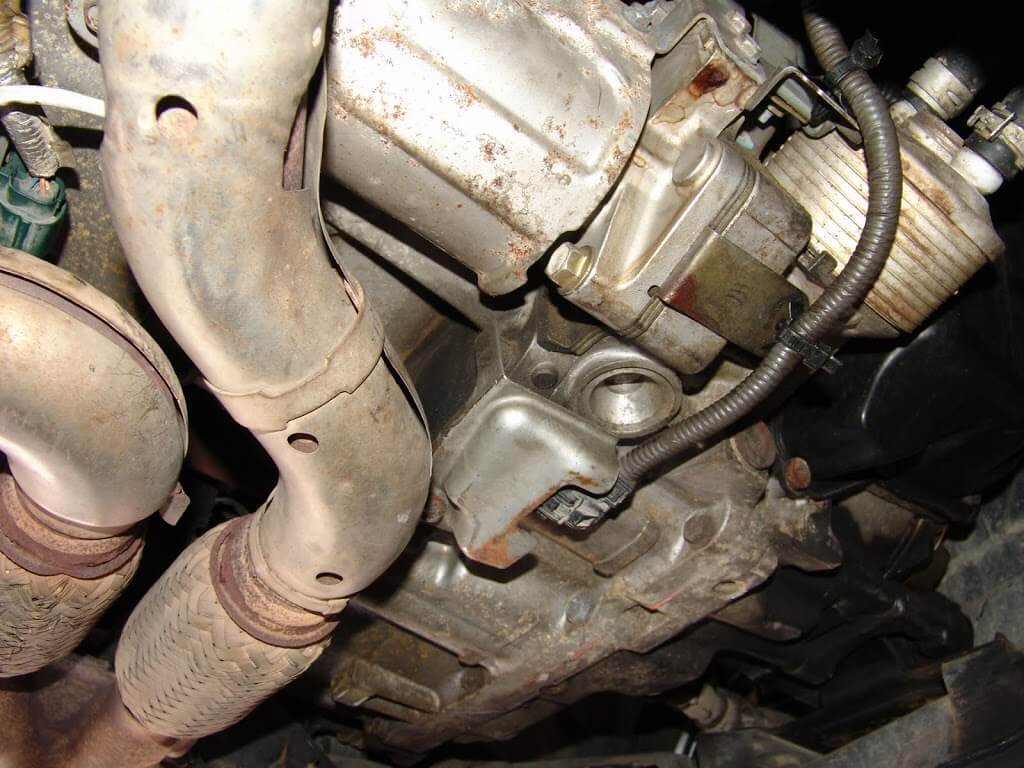
I wanted to do a little research, in that I have never seen a code P0726 before and I wanted to know a little bit more about it. I found that there are some real world anomalies with the factory diagnostic procedures. The TCM is supposed to use a crank sensor signal along with other data to determine shift patterns. The real world has found that cam sensor signals are also involved with this process. The engineers it seems did not plan on this or they did not inform the service information writers about it. Since I did have a crank sensor code I decided to start there. The crank sensor is located at the bottom center of the engine just below the flywheel area.
Everything looks okay here or does it? Kind of strange how the end of the connector looks like it is lined up perfectly with the edge of the sheet metal shield. A gentle pull revealed that it was not fully seated.
Could it be that it was that simple. This vehicle had been to two other shops before arriving at mine. Using a pry bar, I straightened out the sheet metal shield.
Then installed the connector until the lock snapped into place.
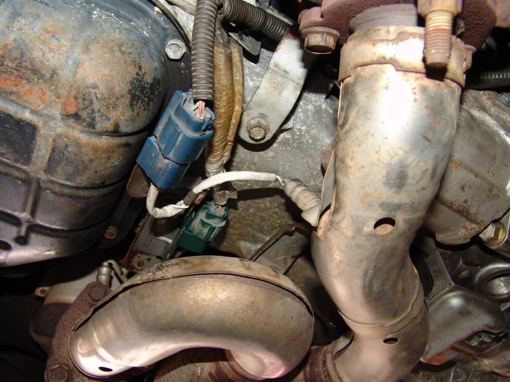
Of course while I was looking around at the problem I noticed quite a few things out of position.
Gee, you think a wiring harness laying on an exhaust pipe might cause some problems?
It amazes and worries me that someone can actually get an engine and or transmission in and out of a vehicle and leave something like this a mess. I had to round up a few bolts and finish installing a couple for brackets and heat shields. Then reroute the oxygen sensor wiring so that it would not be laying on the exhaust.
It does not look too bad now but I informed the customer that the engine installation needs to be gone over to make sure nothing else is loose or not installed.
Now the shift indicator shows that the transmission is in 1st gear. Both the PCM and TCM codes are now gone. The engine also starts as it should.
This one will be back in a few weeks to finish going over the wiring under the hood.
Learn the solution of the Rubiks Cube and measure your solution times with the online timer.
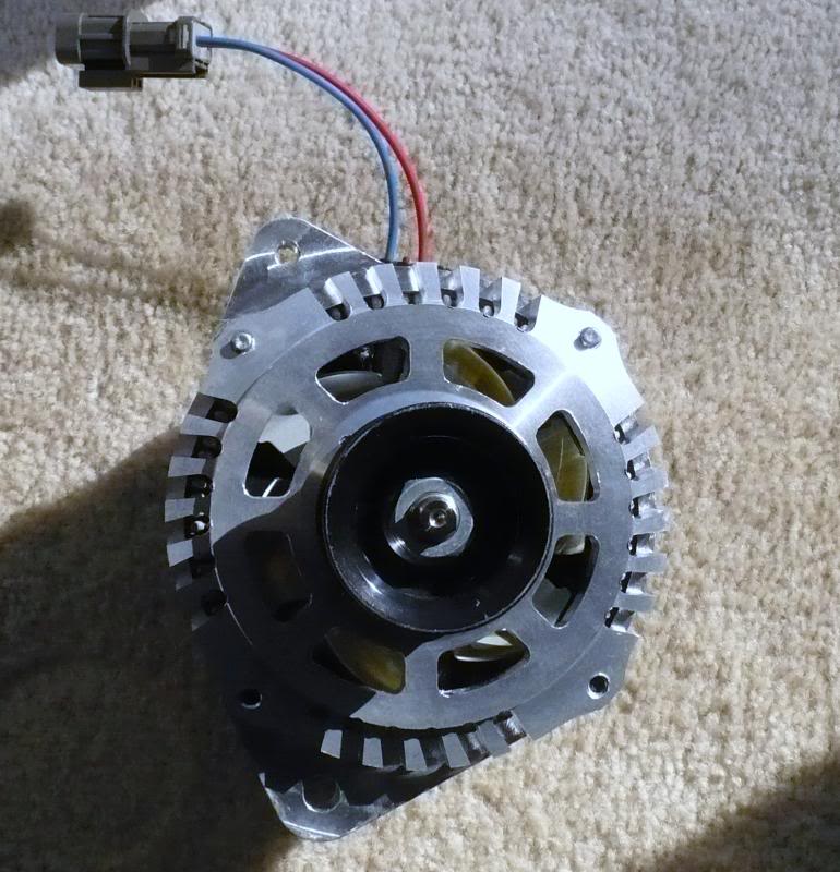
In the process of installing my supercharger (which runs of alternator), I decided to upgrade my OEM alternator to a DC Power 270 Amp Alternator. The OEM alternator is 110 amps. I paid $300 bucks for the DC 270 Amp Alternator. They usually go for $600+ according to the DC Power website.
The DC Power alternator was a direct fit to my 2004 6thgen Maxima. The installation was also straight-forward. I also did the “BIG 3” and upgraded all the wires to 1/0 gauge. This included the grounds and charge wire. I upgraded my battery to a Northstar AGM31 as well (but will save that for another post).
Please keep in mind the factory cables weren’t designed to handle the power of a higher-output alternator, and can restrict the flow of electricity (or cause cables to fry up). The “BIG 3” upgraded is highly recommended.
Fitment:
2002 -2006 Nissan Altima 3.5L V6 VQ35DE
2004 -2008 Nissan Maxima 3.5L V6 VQ35DE
Installation Photos:
OEM Alternator
DC Power Alternator vs OEM Alternator
Perfect Fitment
Additional Reference Photos:
Alternator Specs
Mounting Type
Direct fit to OEM Mounting
Output Voltage
14.8
Idle Amperage
200
Hot Idle Amperage @ 200ºF
180
Max Amperage
270
Hot Max Amperage @ 200ºF
250
Pulley
6 Groove Hard Anodized 6061 Billet Aluminum
Doesn’t affect vehicles PCM, Check Engine Light or Charge Light
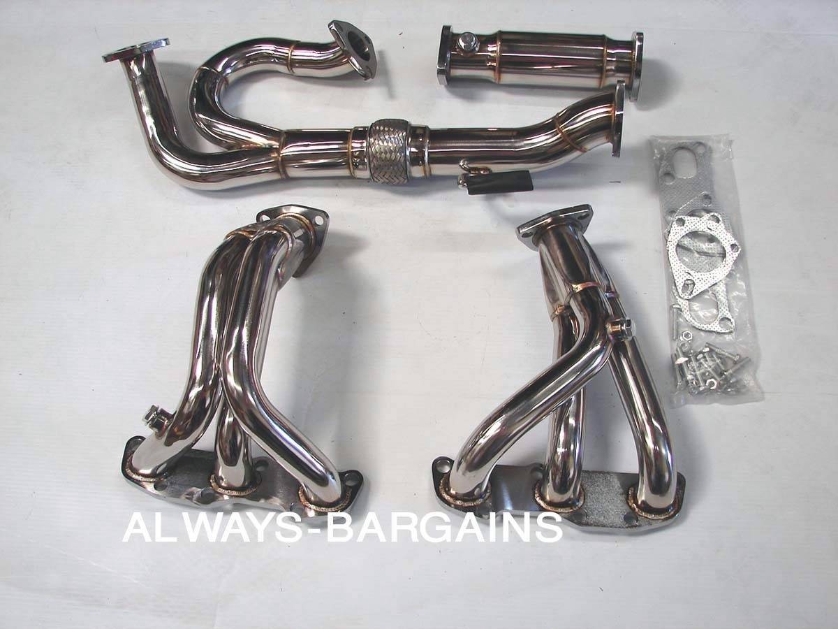
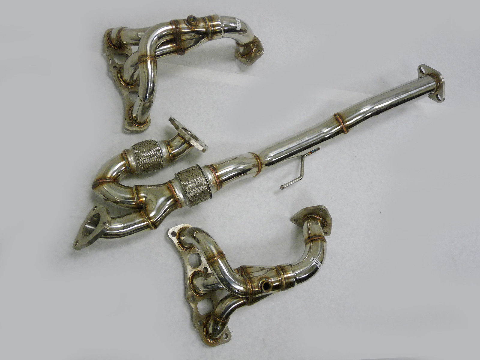
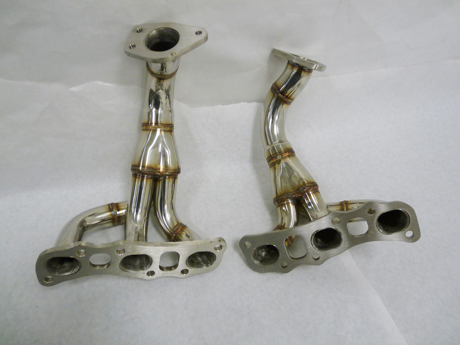
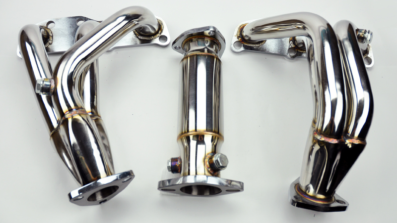
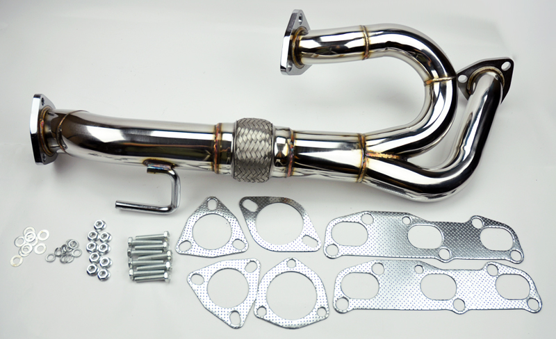
When Maxima owners get the infamous P0420 check engine light code for bad pre-cats, the best route is to go with eBay headers. However, when you search eBay there are various types of header listings that pop-up. This post goes into a little more details about what modification are required on the different types of available eBay headers.
The headers on eBay are listed as VQ35DE Altima 3.5 headers. They will work fine on all 2004-2008 6thgen Maxima’s.
So which headers should I buy for my Maxima? We would recommend going with the Manzo headers for either 6-Speed or Automatics.
General Information:
Inlet: 2″
Outlet: 2.5″
Made of High Quality T-304 Stainless Steel Material
Mandrel Bent Tubing & CNC Machined Flanges
Modification For Automatic:
You will need to shave down the flange on the header. You do not need to shave the starter as some have done but also an option. We recommend the flange itself.
The y-pipe for these Manzo headers do sit low, so many members modify it to lift it up a bit.
Weld bungs for secondary O2 Sensors. There are two sensors. You also need to extend the harness.
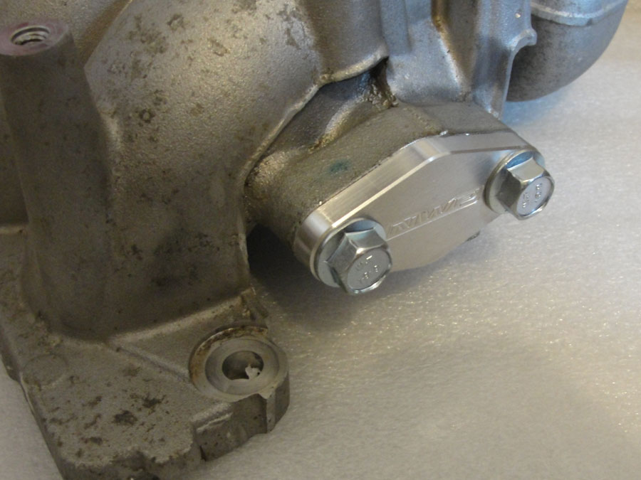
Weld in EGR Bung on Rear Header
If you are tuning with UpRev, then you can block off your EGR with a plate and have it tuned. You can get the EGR block-off plate from NWP Engineering for $35.00.
When properly tuned it will not throw a code. You can also add a resistor in the EGR temp sensor.
Modification For Manual:
OBX Headers are pretty much plug-n-play.
Manzo/Generic Brand Headers requires O2 bungs for secondary sensors. There are two sensors. You also need to extend the harness.
Weld in EGR Bung on Rear Header
If you are tuning with UpRev, then you can block off your EGR with a plate and have it tuned. You can get the EGR block-off plate from NWP Engineering for $35.00.
When properly tuned it will not throw a code. You can also add a resistor in the EGR temp sensor.
Extending O2 Sensors harness:
You have two options for the o2 sensors. Option is to buy the 350z o2 sensors which have a longer harness that does not need to be modified. For option 2, -f your current sensors are good and you don’t want to buy the 350z sensors you can splice you can work with existing sensors. For O2 sensors, you can either extend your existing ones or get the 350z sensors which are already extended from factors. We recommend extending the O2 harness itself versus the O2 sensor wire themselves. Many people have had success with splicing the O2 sensors with no issues given the same wire gauge was used.
Here’s some of main reason why techs do not recommend splicing the O2 Sensor Pigtails.
The O2 Sensor wire is a signal wire and very sensitive.
The O2 sensor wire is made up of material like aluminum or stainless steel and will not solder properly like copper.
Even if you manage to solder the wires, it may possibly give you weird or inaccurate readings.
By cutting/soldering/extending, you are disrupting its original properties which can be potentially sending “altered” input signals to the ECU. This can result in bad readings thus triggering additional CEL codes.
The wires are not color-coded so you have to be very careful where you splice to. The harness clip is color-coded and makes it easier to determine which wires match up to each other.
The power door lock on the front passenger side had been having trouble unlocking for months and it seemed to finally stopped working. The degrading performance is a good sign, meaning that it should to be the motor dying and not something like a gear mechanism problem, which would have been much harder to fix.
I’m a bit surprised that there isn’t already a lot of guides or threads talking about fixing power door lock, so I hope that whatever info I share is in fact useful and not just repeats of what’s been posted years ago. If so, please ignore my post.
If your power door lock is having issues, it only takes $5 to replace the door lock’s actuator motor. Don’t spend that $95 bucks on a new one. If you DIY you also save another hundred on labor.
Tools Needed
Medium sized flat screwdriver
10mm socket wrench with extension
T-28 screw bit on a wrench or electric screwdriver
Wire cutter with a flushed side
Needle nose pliers
Brake cleaner or alcohol
Parts needed – Actuator motor with a dimension of 30mm x 24mm with 18mm flatsides, and a 2mm diameter shaft. Search for “actuator motor” on eBay.
Step 1 – Follow the video on how to access the power window assembly
But keep your window rolled up and taped in place when doing this, since you don’t need to take the power window assembly apart.
TIP – remove the wire clips/retainers after the inside panel had been removed. You can then access the back and remove them properly by pinching the retainers. Video shows the guy spending minutes trying to remove them with a screw driver, which risk breaking them and damaging the foam padding.
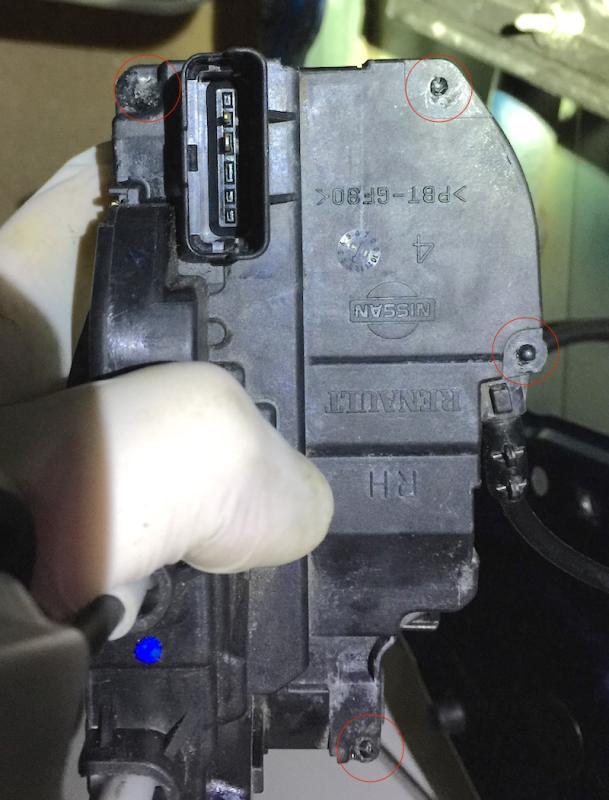
Step 2 – Once you have removed the inside panel, you should have access to the door lock actuators. Unscrew the three screws that told it in place:
Step 3 – There is a wire connector on the actuator, remove it by pulling, NOT PUSHING the connector tab
Step 4 – You can immediately take the actuator apart even though there’s still a cable connected to the door handle. Start by removing the heat sealed pins with a wire cutter but DO NOT cut the whole pin off. Just squeeze lightly at the plastic around the pin then pry upwards, and the melted plastic should pop off as a ring.
Now use a screw driver and carefully pry open the retainers on the sides of the actuator. Takes a bit of elbow grease to pull the cap apart, but there’s no trick to it. Even if a tab or two breaks, you can still glue things back in.
Step 5 – Once the cover is off, confirm that the door lock in in fact working by pulling and pushing the cable that connects to the door lock. The end of that cable has an L shaped pin, not the ball shaped joint.
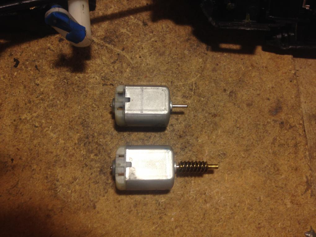
Then it’s time to replace the motor. You’ll see the motor that’s attached to the actuator’s cover. It comes off easily by prying with a screw driver. The trick now is to pry off the worm gear from the motor and attach it to the new one. You might need to cut the shaft off the new motor to make things work. Sorry I did not perform this step as I ended up fixing the motor itself.
Step 6 – (optional) Fix the motor if you’re a cheap bastard and don’t want to spend the $5. With your pliers, pry open the side tabs that are holding the end cap. It helps to mount the motor on a vise.
Once the end cap is off, clean the brushes with brake cleaner or alcohol, then remove and wrap the thermo protection plate with aluminum foil. This will make the motor work again, but now the motor can potentially burn up if the lock is stuck. I didn’t know the motor’s size until I opened the actuator, and now I don’t want to wait for one to ship, so I went with this cheap route. For the rest of you, I highly suggest spending that $5 and have a new motor ready before you start.
If you have a 12v power supply, feed 12v directly to the motor on both polarities and make sure it’s working.
Step 7 – Time to put everything back together. I suggest using some glue on the pins of the actuator, or even on the sides of the casing. Try flexible glue like Goop or Gorilla glue.
Step 8 – Test for functionality. Connect the wire harness to the actuator and try locking/unlocking with the remote. The wire that goes to the door lock should pop in and out. If it’s not happening, chances are the white plastic tab inside the actuator is out of place and it’s a simple fix.
Step 9 – Install the door lock actuator back. REMEMBER TO CONNECT THE WIRE HARNESS!
Step 10 – Install door panels. In the door panel removal video, the tech installed the power window unit before installing the inside door panel, but you can save time by just putting the inside door panel in place and then screwing the power window unit back on. Start with the power window motor. Put one hand behind the panel to guide the motor so the holes align. After you screw the bolts in by hand, guide the power window rails in a similar fashion. Might take a bit of pushing but it’s very straight forward. As soon as the inside panel is installed, test your window and make sure it’s working.
FINISH
Hope this help whoever’s having problems with their locks. Compared to fixing that damn transmission issue with the valve body, this is a cake walk. Big thanks to all the people who committed to those threads by helping me fix my transmission without having to spend thousands!
Cheers,
-Derek
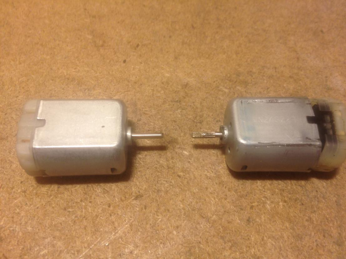
Additional Specs & Photos of Actuator Motor by EddyMaxx
Specification:
-MPN: FC-280PC-22125
-Model: FC-280
-Dimensions (not including shaft): 30.5mm x 24.2mm x 18.3mm
-Round shaft dimensions: 9mm long
-Operates on 12 VDC nominal
-No load speed: 13,100 RPM
-No load current: 110 mA
-Recommended operating voltage range 8-16V DC
-Quantity: 1 pc
Below is the information seen in the Nissan factory service manual (FSM) for 2002-2008 VQ35DE Nissan Maxima’s. This information can be found in the “ENGINE LUBRICATION SYSTEM SECTION – LU” section of the factory service manual.
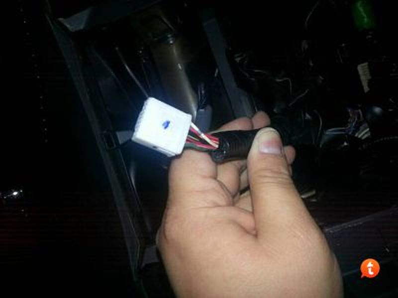
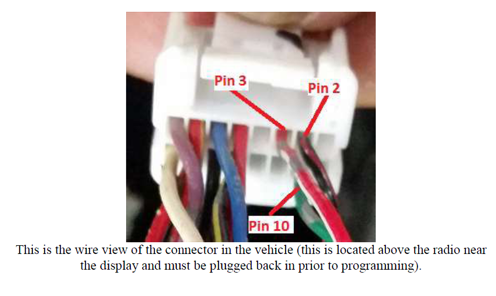
This is the installation of the Axxess ASWC-1 aftermarket steering wheel controls on my Pioneer Headunit in my 2004 Nissan Maxima. I did this write up to document my installation and hopefully help some my6thGen.org forum members clarify the installation process.
The ASWC-1 adapter from Axxess allows you to connect your vehicle’s steering wheel controls to almost any brand of aftermarket stereo, including Alpine, Clarion, JVC, Kenwood, Pioneer, Sony, and more. (Note: your new stereo must have a 3.5mm steering wheel control or wired remote control input.)






























































 With your pliers, pry open the side tabs that are holding the end cap. It helps to mount the motor on a vise.