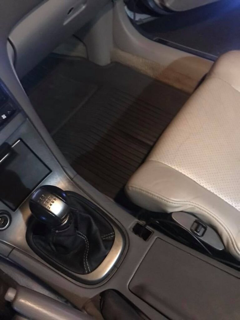
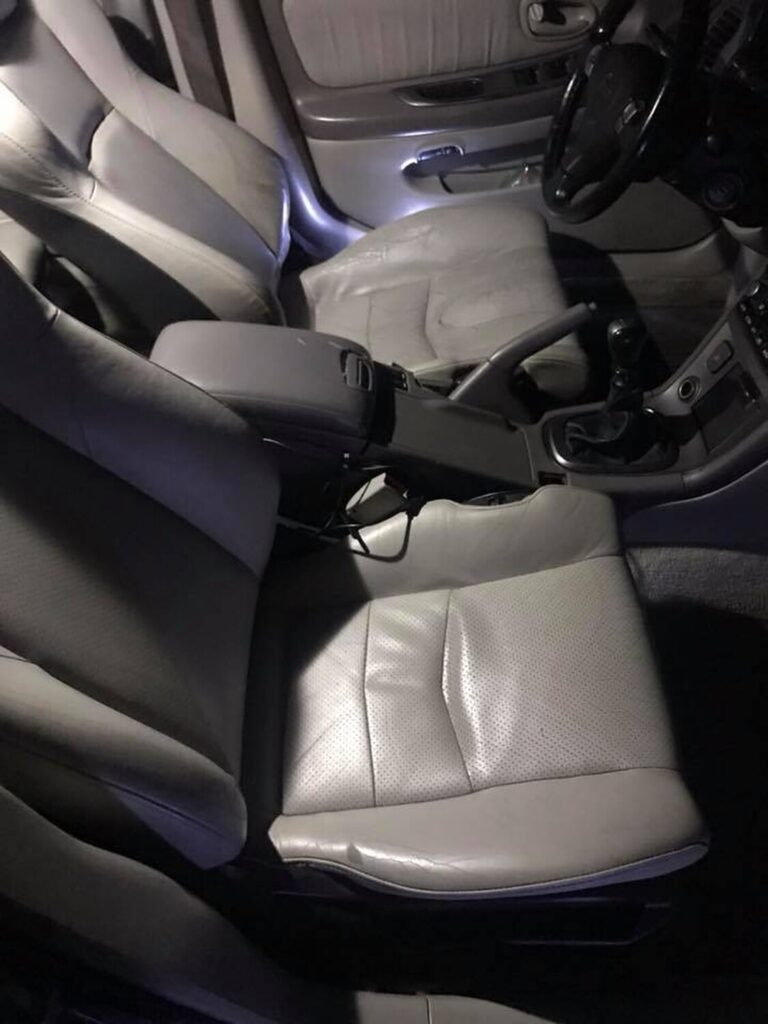
Community Member Credit: Jared Floyd
PC Mod Link: https://www.gta5-mods.com/vehicles/02-03-nissan-maxima-5-5gen-add-on-replace-tuning




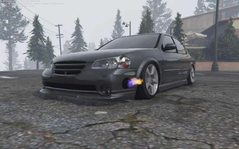
Community Member Credit: Jared Floyd
PC Mod Link: https://www.gta5-mods.com/vehicles/02-03-nissan-maxima-5-5gen-add-on-replace-tuning
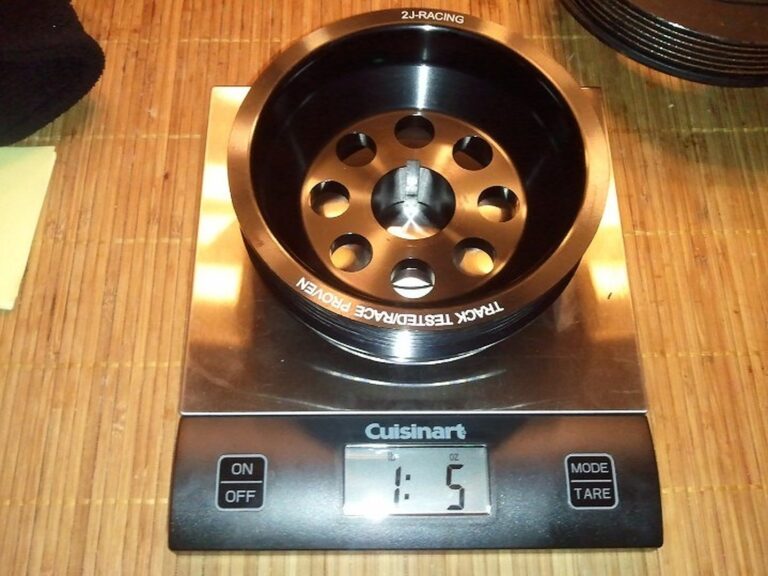
Order Link: https://www.2j-racing.com
Price: $99.99
2JR introduces our lightweight race pulley for the VQ35 Maxima and Infiniti I35, 01-04 years. Based on a far better design than the OBX pulley with a 75% weight savings over OEM, this is a must have mod for your VQ. Gain upwards to 9WHP / 12WTQ. Offered ONLY in anodized BLACK, with 2JR Logo.
2002-2006 Maxima Belt Size
2007-2008 Maxima Belt Size


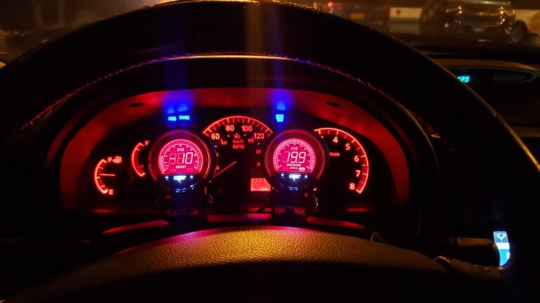
Community Member Credit: Jose Vargas
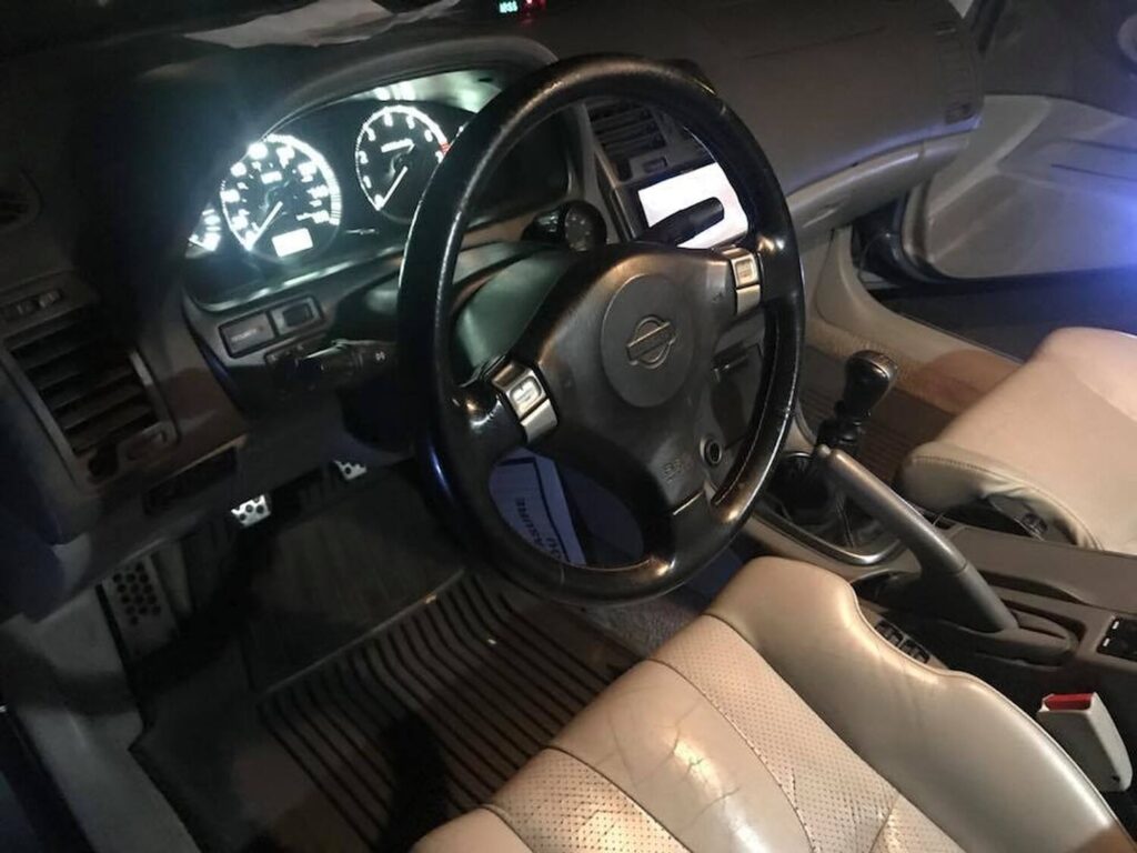
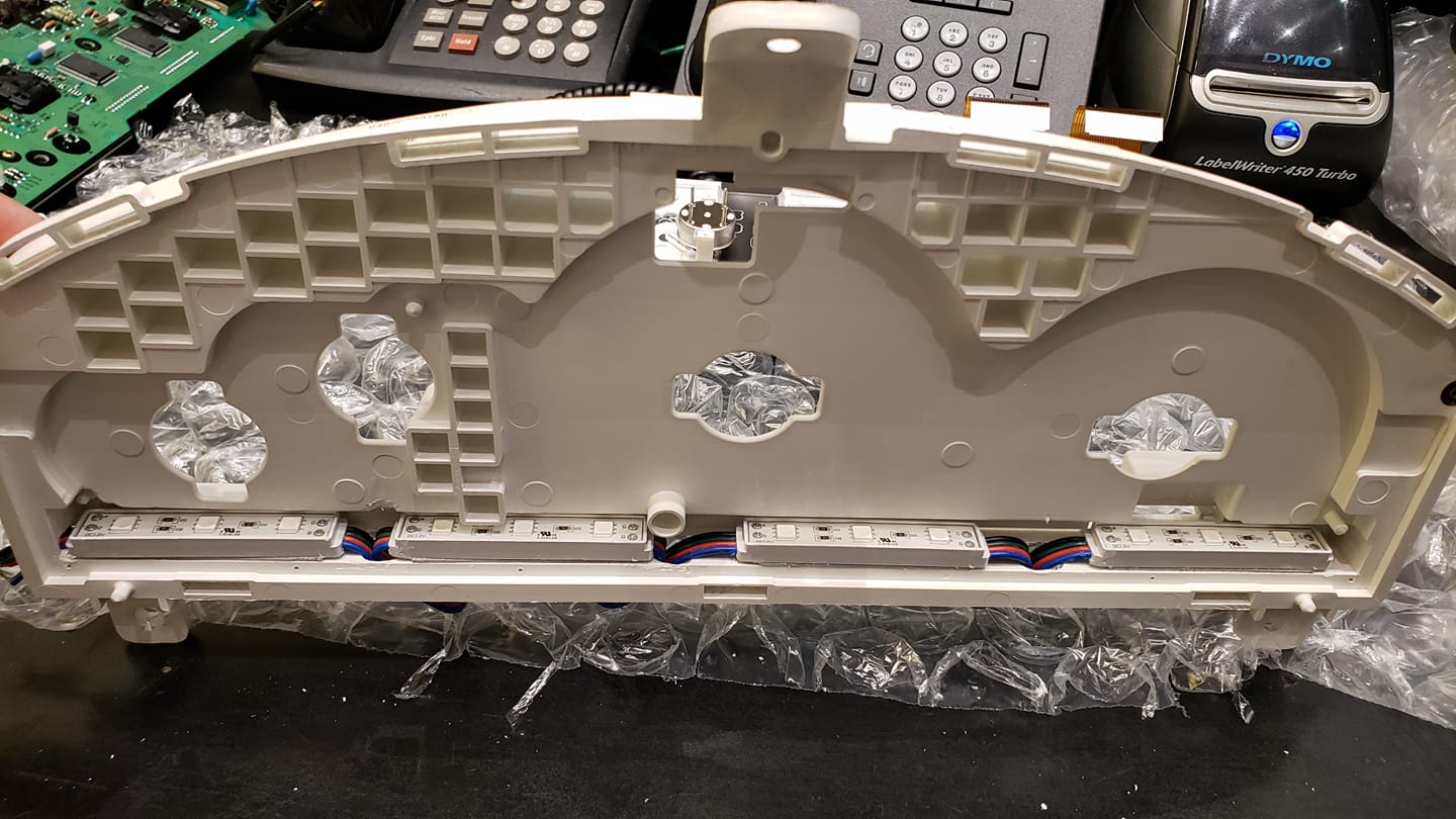
I35 Cluster swap in the process, first ima swap out the long led tub it has to light up gauges and replace it with 4 RGB led strips with the module so I can remotely change to different colors quickly if I want to. Everything PNP like OEM. I’ll post links to what I used to make it perfect…

Has 4 pnp leds that can easily be swapped and for warning indicators you need to unsolder old leds and put in new ones 14 is needed

For the Auto guys you can swap out the shift indicator leds……..3mm for warning indicators,so since the cover and holes for leds is big enough im a swap out the 3mm to 5mm to have it brighter

Without OEM led tube

With oem led tube that lights up entire cluster, so as you see you can run strips

You need 4 strips of these RGB leds
https://www.superbrightleds.com/moreinfo/led-module-strings/rgb-led-modules-linear-modules-w-3-smd-leds-22-lumens/1779/4253

Female……Pigtail connector to make it pnp to module
https://www.superbrightleds.com/moreinfo/bar-strip-connectors/lc4-locking-connector-pigtail-power-cable/1972/4547

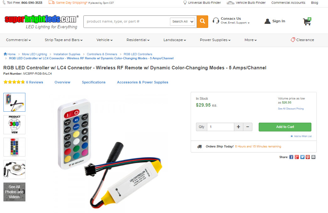
Module with remote to change to multiple color
https://www.superbrightleds.com/moreinfo/rgb-led-controllers/rgb-led-controller-w-lc4-connector-wireless-rf-remote-w-dynamic-color-changing-modes-5-amps-channel/3050/6263
Male Power connector to make it pnp, run ground to chassis and power wire with mini add a circuit with 15A fuse to ACC in fuse box
https://www.superbrightleds.com/moreinfo/bar-strip-connectors/cps-f2st-female-standard-barrel-connector-to-screw-terminal-adapter/856/2133

I35 cluster 80% done installed the leds strips. Just waiting for module and pigtail to make it pnp……

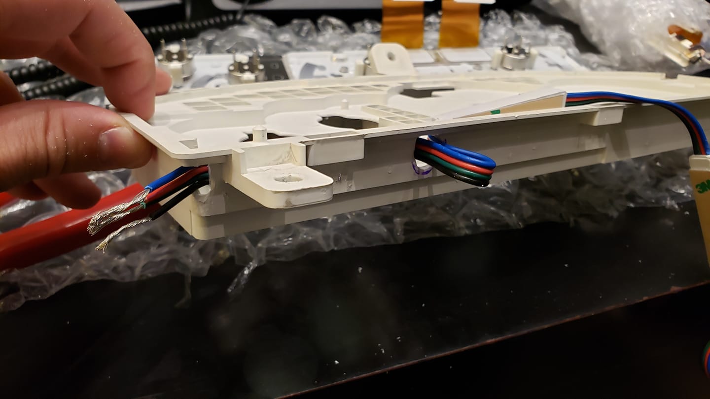



Swapped out the 5 pnp leds
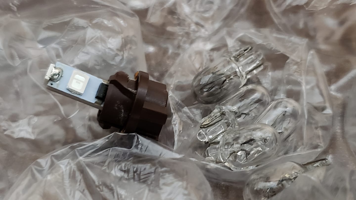
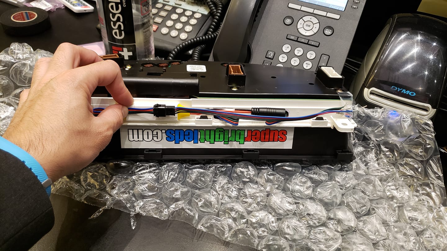


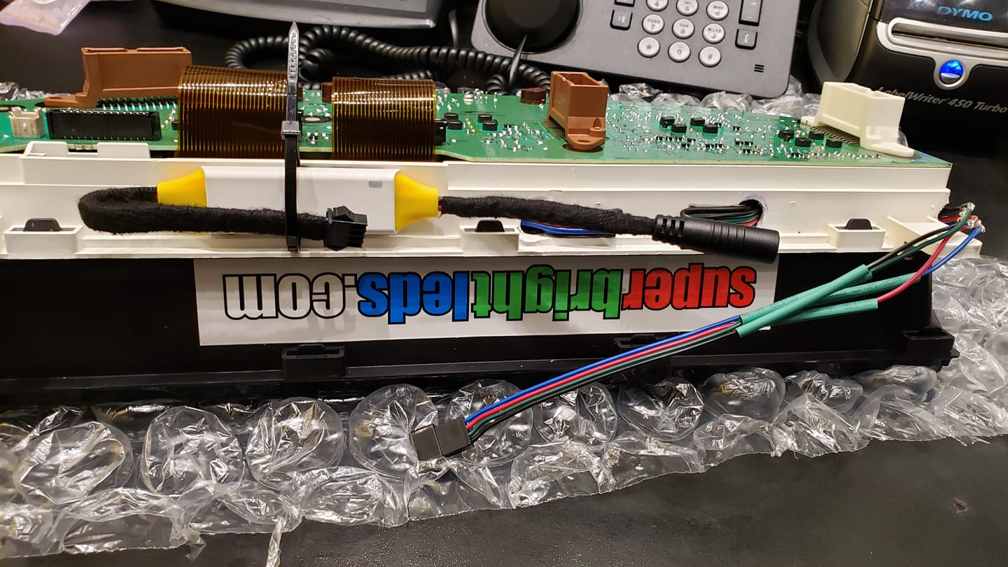


5mm to the left soldered in compared to the small 3mm to the top right
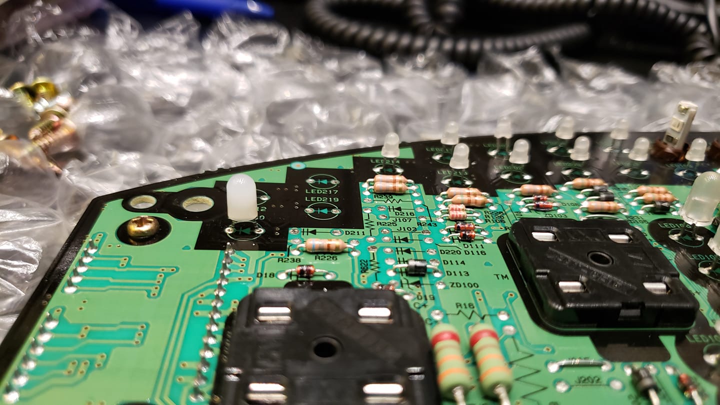
 5mm vs 3mm

Removed SLIP led so it will not turn on LED213.

Cluster done
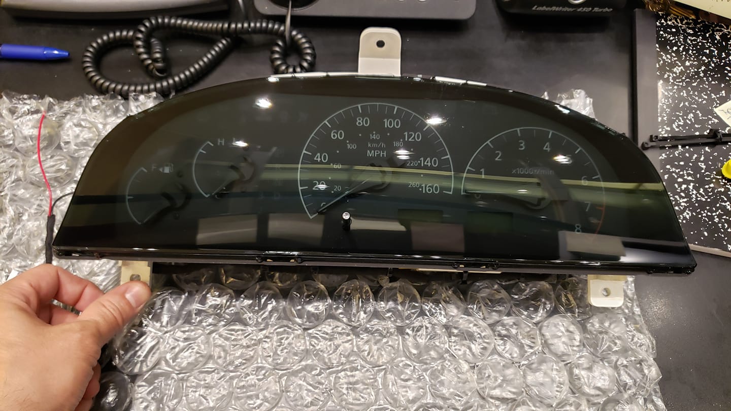

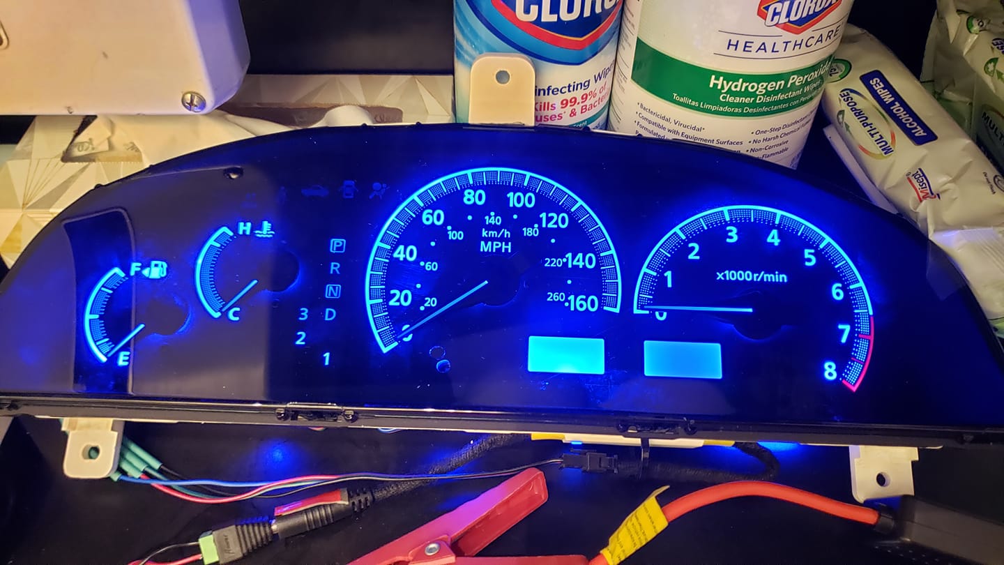
Had to dissamble the cluster to put black tape over the AUTO indicators

5MM led clearance
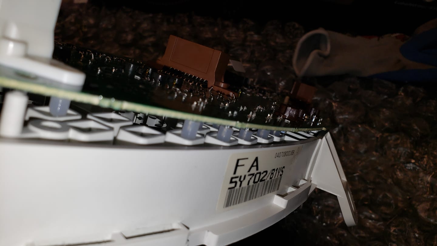
Pnp connector all wired up and ready. Nice and clean…Mr. DoITRightEveyTime.


Cluster is done and installed……mission was a success…..Repinned the plugs and rewrapped harness

1 done 2 plugs left

Wiring mess
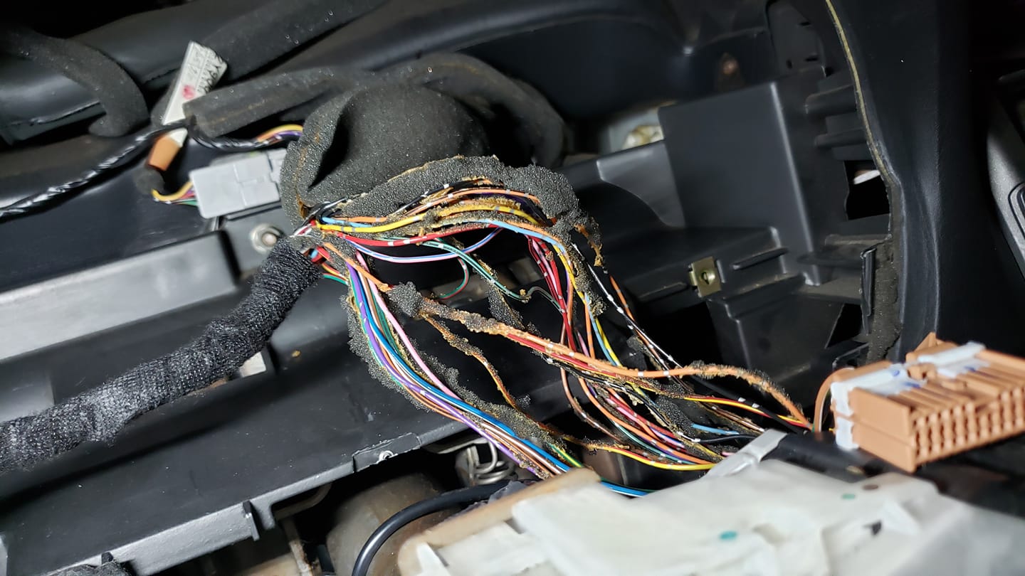

3 plugs all wrapped up

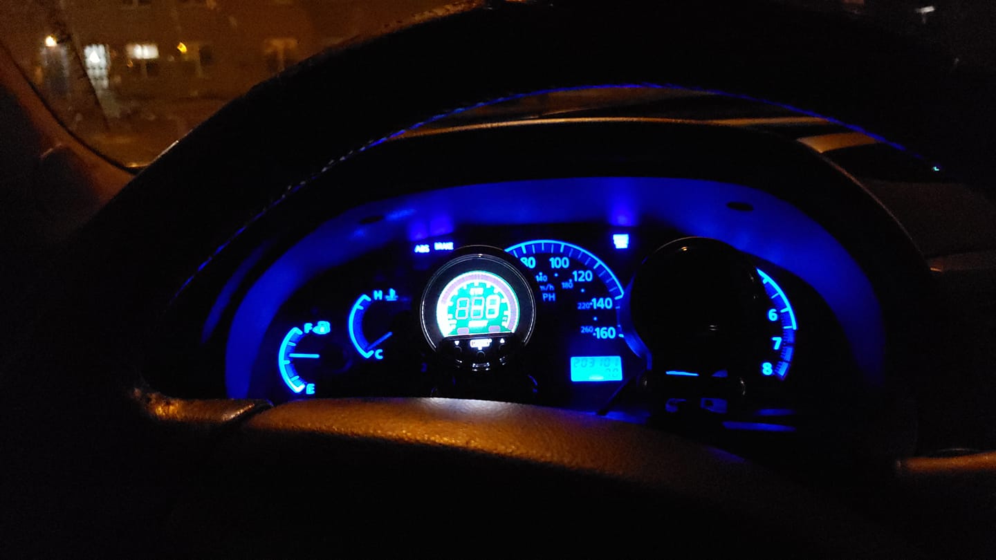
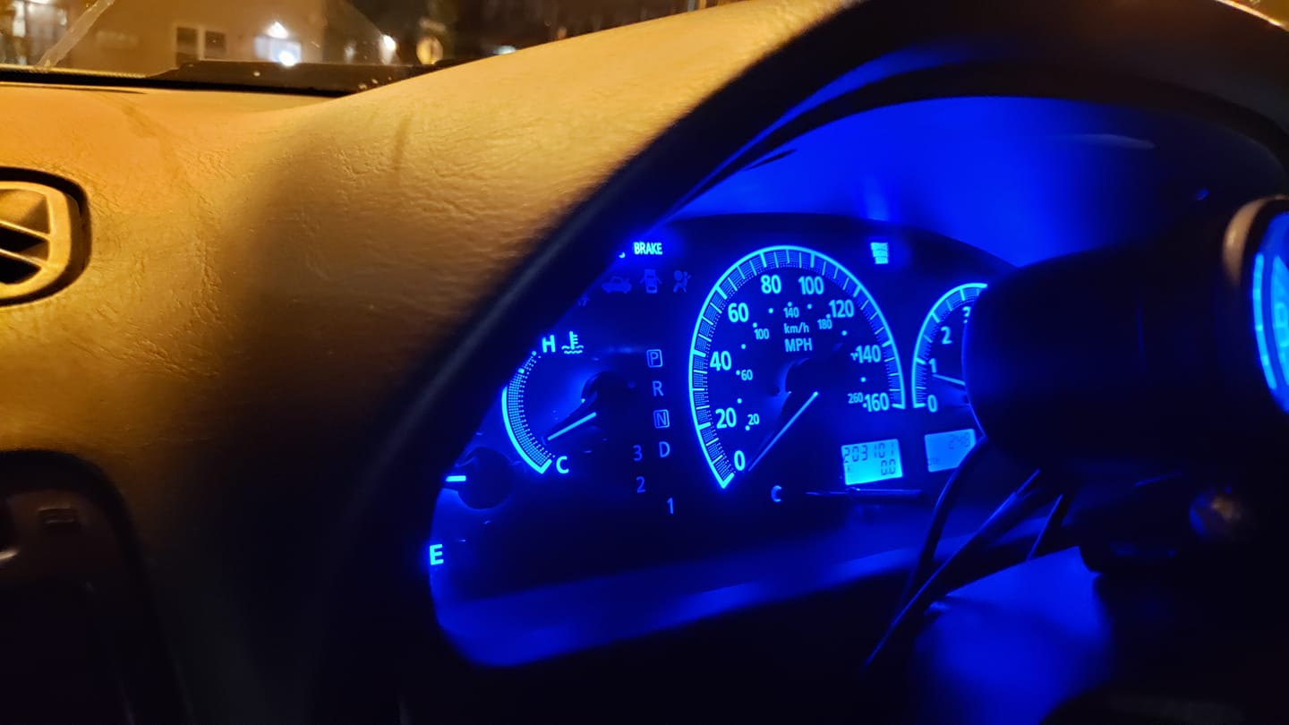

I35 Cluster & Prosport EVO series allows you to match up 4 different colors to cluster..
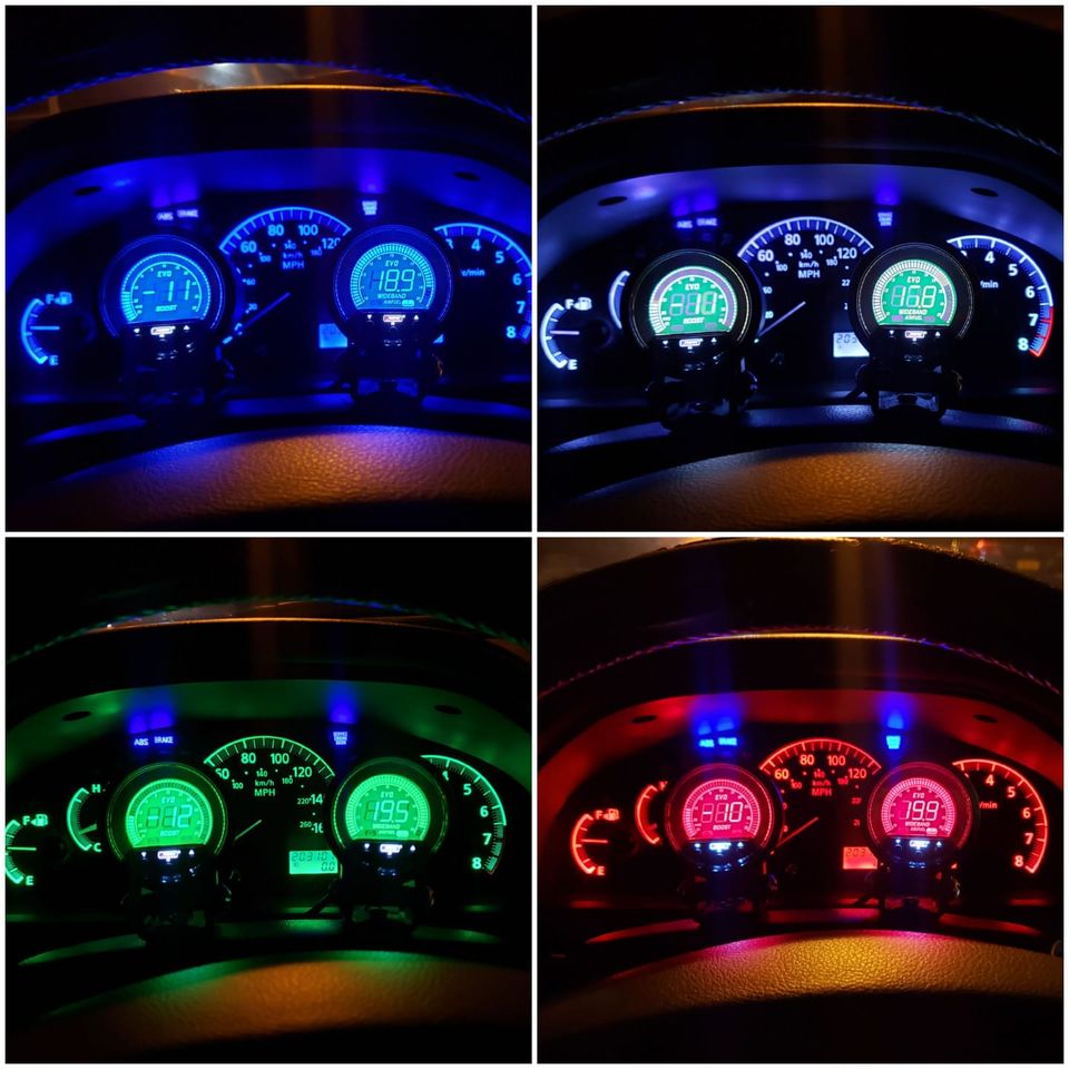
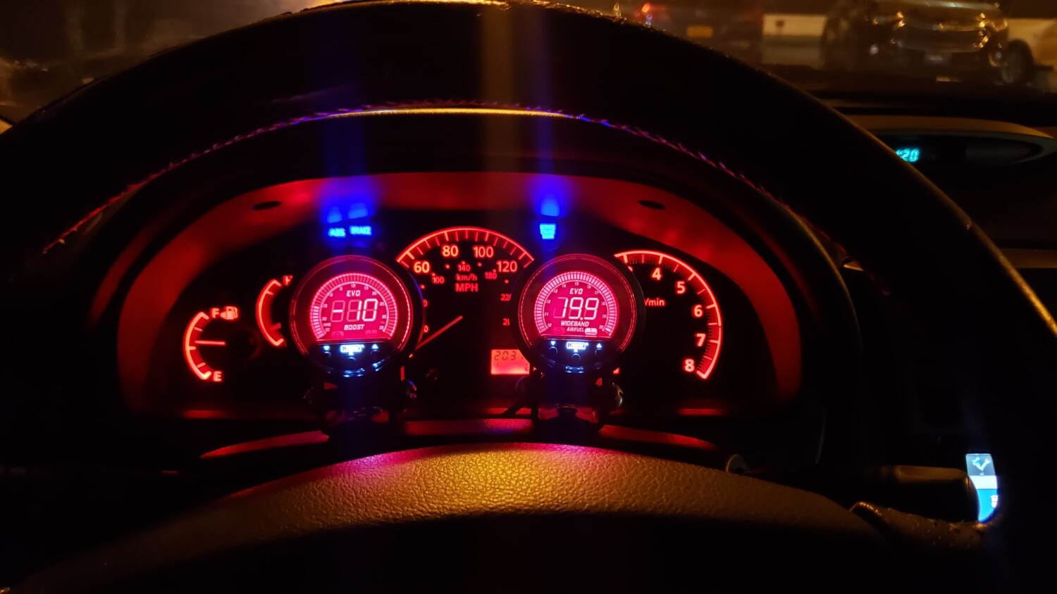
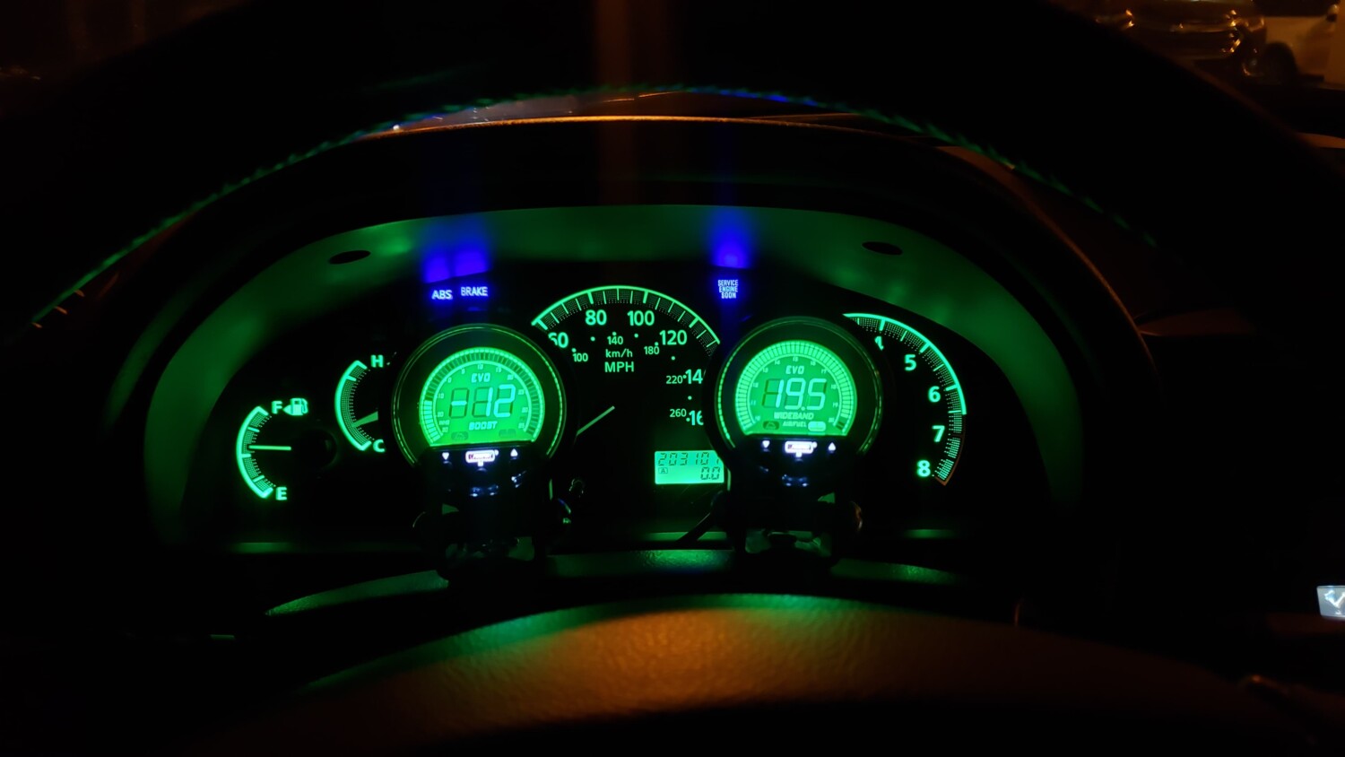


Credit: 02whitemaximase
The OBX headers (02-03 Maxima, equal length y-pipe) have been out of stock for at least a year. For engine performance mods I have the Megan OE-RS Catback installed along with berk/Apexi intake and 5 piece spacers. I have compiled all of the information needed to get these headers installed correctly.
My first photo is of new OEM exhaust gaskets. Look at the part numbers and order those if you plan on doing a header install on a 3.5. Although you could get away with reusing the original gaskets, I would recommend spending 35 bucks for peace of mind.
The front (closest to the radiator) header measurements are as follows:
Runner length from where it meets the flange to where all three join cylinder 2= ~10″, 4= ~9″ 6= ~12″
Prices and part numbers:
The purpose of this thread is to display the newest batch of OBX headers. Exhibit how the install goes and post up some before and after pictures and videos.


My install went nearly flawlessly minus one heat shield bolt being seized and a secondary o2 sensor not coming out of the old converter. I know these headers are made overseas where quality control is not great. With that being said I think no two sets of headers are exactly the same which means that you may need to trim something during your install. I came to a couple of millimeters from having to trim my front motor mount bracket and my rear bracket went on no problem although it was very close. Probably about 2-3 mm from touching and my front bracket is literally 1mm from touching the header. My flex pipe has about 1/4′ space from touching the subframe.
As you can see one of the primaries comes very very close to the front motor mount bracket but it did not require trimming. Although some may be uncomfortable with how close they are, it is no problem. The mount and header will NOT move even though mine are basically touching it does not matter.

The y-pipe comes about 1/4 of an inch from touching the sub-frame cross member. Again this is not a problem. I have driven it like this enough to not experience any noise and the way I see it the motor really only moves front to back so this tight space does not come into play.

In order for the front primary to have enough wire slack to reach the new header bung, you will have to cut the tape holding the group of wires that travels directly over the middle coil from the larger harness that runs along the top of the valve cover. The tape was holding both harnesses together to about right in the middle of the top middle of the valve cover. Easy fix takes one second.

As you can see below the far left plug has to be unclipped from the coolant pipe in order for that primary to reach.

The rear primary wire has to be extended too. From all of my research people here have been saying to cut the primary either at the wire harness and add some wire to lengthen it or to cut the actual o2 wire and extend those by adding wire. Problem is that it can mess with the voltages. The wire is stainless steel which is nearly impossible for an amateur to solder correctly. My method requires NO WIRE CUTTING!!! You need to remove the wire harness cover pictures below and simply separate the o2 wires from the rest of the wires. First, you need to separate it from the green plug wires, then you need to slit the right side of the main harness that fees into the back of the plastic box. PLEASE TAKE YOUR TIME!!! Be very careful to cut precisely and slowly. Doing this will give you enough slack to reach the rear primary o2 sensor.

This next picture shows exactly where my o2 wire is coming out of the main harness. It is wrapped in a black plastic protector. This picture is taken along the firewall from the driver side, so the top of the picture is the passenger side, the bottom is the driver’s side and as you can see the top left is the upper part of that black wire harness box. The fattest harness coming from the box is what you need to slit the side of and separate the 02 wire from. My o2 wire is running out of that harness down toward the middle of the picture.

The following picture is of one of my secondary sensors. I have the antifouler setup and as of about 75 miles no CEL. This secondary is the one with a green plug and red wire cover. The wire running above it is actually the other secondary which is the blue plug with a white wire cover. Secondaries have different length wires so I recommend this configuration.

As you can now see the y pipe outlet is not quite at 2.5″ but pretty damn close

My new wideband bung on the y-pipe.

The relocated rear header primary bung and plugged original location


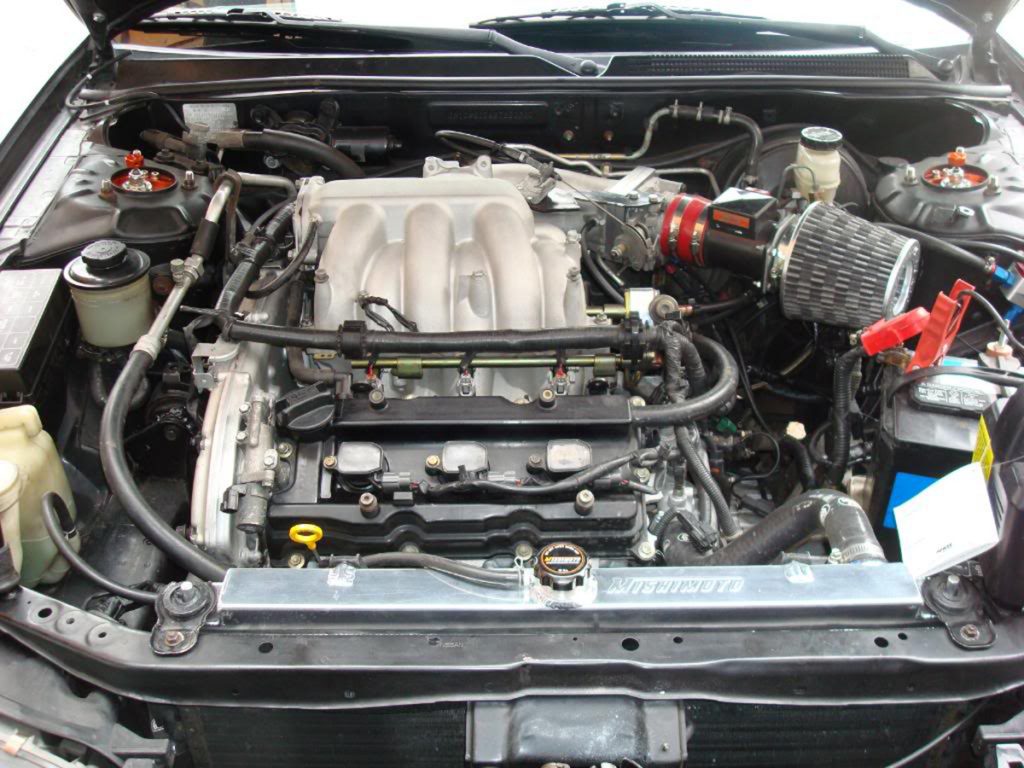
Community Member Credit: Tavarish aka Freddy (nycmaximas)
So you’re ready to get rid of that old outdated 3.0 and put in a brand spanking new low mileage VQ35DE? You’ll have to get a few things before you start the swap.
Tools – I suggest about 2-3 sets. With tools scattered around everywhere, and possibly 2 people working on the car, tools have a tendency to disappear. (gremlins) Have a few sets handy for efficiency and less frustration during the swap. When you clean up, you’ll find them all, I promise. What you’ll need is a torque wrench, breaker bar, screwdriver set, Allen key set, 8mm, 10mm, 12mm, 14mm, 17mm, 19mm, 20mm, and 24mm sockets. Air tools are a plus. You’ll also need a cherry picker (engine hoist) with an engine leveler. A Dremel (rotary tool) and Drill are worth their weight in gold in this swap. Jack stands and a hydraulic jack are needed to lift the car up, and possibly support the engine/tranny from the bottom. Also needed is RTV sealant, wire ties (to clean up wires, vacuum hose, a can or two of WD-40, and 80-grit sandpaper.
Space – you’ll need space to work for a few days, make sure it’s ready in case you spill oil or other fluids on the ground, engines tend to spill coolant all over.
Clean-up gear – I suggest brakleen for the engine parts (degreases) and Simple Green. Put some old towels underneath the working area to control any spills. Wear gloves for easier hand clean up, I recommend Mechanix gloves, or disposable latex gloves. A shop vacuum helps with cleanup as well.
Manuals – The Nissan Factory Service Manual and Haynes were at my disposal, and helped me out in a few instances.
Engine – You can find these pretty easily; it all depends on the mileage you want, and the condition, and what the engines come with. I bought my engine for $650 shipped with harness and 3.5 engine cover, and a 1-year warranty.
Tranny/clutch – you can use your stock 5spd or auto trannies. 5spd, I recommend an upgraded clutch, I got my Spec Stage 2 for $295 shipped. 5th gen (2000-2001 OEM isn’t enough in my opinion) You can use any flywheel for the 4th gen, stock or aftermarket, and you’ll need it, because the 3.5L flywheel is different, and doesn’t bolt up to the 4th gen 5spd. Auto, I recommend a high-stall torque converter, upgraded valve body, tranny cooler, and possibly Jime’s drop resistor mod. When you have a vq35 and auto, it will hold the power if you floor it FROM A STOP. If you have a stock auto tranny, do not WOT downshift much, or else you’ll burn out your clutch packs and the tranny will slip.
Cam adapters – These are so the vq30 timing components work on the vq35 cams. You can get these for 100 shipped from Rob Tilley (tilleys99 on maxima.org), or Stephen Max on maxima.org. I’m trying to make my own set, so I don’t have to go to a third party to get them.
IACV adapter – This is so you can use your 4th gen Idle Air Control Valve with the 3.5. This is optional, as I don’t have it installed on my car.
If you have everything ready, let’s start the swap!
Turn off the car, remove the battery terminals and any extra grounds you may have.
Remove the air box assembly and put it in a safe place, you might want to use it again.
Under the air box assembly, you’ll see the starter connected to the tranny. Undo the 12mm nut connecting the power to the starter, and disconnect the ground for the starter (plug). Loosen and remove the 2 17mm bolts on the starter. The bolt in the back is the long one. You should be able to shake the starter loose and take it out of the engine bay.
Raise the car and place it on jack stands. Remove both the front wheels. Remove the 36mm axle nuts (air tools are pretty much a must, as you can remove it with a lot of WD-40 and a breaker bar, but you need the brakes to be pressed or else the axle will move) and remove the 2 bolts on the strut. One side is 17mm; the other side is 19mm.
Use a flathead screwdriver to lightly tap and take off the retaining clip on the brake line located on the strut. If you have ABS, take off the 10mm bolt on the strut for the ABS. The spindle should come down freely now, and with a rubber mallet, tap the axle out of the spindle. The driver’s side axle should come out without too much fuss, just pull it back a few times, and it should pop right out.
The passenger’s side has been a point of frustration for many people, due to the axle not coming out of the bracket. I’ve never had a problem with it, but the bracket holds 3 12mm bolts. Take these out, and you should be able to pop out the axle just like the driver’s side. If it won’t budge, take out the 3 14mm bolts attaching the bracket to the engine, and the whole assembly will come out. Make sure you have something to hold the oil; some tranny fluid will leak out of the axle seals.
While you’re down there, why not drain the oil and coolant? Remove the oil drain plug on the oil pan, and remove the oil filter.
Remove the radiator drain plug (Philips head screwdriver), and drain the coolant. Remove the 2 10mm bolts on top, disconnect the hoses from the engine, and remove the harnesses to the fans, and slide the radiator out of the engine bay.
Drain the tranny fluid, there’s a spot covered with a 10 mm bolts, connected to the shifter indicator pull it out, and the whole tranny should drain.
Now it’s time to remove the harness. Remove all the sensors in the engine, and put them to the side. There will still be a harness at the back of the engine, but we’ll keep that on for now, it’s the injector sub harness.
Remove the power steering lines; disconnect the one from the pump to the reservoir, making sure to have a rag to soak up the runoff. Also loosen the 24mm high pressure line for the power steering. This bolt is a bit stubborn, but it’s definitely able to loosen. Make sure not to lose the upper and lower gaskets for this bolt, because power steering leaks aren’t the prettiest.
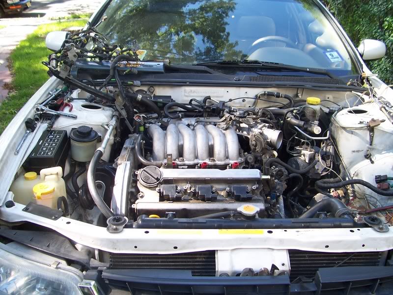 Remove the O2 sensors (I use a 7/8” open ended wrench) and remove the y-pipe. There are 8 bolts, 14mm if you have an aftermarket y pipe (as you should), and 10 bolts, 8 14mm, and 2 12mm bolts holding in the y pipe.
Remove the shifter linkage (5spd) bolts on the bottom of the tranny, and let the shifter linkage hang there. If you have an automatic, remove the 2 shifter cables from the front of the tranny.
Taking advantage of being under the car, you can loosen and remove the 14mm bolts on the bottom of the tranny. There’s one 17mm bolt all the way in the back of the tranny, it’s kind of hard to spot, but you need to get it out. The bottom 14mm bolts can’t be taken out (crossmember’s in the way), but you can loosen them enough to take the tranny off. Get out from under the car, and remove the remaining 17mm bolts on the top of the tranny, you can remove these very easily with a breaker bar or air tools, you’ll have enough room. Now it’s time to support the tranny with a hydraulic jack (or engine hoist if you are so inclined, as was I) and take off the mount bolts (14mm). Use a flathead screwdriver to get in between the engine and tranny, and pry until the tranny is loose, then ease it out and lower it down, out of the car.
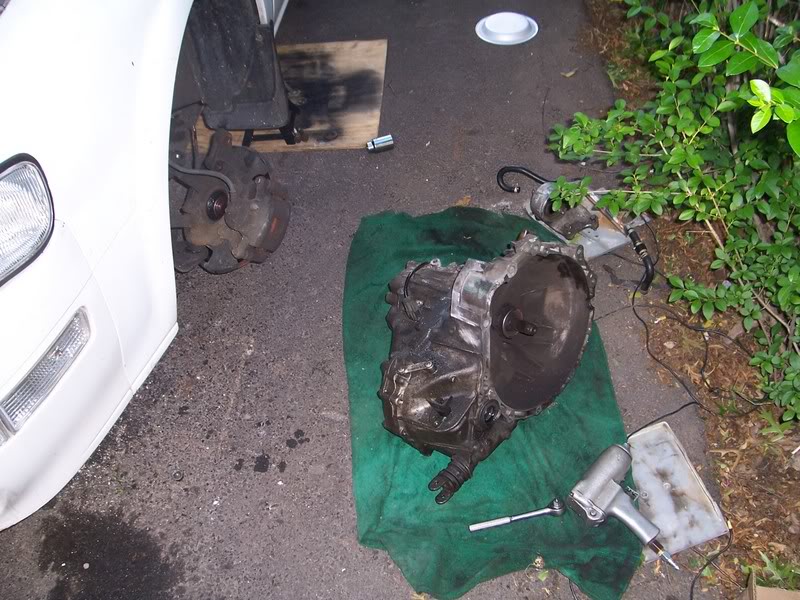
Next, disconnect the feed and return lines for the fuel, and disconnect the coolant hoses coming from the firewall. It’s easy to do this from the side of the engine.
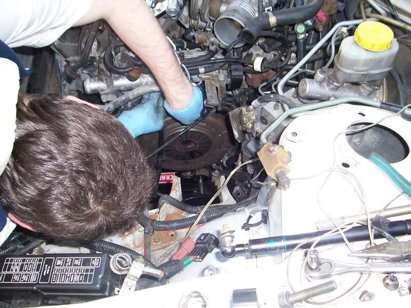
Now here’s the (first) fun part: taking out the VQ30DE!!!!
Get your cherry picker engine hoist. Hook up the engine leveler to the engine. Here’s what I did. There are 4 points of contact. Bolt it onto the 2 14mm bolts on the timing chain cover, right above the motor mount, and the remaining two, bolt them onto the 17mm bolts for the transmission bellhousing. This should provide a pretty sturdy base to hold the engine. Make sure no fuel lines are kinked, and make sure there is ample clearance for the chains, and none of them bind.
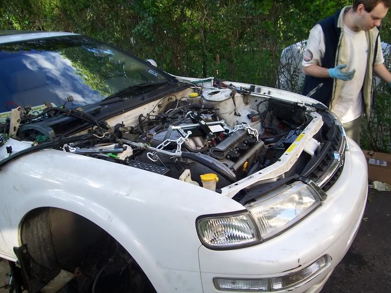
Connect the cherry picker, and apply just enough pressure to hold the engine without it falling. Now, some brave soul (me) must go and disconnect the 17mm bolts that hold the crossmember on. Also, remove the 17mm motor mount bolts. Use a LARGE breaker bar, on in my case, a good impact wrench. There are 2 17mm bolts in front for the crossmember, and 2 in back. Be careful that you’re not underneath, it’s pretty heavy. When you disconnect all motor mounts and the crossmember, move it out of the way. You’re almost there. Well, almost halfway.
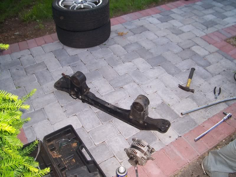
Disconnect the 14mm bolt and nut from the remaining motor mount, and now the engine should be entirely supported by the engine hoist. Carefully lift it up, making sure that it is not binding anywhere. You don’t want the engine falling. Lift it until you can roll the engine hoist out of the way.
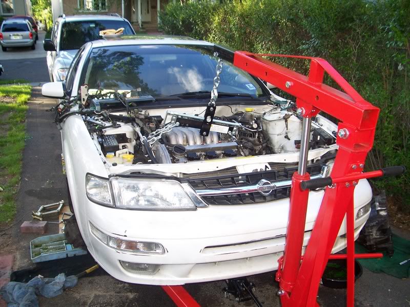
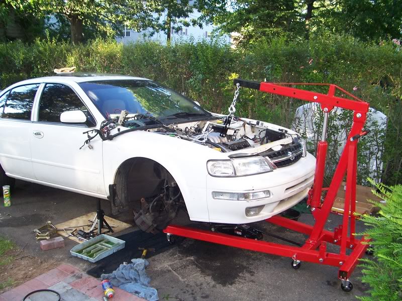

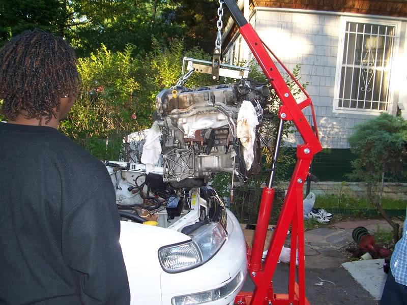
Put the engine down, and take a break and get a drink. You just took an engine out of a Maxima.
Here are the meat and potatoes of the swap: Changing out the timing components.
The first thing to do is remove the engine mount that sits on the timing cover, the crank pulley (20mm), and remove the various 10mm and 12mm bolts that there are. To fully remove the timing cover, you need to remove the lower oil pan, (all 10mm bolts), but be careful that you pry with a very small flathead screwdriver, and make sure not to dent. This can leak VERY easily if it’s dented and it goes back on the car. You can use either the 3.5 or the 3.0 lower oil pan (just the drain plug is different), it doesn’t matter, so if you mess up and kill one oil pan, don’t sweat it, just don’t do it again.
When you remove the oil pan, there are 2 12mm bolts holding the inner timing cover on.
Remove these, and pry the outer timing cover off. I recommend using a pry bar on the side where you can get some leverage, and be very gentle. Although it is aluminum, it can easily crack. The factory sealant that Nissan put is very strong, so give it a good 5 minutes of work to completely remove it. There are 2 dowels at the bottom of the timing chain cover that you need to clear for it to come off. It must come off these dowels at exactly the same time.
When the timing cover comes off, it should look like this:
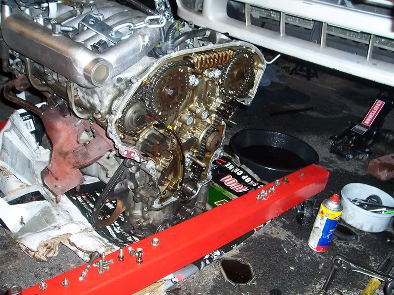
Now we’ll take off some timing components.
To take off the main timing chain sprockets: open the valve cover (front one will do for now), and hold the intake cam with a 1” open-ended wrench. Use a 22mm open-ended wrench to take off the bolt. This bolt is TOUGH, but do not use air tools on it. I cracked a cam before, they can be pretty fragile. This part it’s a lot easier to do with 2 people (one loosening the bolt, the other holding the cam.)
Once that’s off, you can take off the chain guides (12mm bolts), and the other cam sprocket in the same manner. Then you can take off the chain. Make very sure of where you put these parts. After you remove the timing chain, you can remove the water pump, which is held on my 3 10mm bolts, and be careful, when you pry it out, a lot of coolant will flow out. Also, take off the tensioner (2 10mm).
*Side note: You will want to take off the intake manifold to gain access to the rear valve cover, so go ahead and get that out the way. You can cut any vacuum lines, you won’t be using them again, and it’ll be a lot easier. The hardest part about taking off the intake manifold is the removal of the throttle body. It’s connected to coolant hoses, vacuum hoses, and all these will need to come off in addition to the 4 10mm bolts that are on there already.
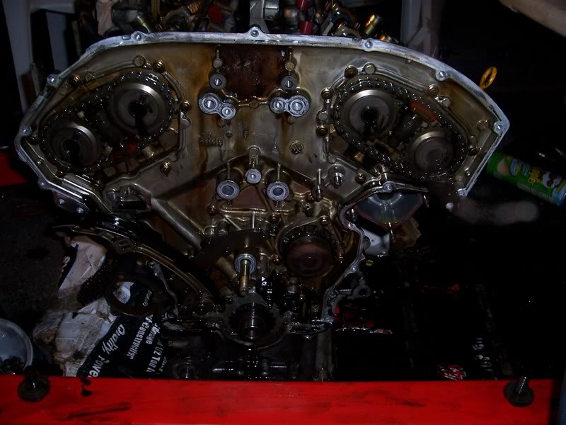
Now we take off the secondary cam gears (exhaust cams). This is a 17mm bolt, and it comes off exactly the way the other ones did.
Now that we have the cam sprockets loose, squeeze the tensioners and hold them there with a thumbtack or small nail (there’s a little hole you can squeeze it into and hold it in place). Now you can simply pull out the cam sprockets from the cams, and the secondary chains with them.
Remove the various 10mm bolts that hold the inner timing chain cover on. Also remove the pieces that go in between the timing cover and valve covers, there are 4 10mm bolts on each.
Remember where you put all of these **VERY IMPORTANT**
Now you can pull off the inner timing chain cover. Use a pry bar, using any points of leverage that you can find. I found the inner timing chain cover was a bit easier than the outer.
Now that you have the VQ30DE taken apart, you guessed it. You have to do the exact same to the VQ35DE. First, make sure the engine is at TDC (top dead center). The way to do this is to line the crank pulley (second mark) with the mark on the water pump drain back plate. This is also explained more thoroughly in the FSM.
I’ll save some space, since it’s the exact same procedure, only the intake cams need 19mm bolts, rather than the 22 on the VQ30DE. The procedure for taking apart the engine is almost exactly the same.
When you’re done with stripping the VQ35DE you’ll end up with something like this:
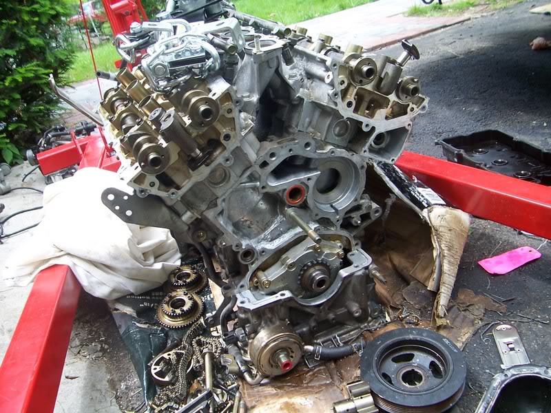
Here’s where you have to CLEAN, CLEAN, CLEAN!!!
Take out your gasket scraper and cans of brake cleaner. Scrape off every last speck of factory sealant (from the block and both timing chain covers) with the scraper (you’ll go through a few blades), and be sure to get in every nook and cranny. A sharp knife will work in places the gasket scraper can’t get to. When everything’s off, go over it a few times with the compressed brake cleaner (it’s non flammable and dries fast, but the cans get used up quickly.)
Mount the cam journals (thing in between the timing cover and valve cover) from the 3.5 on the engine, then test fit the timing cover. There should be two bolts out of place. This is where you must drill to ensure the bolt goes through. Only a small amount needs to be taken away. Make sure you clean any metal fragments that remain on the inner timing cover. While you’re on this step, you can install the cam tensioners from either the vq30, or the vq35, they both fit.
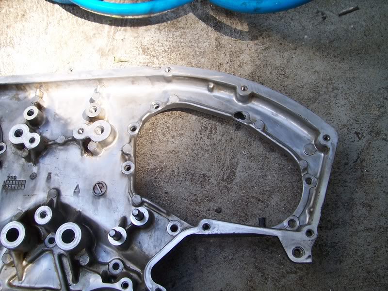
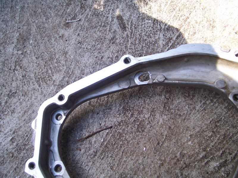 Make sure you have The O-rings on the engine (the orange ones) before you put on the timing cover. I used Black RTV sealant, and applied a nice, even bead so it doesn’t puddle up and make a mess in places. Oil leaks are the last thing you want when this thing goes together.
Put sealant everywhere designated. If you don’t know where, consult the FSM, but it’s pretty self explanatory. Any small, smooth surface needs sealant. Double check you have everything properly covered with sealant, then *carefully* place it on the engine. Now you secure it with the 10mm bolts. The tightening sequence is pretty important, and you have to torque them down to 10-15ft-lbs. The tightening sequence can be found in the FSM.
After you have the inner timing cover, comes the hardest part: setting the timing.
Get the cam adapters and gently tap them on (the set I got needed some slight grinding with my dremel to make them fit.) They’re a TIGHT fit, so be persistent, but don’t smash them on, the cams could crack, and then you’re S.O.L.
They should look like this:
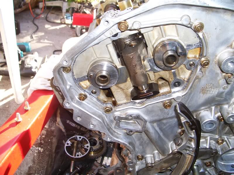
Now you can start putting on the timing components. Put on the timing sprockets, and the secondary chains. Install the water pump. Line up the notches on the sprockets with the marks on the chain. Tighten the exhaust cam sprocket to 85 ft-lbs. It has to look exactly like this, on both sides:
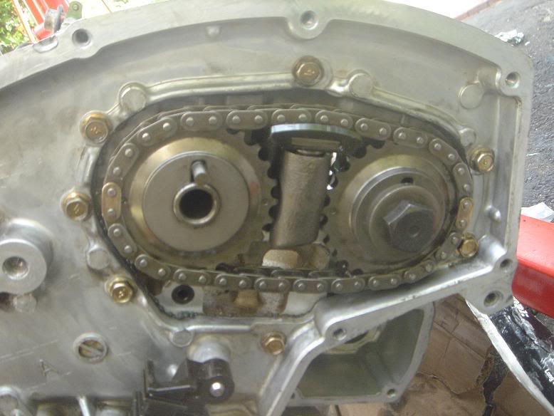
Next, put the main timing chain sprocket and crank sprocket on, tighten the main bolts to 85 ft-lbs, and install the chain, making sure the marks on the sprockets and crank line up with the marks on the chain. There are two similarly colored chains, and one “oddball”. The oddball belongs right at the mark on the crank sprocket. There’s an indentation where it belongs, and there are arrows on the main sprockets where the other links belong. This is also outlined in the FSM. If not everything lines up, turn the cam VERY carefully and line it up. Put on the chain guides and tensioner. This is what it should look like:

Now that we have our timing set, double and triple check. You might want to move the whole assembly to see that it all moves and doesn’t skip a tooth, it’ pretty easy to mess up in this stage.
Install the outer timing cover, making sure to put a clean bead of sealant on it, and getting rid of any old sealant.
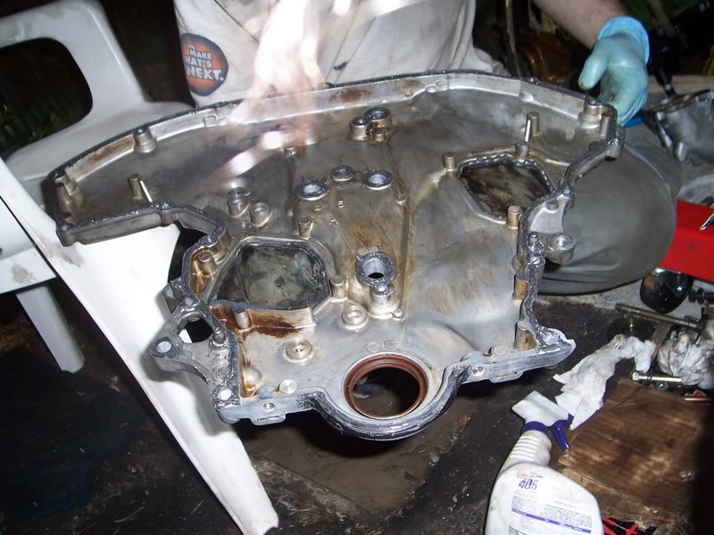
Make sure the two dowels go in at exactly the same time, and install all the bolts. I personally didn’t worry about the order of the bolts, I just made sure they were tightened down to 10-15ft-lbs. Be very careful, they can crack easily.
Now bolt up the engine mount, and crank pulley.
Here’s the finished product,
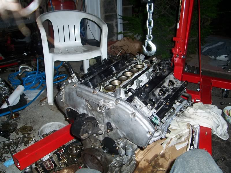
Now it’s starting to look like an engine. Next we’re going to install everything else that we need from the 3.0, which are the headers (6 14mm nuts), the AC compressor, PS pump, belt tensioner, both belts, alternator, thermostat, and coolant tube on the right side of the engine (the one that houses the Engine Coolant Temperature Sensor). You need this coolant tube because the 3.5 is missing one sensor the 3.0 has, not to mention the various vacuum lines that run on the top of the coolant tube. This tube can be taken off with 4 12mm bolts. The injector sub-harness has to swapped (in the rear of the engine) and the crank REF sensor has to be installed on the bottom of the crank pulley. Connect the oil pressure sender and run the harness so it doesn’t touch the headers, or the power steering pump.
Cut off the 3.0 injector plugs on the harness and make sure you have a lot of wire on the harness. Now cut the 3.5 injector plugs off, and splice them into the harness. If you’re confused about the power and ground, the red one is always the power. You’re only going to do half of the injectors now, as we’ll do the rest when the engine is in the car.
Now you’re ready to install the flywheel and clutch. Make sure the timing ring is on the flywheel (secondary ring behind the flywheel), or else the car won’t start. Take the flywheel off the old VQ30 by first removing the clutch (9-12mm bolts), then removing the 14mm bolts in the middle, and easing out the flywheel. It’s a bit stubborn, but try and pry it on each side and pull gently. Toss the old clutch, it might as well be a Frisbee now.
You can have the flywheel resurfaced, but mine was in good shape, so I just went over it with some 80grit sandpaper and simple green to get the dirt off. Works like a charm. Install the flywheel on the VQ35, making sure not to get grease on the contact area. Then install the clutch, torquing the 12mm bolts to 35ft-lbs.
Now that that’s installed, we can lift the engine from the same mounting points as before, and install the lower oil pan. As with any old sealant, scrape it off, and make sure the surface is clean and smooth before applying the new gasket. Carefully place the oil pan on the engine, and tighten all the bolts.
Now the engine’s ready to go into the car.
Again, I’ll save some space and write that it’s the reverse of removal, and through experience, I’ve found it’s a bit easier to put the tranny on the engine outside the car, then lower them into the engine bay, both at once.
You can start putting the harness back on, and now you can wire the other half of the injector harness. The coil packs plug right in, just as they should, just make sure not to overextend the wires for the rear coils, there’s not a lot of room to work with. After you run those wires, you can put on the intake manifold.
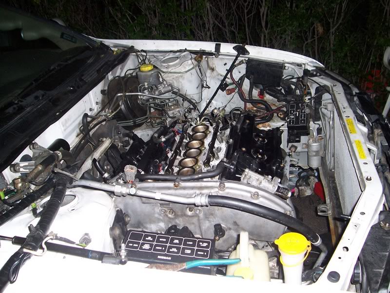
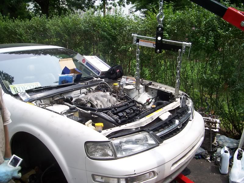
Reinstall radiator, hoses, coolant lines, power steering lines, y-pipe, crossmember, axles, and shifter linkages. Fill The radiator, engine, power steering reservoir and tranny with their respective fluids.
ALMOST THERE!!!!!
We have two more things to deal with: The throttle body and fuel.
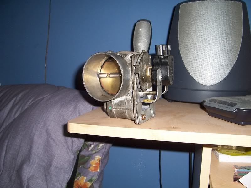
Throttle body: The 3.5 uses a drive-by-wire system that the 4th gen simply doesn’t have, so you’re going to have to make your own bracket to house the throttle position sensor, and throttle cable. First you break the housing of the drive-by-wire system, then you take out EVERYTHING. This should leave you with a rod that you can mount your 3.0 throttle wire bracket to. There’s a little piece of metal that you must use, in conjunction with a lock nut to keep it all in place. I made a bracket out of metal, secured it with bolts, and put the throttle position sensor on that. The hardest part is making the throttle position sensor turn cleanly with the throttle body. You also have to make a bracket to hold the throttle cable in place. Any piece of scrap metal cut to shape will fit. Use your imagination.
This is how mine came out:
Fuel:
The Vq35 uses a returnless fuel system, and the 4th gen has a return system. The solution?
Get a tee and adjustable fuel pressure regulator ($25 shipped on eBay), and run the fuel lines like this:
…..Adjustable FPR set to 52psi —-return line………| Feed—-fuel filter—–tee —– fuel rail
Now make sure you have everything connected, wired up, and sealed.
*FINAL CHECKS*
You can use your stock air box, with a coupler or two. Connect all vacuum lines, including PCV and brake booster to the rear of the intake manifold. Connect the starter, and all grounds.
Connect the battery terminals, and start the car. It should be a little rough starting in the beginning, but it should run pretty well. Let all the carbon and grime burn off, and make sure to give it a tune up after 1000 miles.
Notice I didn’t include a guide on how to hook up the variable intake manifold. I did so for a reason – I didn’t use it. I modified my intake manifold (dubbed V-Spec), so I have more air volume at all rpms. If you want this done, please inquire.
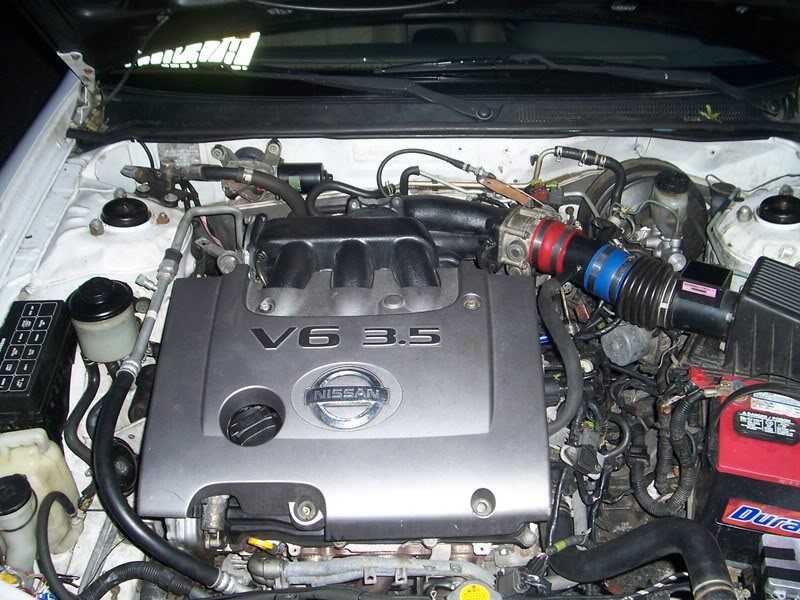
Afterthoughts
Any ECU will work with this swap, I’m running a 1998 auto ECU (stock), but I do have some Check Engine lights. Personally, they don’t bother me, but a bit more work and planning has to go into the swap if you don’t want check engine lights. I have codes for the IACV (not connected), and EVAP system (not connected)
You cannot use a strut bar with the 3.5, the manifold sits too high. I’m currently working a way around that, however.
How long does this swap take?
Mine took about 4 days, doing everything carefully, but it can be done over a long weekend. There was a point where I had both engines taken apart, where it was a bit overwhelming, and I thought “I’m not going to have a car to drive next week”, but you get over it when you’re working at a steady pace.
Is it worth it?
In one word: Definitely.
Thanks:

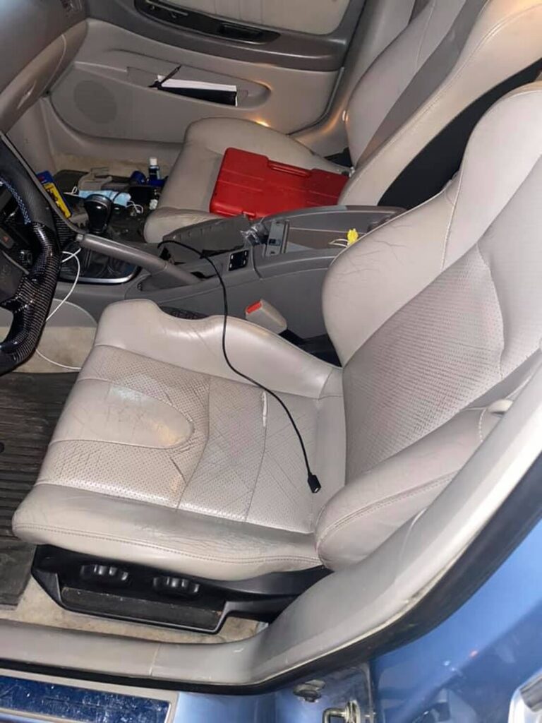
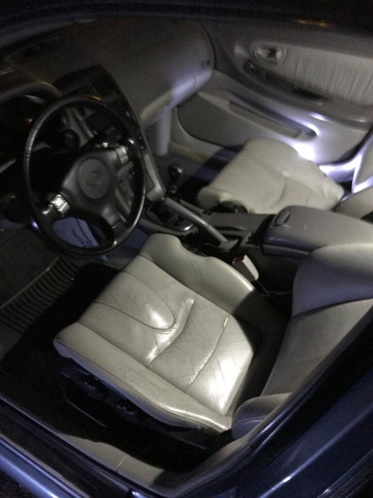
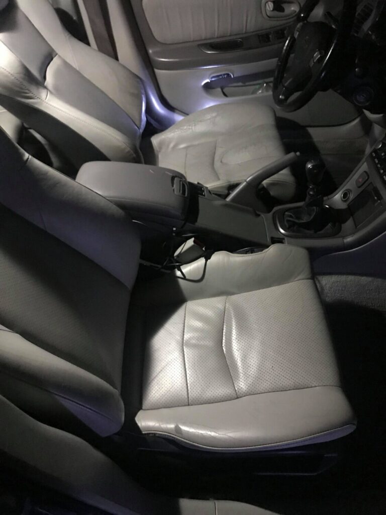
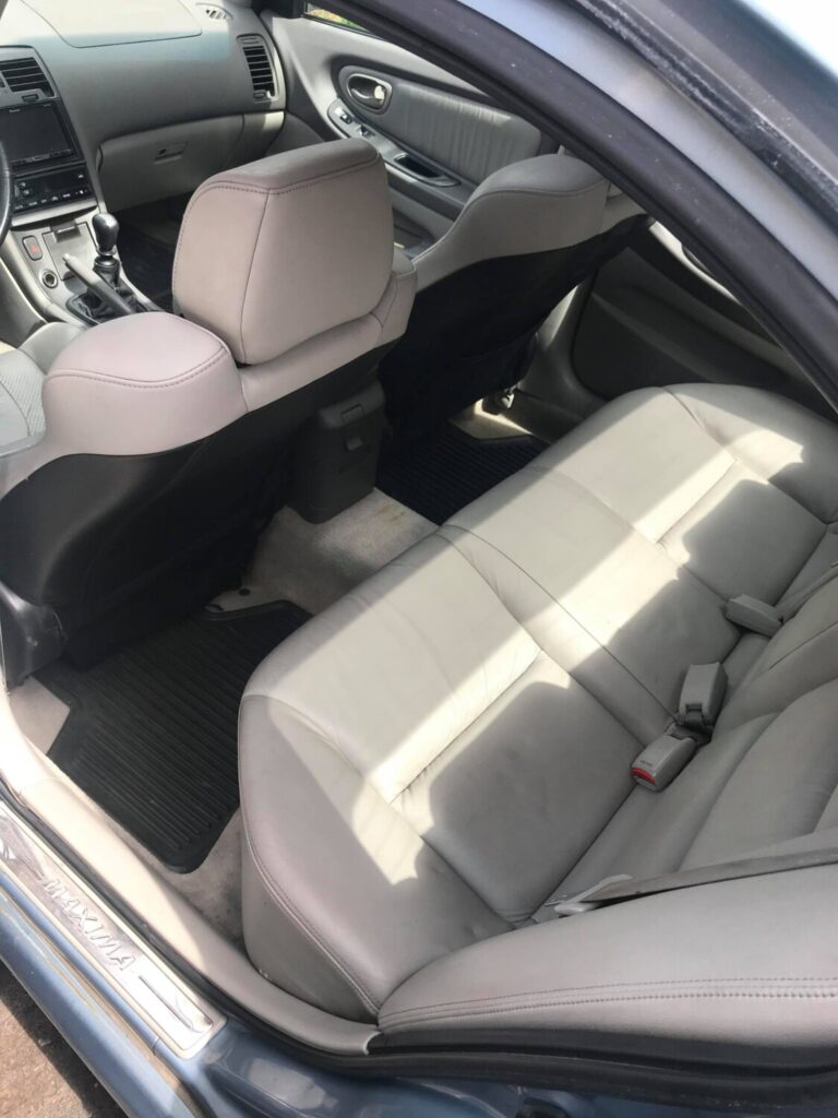
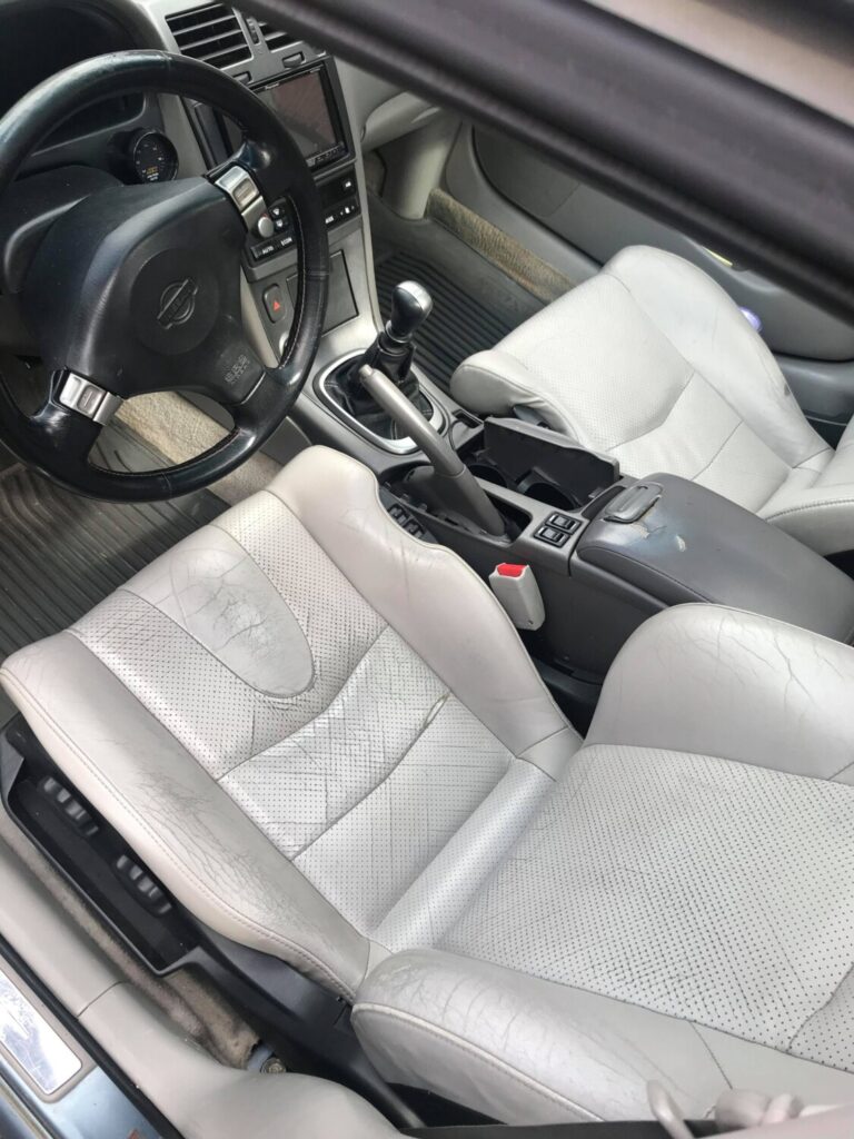
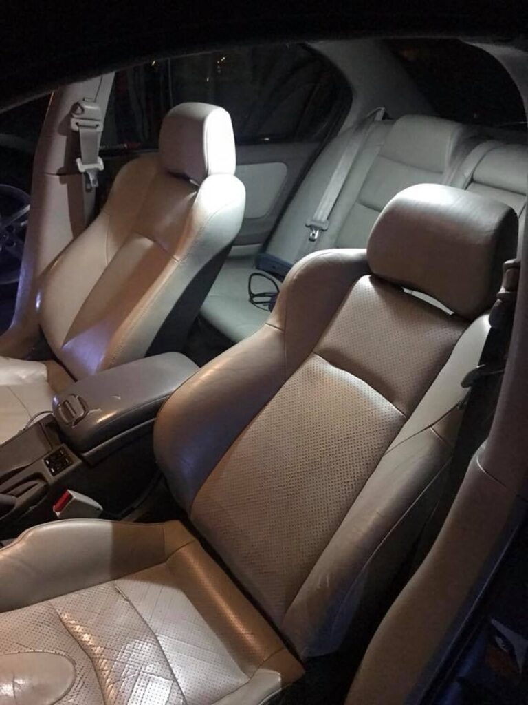
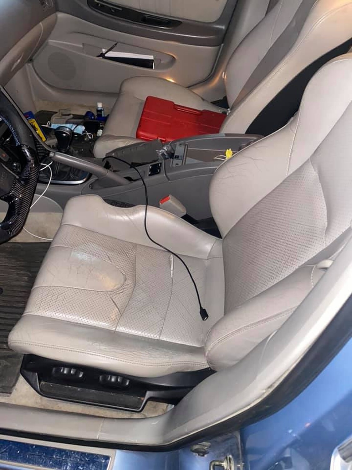
The track width between the 350z and Maxima was the exact same and was key to making this swap work. Also viable, using a seat from a B15 Sentra (00-06) – as these are a direct swap with 5/5.5 Max seats. Also, this guide is only if you have 2 manual front seat rails. All stock Maxima ’02/03 driver seats are power only but some ’00/01 Maxima driver seats are manual…I harvested a manual driver seat from a junkyard ’02 Sentra for the rail.
I studied the tracks for a while to see viable options and this resulted in my final procedure. By changing out the seat brackets my way, I lost about half an inch in sliding backward…not an issue for me and I’m 6’…but I also gained full functionality of the 350z seats. I also chose to go with the manual versions, so if you’re in there looking for wiring help – sorry but no, lighter is better for me.
The main tools you will need:
Start with the Z seats since they’re most likely not in the car when you’re starting. The process below is the same with the Z and Maxima seats EXCEPT the Z seats have a bracket alongside the inner edge that needs to be cut off. As seen here:
You’ll want to remove the seat cushions and back to make it easier…and to keep the fabric from getting possibly messed up. There are 4 bolts on the seat bottoms near the corners that need to be removed. The seatback has 2 bolts on either side that need to be removed. Once those are out the back comes off easily.
Now, the seats roll on a couple of rolling brackets, one in the front and one halfway down. The object of the drilling is to remove any kind of resistance the factory created in the rails to prevent the seats from rolling too far forward/backward.
There is a single aluminum welded bolt that can be drilled through on both rails in the front. These are present on the Maxima and the Z seats.
Once that is out of the way, you’ll see some ‘dimples’ in the rails. I believe my other set of rails had 6 total but these Maxima rails show 4 total. Drill those out.
Again, the main objective is to remove anything that will keep the rolling brackets from rolling too far forward. Once you have the front welded bolt and dimples out, you may notice it takes a little bit of force to get the rails to slide the rest of the way off. I found that the dimples actually still had a little bit of a ‘bump’ that needed to be removed.
The Z bracket on the side will still need to be removed before you can get to the dimples that it covers. If you don’t have a grinder I guess a Dremel would work, just very time-consuming. You could also take it to a muffler shop and ask to have someone safely cut the bracket off. Remember you still need the rails.
Once you’ve drilled all that out, the rails should slide off. Keep in mind the rolling brackets will come off. They aren’t hard at all to slide back on, you’ll see what I’m talking about when you’re there. To finish things off, you’ll need to transfer the seat belt lock from the Maxima seat to the Z seat. Just a simple bolt holds it on. (The Z seat belt lock doesn’t fit the Maxima seat belt)
Anyway, that’s pretty much it. When you have the Maxima rails onto the 350z tracks then it’s the 4 bolts to put the cushion back on and 4 bolts for the seatback. One last couple of notes, I lost the ability to raise/lower the driver seat…I don’t really care but some people might. Also, you CANNOT use the Z seat trim on the bottom NOR the Maxima seat trim. I’m not aesthetic so IDGAF what it looked like, the seats are comfortable as he11 to me.
Additional Note:
If you have an ’02/03 Maxima driver seat then you’ll see its power. I ended up using a Sentra manual driver’s seat so I can’t help with that. Some ’00/01 Maximas came stock with manual seats as well, thanks MONTE 01&97 SE!. The power seat has a different setup, with a bolt that holds the rail on the motor ‘screw’ device on either side (see next pic). I’m sure there’s a way around it, I just didn’t deal with it. A driver-side manual Sentra rail from the junkyard cost me a whopping $30 so it was a non-issue to me.

Applications
Tune On The Go is proud to present phenolic its 2pc thermal intake spacers. These spacers are made from 3/8 thick high-grade phenolic. The spacers will isolate the throttle body from the manifold and also the manifold from the block.
With the isolated areas spaced off this way the manifold will run about 23 degrees cooler thus creating colder, denser, heavier air into the chamber
Sold as a complete kit which includes:
Community Member Credit: Eddy
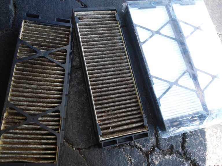
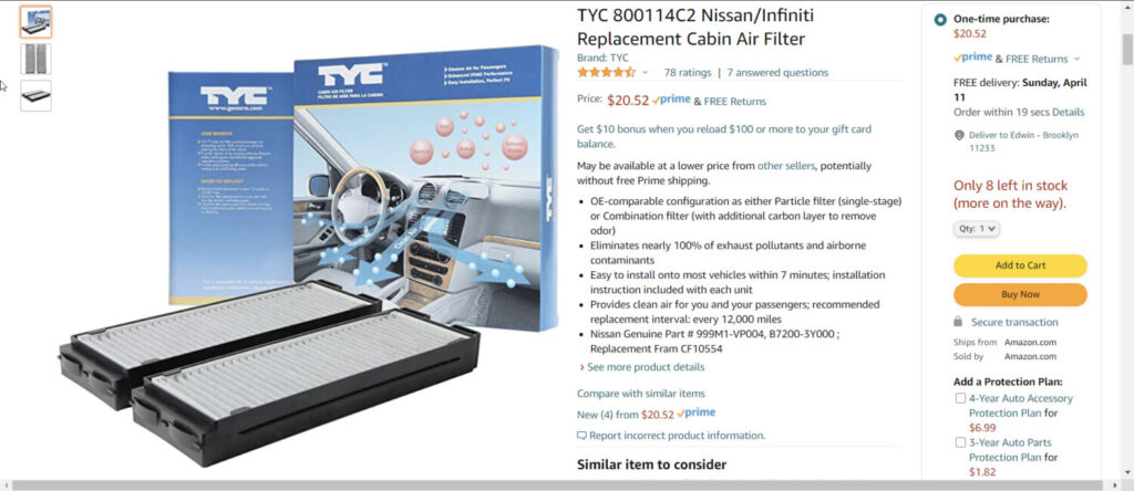
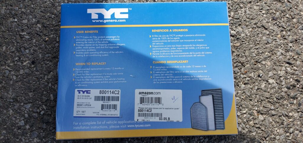
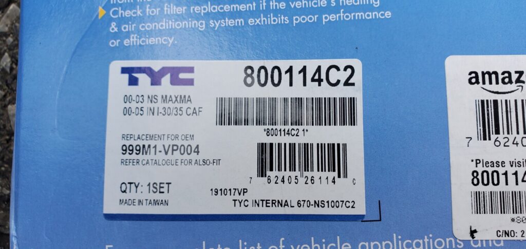
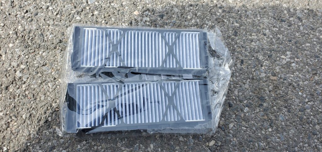
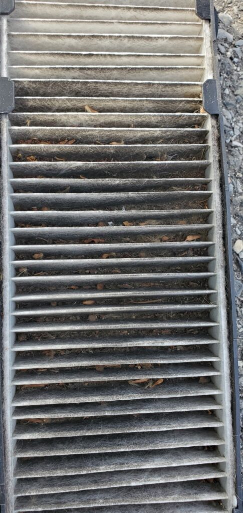
I was changing the blower motor on my car and decided to change the cabin filter. When I took out the cabin filter I noticed it was two pieces. I found TYC 800114C2 on Amazon for $20.00. It had solid good reviews so I went with this one. Looks like the OEM one is 1-piece but I decided to stick with the 2-piece I already had.
Why change it?
Description: TYC 800114C2 Nissan/Infiniti Replacement Cabin Air Filter
Price: $20.00 Shipped
Order Link: https://www.amazon.com/dp/B002E59QCM/ref=cm_sw_em_r_mt_dp_B4906A6DSCME3A0N7Z39?_encoding=UTF8&psc=1
Reference Part Numbers:
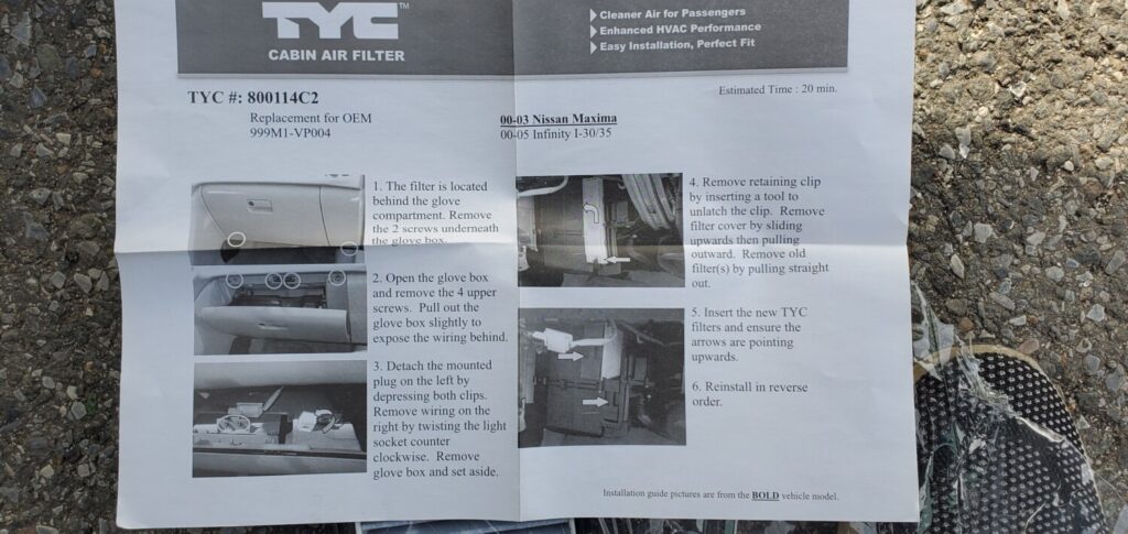
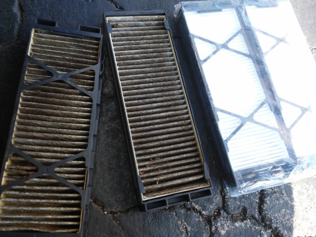
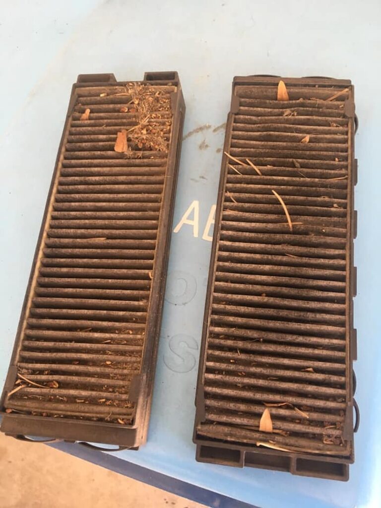
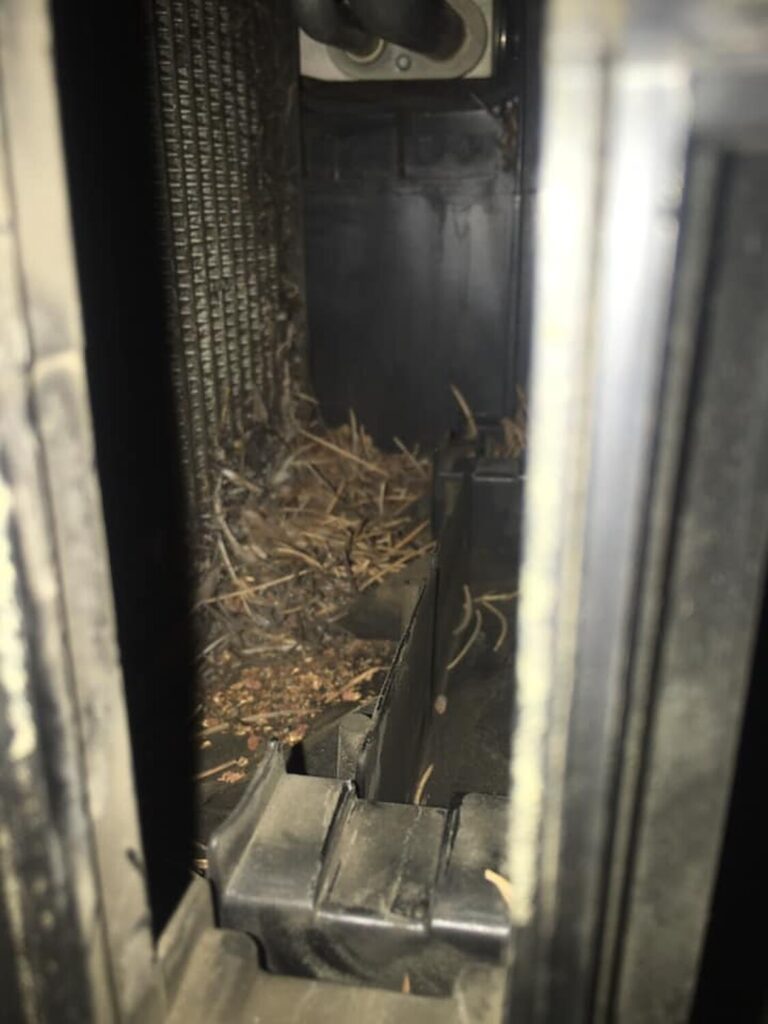
Make sure you use a vacuum to clean the inside of where the filter goes.
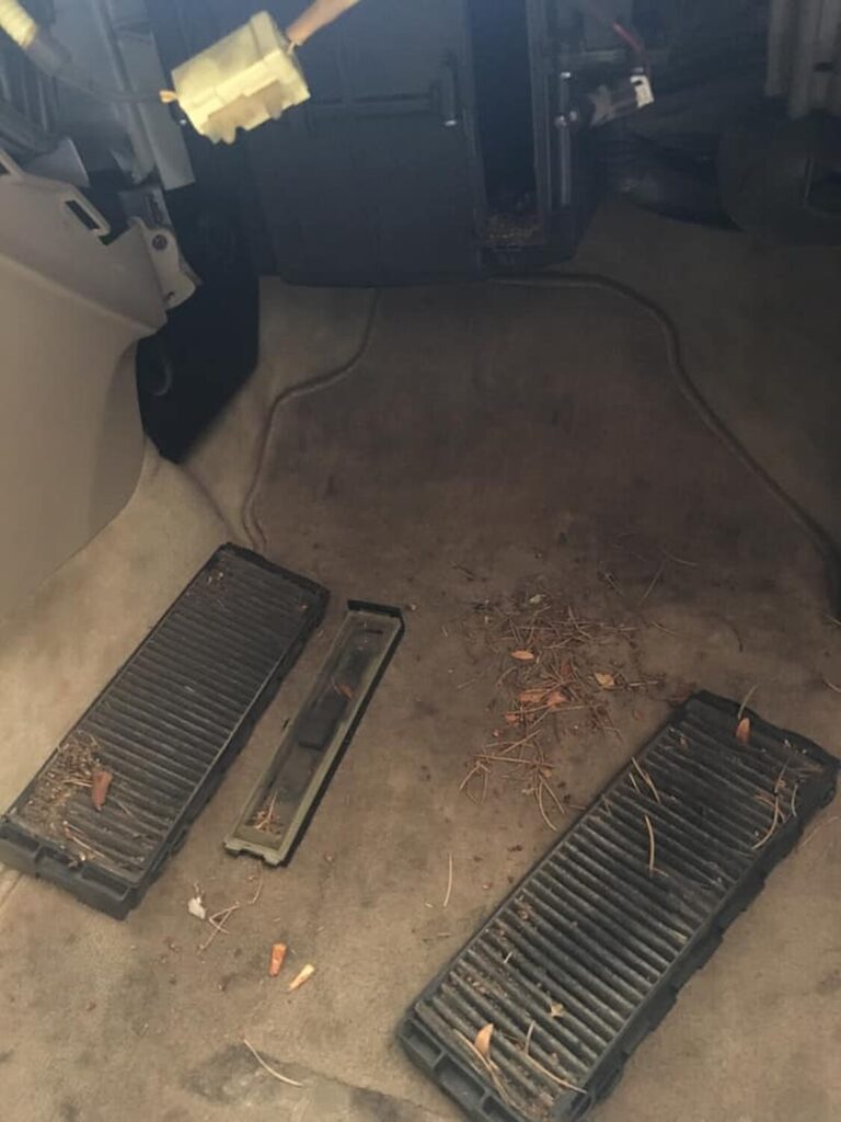
Community Member Credit: carzoneautorepair
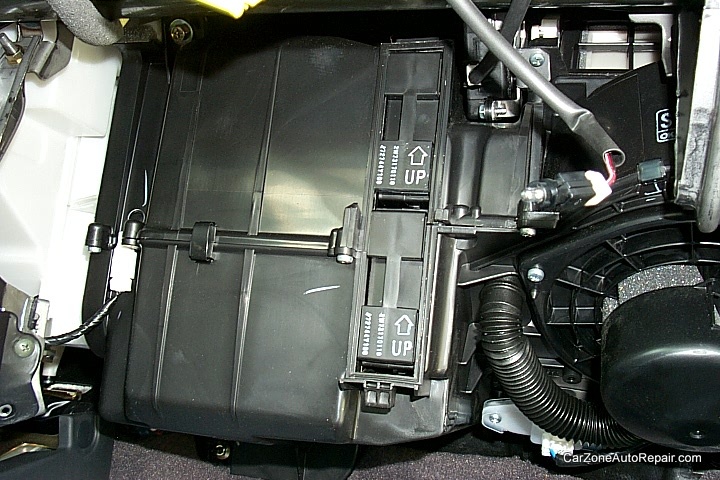
These are the Nissan-Supplied instructions for the In-Cabin Microfilter. They are somewhat generic and were not 100% accurate to my car. The only difference was that my car did not have the “Glove Box Finisher”. Besides that, everything else was correct. Perhaps the Glove Box Finisher was eliminated in later 5th-Gen Maximas?
I bought my filter at a Nissan Dealership. The cost for one of these babies is $58.74!!! Cheaper deals can probably be had on the Internet.
Nissan recommends changing this filter approximately once per year. This procedure is not listed in the owner’s manual, as Nissan prefers this operation be dealer-installed. With only a Philips screwdriver, if you are the least bit competent you can do this job yourself and save money. The filter alone is expensive enough!!

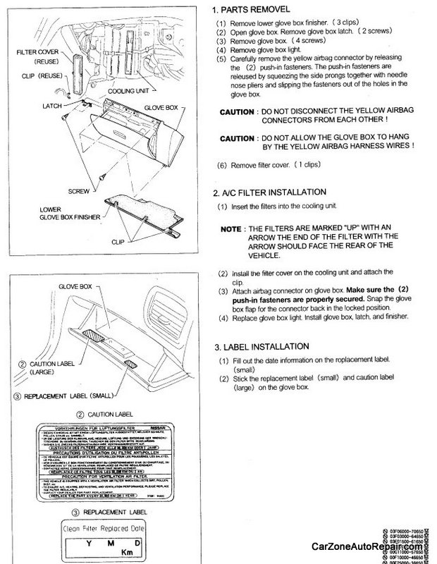
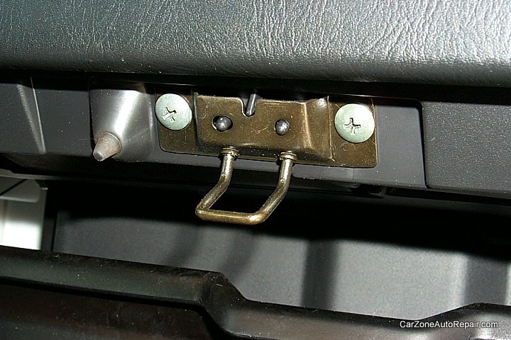
1. Start by removing the glove box latch. 2 screws and it’s out.
2. Next, remove the 4 screws holding the glove box in place. There are 2 at the top and 2 at the bottom. You will have to disconnect the glove box light and the airbag connector. Both come off easily, and the entire glove box can be removed.

3. Once the glove box is out, the next step is to pop off the metal clip holding the white filter cover in place.

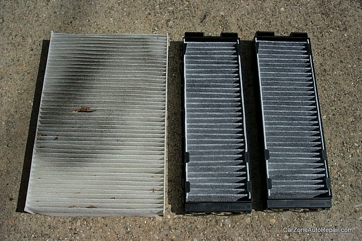
4. Now the filter can be slid out. Apparently, the microfilter put in at the factory is a single piece, and does not look like the factory replacement filters you will put back in. In fact, the replacement filters look much nicer (higher quality). This picture shows the empty hole where the old filter was.

5.This side-by-side shows the stock filter removed on the left, and the replacement filters on the right. I was quite amazed at how dirty this filter got. The replacement filters come in two pieces and have plastic holders that enable them to slide into place more easily than the original filter.
My filter had all sorts of black dirt, crud, and leaf pieces in it!!! And I keep this car garaged, and never drive it in the rain (if I can help it).

6. The easiest way to get the new filters in is to put one in at the bottom, then once it is in, slide it up into the top position, since it is difficult to get the proper angle to put the top one indirectly.

7. Here is the completed filter installation, with both filters securely in place. Replace the white filter cover, glove box, reconnect the light and airbag connectors, and this installation is complete. Ahhhh, fresh air to breathe once again.