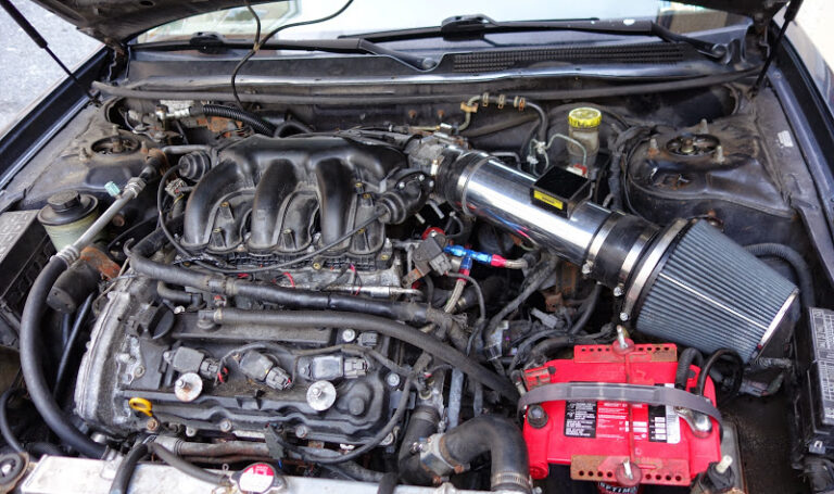
This isn’t a one time wonder either. It first ran 10.98 then the very next run backed it up with the 10.85. The record was obtained on October 5th, 2008 at Toronto Motorsports Park, Ontario, Canada driven by JIME himself.
Yes that’s right, it runs 10’s… And gets groceries too.
1/4 Performance Records:
Nitrous
All Motor
95 Maxima GXE VQ35:
10.85 @ 125.55 MPH
12.3 @ 111 MPH
Notable Racing Accomplishments:
2008 Summit 3rd place
2008 CSCS Street Wars Champion
2008 CSCS Bracket Points Champion
Mod List:
Engine, Trans & Exhaust:
2002 VQ35 3.5 Engine Swap with A33B ECU
Stock Bottom-End
SSIM Intake Manifold and Drive-by-wire Throttle Body
Ok guys after spending a lot of time and money last year I ended up using an automatic shifter dubbed shift-fast for my automatic transmission.. It is just some relays connected to a RPM switch (Emanage\UTEC\MSD). It works fine, it allows me to shift at any RPM I desire automatically which is great for the track. However it doesn’t control the converter lockup and I have to use the exact same shift RPM for each gear. The trans takes longer to shift from 2-3 than from 1-2 so the RPM is higher for the 2-3 shift, not exactly what I want. I was trying to come up with another way while watching the snow fall and although using 2 window switches would solve part of the problem its just more wiring and relays. Grey99 has also spent a lot of time working on the automatic shift-fast and has his own version working quite well.
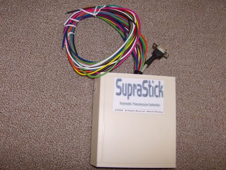
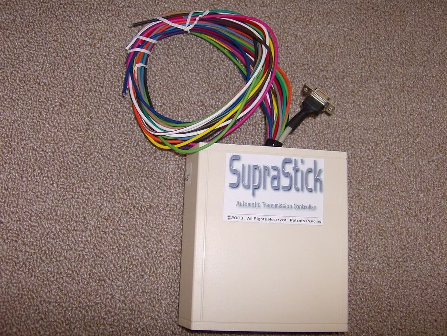
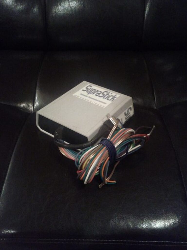
I decided to do some searching to see if anyone else had come up with an easier solution. After a few hours of searching I ran across a device made for the automatic Supra that does it all. Suprastick V4. Individual shift points for each gear, torque converter control for each gear, 2 maps (one for race one for normal), manual shift mode using paddles or switches, shift light, automatic protection from downshifting. It is a complete standalone TCU programmable via a PC. I have been in contact with the President and Chief Design Engineer Garrett Rowe who assures me he can easily change the code so it will work with the Maxima shift pattern.
The Suprastick manual can be downloaded here: SSv4.6 – Manual
I checked the G20 FSM and your trans in the same number of solenoids and same shift pattern as the Maxima/Altima so this will work.
Ok here goes. Does the SupraStick work? Yes, exactly as advertised. It comes packaged like this.
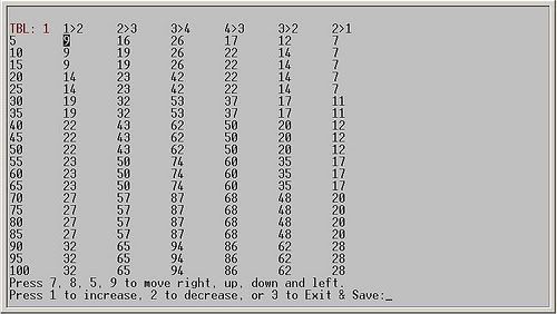
There are a number of programing screens to set it up but this is the most important one. There are 2 maps for auto shifting one for track and one for street or whatever. Just insert the speed you want it to shift at with the applicable throttle opening and bingo it does it. I have 2 switches one to select map 1 or 2 and another to select manual or auto shifting. I use the cruise control buttons for the manual up down shifts and it works great. One of the options is to set an RPM limit for downshifts, whatever you set this RPM for the trans will not downshift if it is exceeded to save your trans.
Does it work at the track? I waited until today to post this. There were around 24 cars in the field and I managed to win it all. Not too bad for an old guy that was paralyzed from the neck down 8 months ago. Youth and skill can be overcome by old age and treachery every time.
This is a pic of the display which is available for approx $35 to show mode, gear, throttle opening, speed and rpm.
This mod forces the transmission to shift at FULL Line Pressure at all times the switch is on. A WOT (Wide Open Throttle) switch is best suited for this purpose because the part throttle shifts are extremely harsh and could damage the transmission.
The drop resistor mod disconnects the dropping resistor in the transmission control circuit. This forces the transmission to run a maximum line pressure. This makes the shifts VERY hard. Even an otherwise stock car will chirp the tires on the 1-2 shift with this mod.
The downside is that part-throttle shifts are very jerky. The solution is to wire a Wide Open Throttle (WOT) switch that disconnects the resistor only at full throttle.
Reference Info:
The line pressure is varied according to throttle opening, RPM etc so that the more power you put down the more pressure is produced so that theoretically the shift time remains the same.
The more HP you put out the slower the trans will shift if you don’t increase the line pressure, so they have designed it to be suitable for 95% of the driving public.
What I am trying to do is have maximum line pressure at WOT ONLY, I like the way it shifts under normal operation, thats why I don’t have a VB mod. Maximum line pressure gives the fastest shift possible and saves the clutches from burning unecessarily. However I don’t want maximum line pressure at part throttle as the shifts are very jerky because the engine is only putting out very little HP.
The stock design does not put out maximum line pressure at WOT and the Drop Resistor Mod does.”
Installation Pics
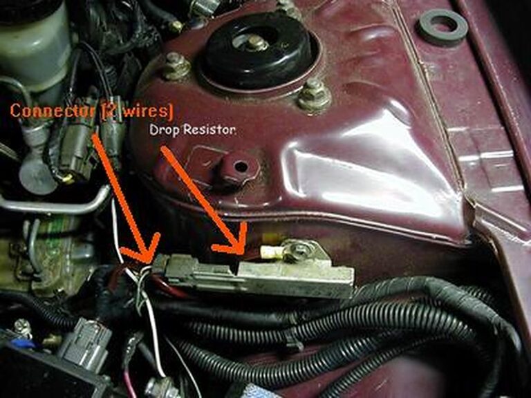
Ok here is where the drop resistor is located. Front side of the drivers side strut tower.
There is a connector with two wires attached to the resistor. The electrical drawing of the drop resistor looks like this. You must cut one of the wires, doesn’t matter which one but cut it at least 2 or 3 inches from the connector so you have room to strip and connect to it.
Strip a small section on either end of the wire you just cut and attach a wire to each end by soldering or use a connector. Run the two wires to a switch. Either a WOT micro switch (preferably) as per the picture or a manual switch.
I have a small L bracket I made that attaches it to the intake manifold bolt closest to the throttle body.
Keep adjusting the switch position until the throttle hits it just before or when it hits the WOT position. It is imperative that this switch be a Normally Closed (NC) switch so the circuit is always made until you hit WOT at which point it opens and effectively disconnects the drop resistor from the circuit.
You can do the same thing by running the two wires to the cabin and hooking to manual switch (5 amp rating or higher) but I much prefer the WOT switch because you never have to worry about turning it on or off. You have enough to think about when racing without another stupid switch to turn on and off.
The micro switch I use is rated at 10 amps and I got it from an appliance shop where it is used in a microwave.
Most switches of this type are Normally Open (NO) and this will NOT work.
The Suprastick manual can be downloaded here: SSv4.6 – Manual
Tools Needed
Wire stripper
Wire taps
Wire quick connectors (slide or bullet style)
Soldering iron
A lot of wires
Additional Parts Needed:
DB9 male to DB9 male serial cable (for LCD screen)
Null modem adapter (for LCD screen)
USB to serial cable
16×2 LCD screen with serial port (optional but recommended)
Shift light (optional)
Two SPST toggle switches
Before you begin, disconnect the neg terminal of the battery.
Installation Steps
Step 1:
Remove shifter trim, ash tray, and the whole middle piece (one w/ the cupholder and armrest) for easier access to the TCM.
Step 2:
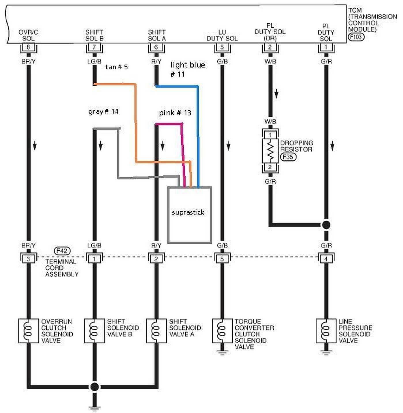
Locate the TCM, should be directly in front of you, you can’t miss it. looks like the ECU. remove clear plastic cover. here you will need to identify just 2 wires, one for solenoid A and other for solenoid B. these are the solenoids that controls your gear shifting.
Step 3:
Intercept wires 6 and 7 like so:
*Optional* If you want to let the suprastick control the TC lockup feature, you will have to cut wire #5 on the TCM and connect it to wire #15 on the suprastick. Then you will have to find an adequate brake signal source to tap into.
Step 4:
Finish wiring all the other wires
Suprastick:
wire 1: wire to ground source
wire 2: wire to a SPST switch, other end to +12V source
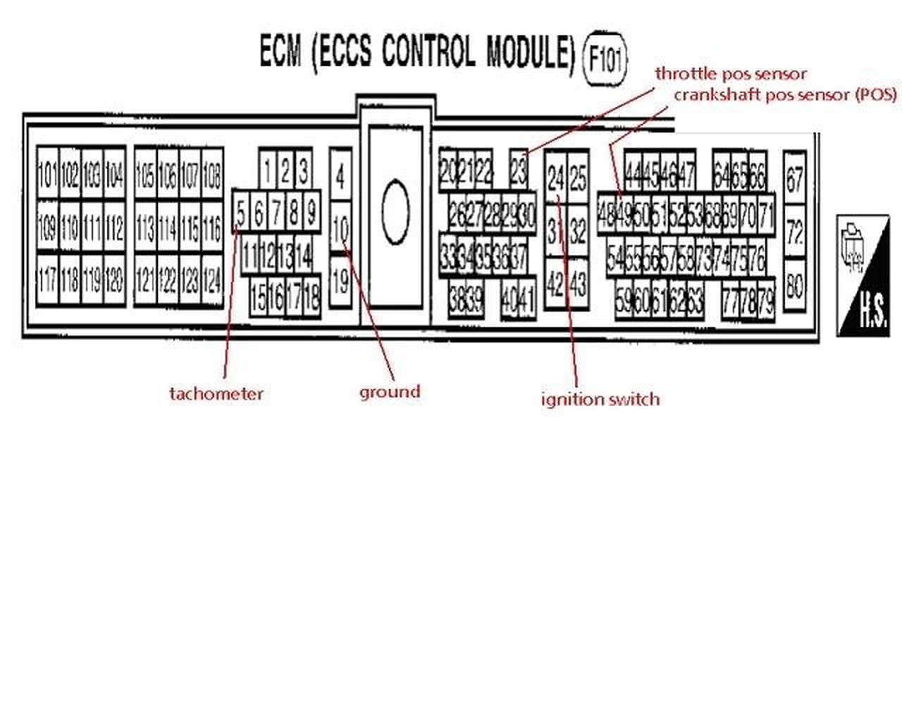
wire 3: tap into pin 24 on ecu
wire 4: refer to step 3
wire 5: refer to step 3
wire 8: Tap into pin#28 on the middle harness behind the gauge cluster.
wire 9: tap into pin 23 on ecu
wire 10: tap into pin #1 on the ASCD, located above the gas pedal (EL 151 of FSM)
wire 11: tap into pin 5 on ecu
wire 12: optional, refer to step 3
wire 13: refer to step 3
wire 14: refer to step 3
wire 15: optional, refer to step 3
wire 16: optional
wire 17: tap into pin #2 on the ASCD, located above the gas pedal (EL 151 of FSM)
wire 18: Optional
wire 19: Optional
wire 20: wire to a SPST switch, other end to a +12V source
For Wires 18 and 19, again this is optional. this is for the drop resistor, to run maximum pressure for the tranny line. i have mine connected to another toggle switch but if you want the suprastick to control it, just run it inline with the two wires on the drop resistor.
Step 5:
* Now for the programming. I’m not going to go too much into detail for this part b/c that’s what the manual is for. But there are a couple things that i need to mention that will save you time and headaches.
* For the initial setup, when your setting up your hyperterminal, select the correct COM port and follow all the settings. One thing you want to keep an eye on is the “hardware flow control” setting. try setting the flow control to hardware first and see if the hyperterminal screen corresponds when you push 1. if it doesn’t, disconnect, go back into the flow control setting and turn hardware flow to NONE. Now it should work.
* Couple things for the Vehicle settings. One advice is, keep the speed sensor teeth to 20 and just adjust the rear end ratio until the spd display matches the speed on the gauge cluster. Best to do this w/ 2 people, one driving at a constant speed of say 20 mph, and the other adjusting the rear end ratio.
* Also, remember to correctly adjust the shift pattern under the shift solenoid setup. by default its for the supra.
* for the automapping, the stock ecu defines your driving style, and not the other way around. The SSv4 will learn the stock ecu shift points if you have the stock ecu hooked up to it. Just drive the car once through the largest throttle range possible for as large a speed range possible and you are done. It is usually just quicker to tweak the base map provided, however.
That should do it. if anyone is interested in doing this and have any questions, please don’t hesitate to ask.
First off, I just want to say that I got this idea from Jime. He purchased a 300amp battery jump box and used the battery out of it for his car. It weighed 6 lbs. I believe he had problems with it starting. So he purchased a 400amp battery jump box with a 12lb battery and has been using that ever since without issues. Jime, please correct me if I say anything incorrect. Thanks.
So I found that Harbor Freight had the best deal on a Battery Jump Box. So I purchased a couple of them. One to keep in the trunk of my car and one to use the battery out of.
The jump box I used was a 650amp one found here (Item #40615):
It’s the largest one they had. But before I ripped into this one, I looked at the manual and simply decided to order the replacement battery direct from Harbor Freight by calling their customer support at 1-800-444-3353. The battery cost $32.70. I order another battery for my HF drill, so that increased shipping costs to $7.99 instead of approximately $6.00 I think. The item number printed on my receipt for the battery is 26307. But you shouldn’t need that. Just give them the item number for the Jump Box and tell them you want the replacement battery.
The battery weighs 14lbs.
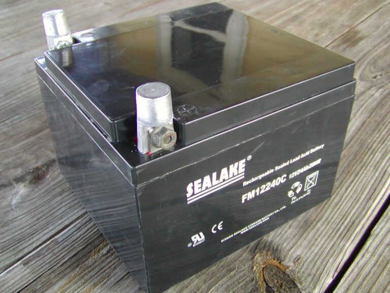
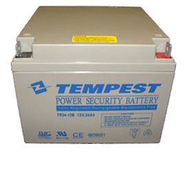
Here is what the battery looks like:
First I had to install “flag to post” adapters. I ordered them through my local Napa store (Part # NW 728219) for $6.29. They come in a pair and were cheaper than ordering them online from a battery supply store.
I had to slightly drill out the flag terminals on the battery with a step drill bit in order to use some spare M6 bolts I had laying around.
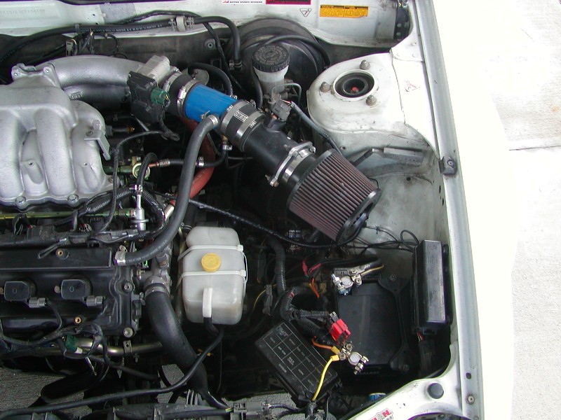
Next, I had to figure out a way to mount it in my 3rd gen. I really wanted to get rid of the battery tray as well for further weight reduction. But this posed several other problems. One being, the coolant tank attached to one of the battery tie down bolts. Plus, a couple relay boxes attach to the battery tray.
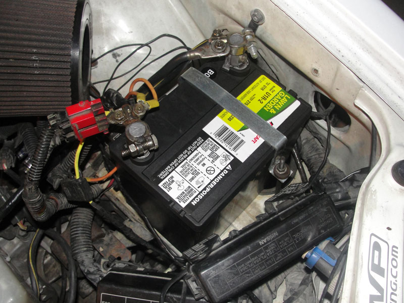
Out with the old battery. It weighed in at 40lbs and the tray is 3lbs.
I zip tied the coolant tank to the coolant tube on the VQ35. I know it’s ugly, but it’s ok. I’m only worried about performance here.
I put a fresh coat of paint on my OEM tie down. I found two bolt holes already in my frame that I was able to use. So I had these long M6 bolts laying around that I was able to use.
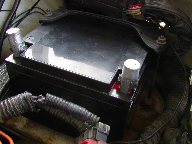
Here is what the battery looks like installed. I put some rubber bands on the bolts to prevent the bolts from ever dropping through the bolt holes. The bolt holes in my frame were threaded for M8 bolts and I didn’t have any M8 bolts that were long enough or I would have used those.
I was able to zip tie the relay boxes securely.
I installed a cheap Harbor Freight multimeter inside my car so I can always keep an eye on battery voltage. So far, this battery cranks my car up just fine. I have noticed that sometimes, the engine has to turn over one more time to get it to fire up. But this is not a concern. I believe this may be due to the engine turning over a tad slower than before. My old battery was the largest and highest CCA Duralast battery that Auto Zone had to offer. But it’s served it’s life as I bought it back in 2003.
Well that’s it. A weight reduction of 29lbs for under $40! I hope this helps somebody in the future. Thanks Jim for the idea!
I went to Advance Auto Parts today and bought a battery for $31.99. It has 230CCA and 275CA and weighs 15lbs. It works just fine in the summer. So I’m happy. I just had to make a new tie down since it sits higher than the jump box battery. Car starts with plenty of power.
At one point on the Maxima message boards in late 1999 there was a lot of talk about increasing airflow through the Maxima intake by removing the screen from the Mass Airflow (MAF) Sensor. The screen is not a secondary filter as one might suspect. Its purpose is to “straighten” airflow going into the throttle body. The theory is that removing the screen will allow increased airflow and thus, more horsepower. Being a logically thinking person, the science behind the theory sounded good to me, and I am willing to give anything a try that sounds reasonable so…. I removed the screen from the MAF sensor (this process is irreversible!!) and ran with this mod for almost a full year. While I did not notice any harmful effects from removing the screen, I can say for certain that this mod does not increase horsepower in the slightest, and might possibly even screw up the MAF readings. Read on.
For comparison purposes, here are two Mass Airflow Sensors from a 4th-Generation Maxima. The one on the right has had the screen removed for (presumably) higher airflow. The one on the left has the screen intact.
The way the MAF sensor works is that it measures the airflow through a very small opening in the center of the sensor and sends a variable voltage out its electrical connector to the ECU. The ECU is programmed with the diameter of the sensor and computes the total airflow into the throttle body based on the flow through the center section. The reason for the screen is to ensure that the airflow going into the center portion of the sensor is straight and smooth so that the ECU’s computation will be accurate. If the flow is not smooth then the ECU computation of total flow through the barrel will be off. In my opinion, removing the screen will quite possibly allow a more turbulent airflow through the MAF sensor than without the screen.
In spite of my theories as to why the screen is there and what (I believe) could happen if it is removed, I still noticed no detrimental effects from removing the screen. However, since there was also no tangible benefit from this mod I chose to re-purchase a new MAF sensor and re-install it with the screen in place.
What a relief, after weeks of dealing with stalling max, she purrs like a kitten again. The fix took 10 min, by simply running extra grounding wire from MAF to the chassis. All stalling when coming to stop , shaking at idle, stalling in reverse and running rich is now gone !!!
If you experience stalling issues (with no CEL) and have tried all the basic troubleshooting like: clean TB, IACV, ECTS, plugs, filters, coils etc and nothing seemed to help, you need to check your MAF sensor ground.
Simply back probe the black wire on MAF connector with positive lead of the voltmeter and negative lead pressed to one of the ground connections on the engine block.
The voltage at idle should be less than 9mv (0.009v), if it is above the value the sensor should be re-grounded.
Once the sensor is re-grounded , the voltage should drop significantly. Mine was around 0.277 at idle and 0.187 with ignition on ( engine not running). After the fix, the voltage dropped to 0.005 at idle and 0.002 with ignition ON.
I’m glad that i was able to fix without having to take the car the mechanic/dealer.
I would still like to know what has caused my MAF sensor ground go out of specs, The sensor itself has passed the output voltage test listed in Haynes manual.
Also the manual says that the MAF can develop voltage signal problems that can’t be seen on the voltmeter, the PCM can see such signal faults and drive-ability problems will result.
In cliff notes, if you Max stalls when coming to stop, check the ground to MAF it should be less than 0.009mv
About 5 months ago just before I tore the intake down to replace the very leaky right bank rocker cover gasket she started stalling when idling, then bucking at higher rpm’s. Progressively becoming more frequent and then finally…got P0100 MAF code. After suspecting a poor ground, broken connection in the wiring harness and having a P0130 (right bank o2 sensor-firewall side) popping up during this ordeal and reading tons of post about this on this site and others I finally found the definitive cause. On the MAF the 3 pin connector is soldered internally directly to pins coming off the circuit board-creating an electrical as well as a mechanical connection. Not a good design!
When I took the MAF apart the pins looked connected but were cold solder connections at this point. I modified the connections with short wire leads re-soldered and flipping the harness connector around – the engine is back to running rock solid! I suspect this is THE reason most 4 gen max’s and I30’s are exhibiting these symptoms and many have paid hundreds and/or thousands having mechanics chase down the cause. Hope this helps others.
i had to resolder these cicled points and it solved my issue but make sure U RESEAL THE MAF i did not and condensation got in and it made the car feel like i was misfiring i had another maf laying around put it in and solved that issue also could have saved the trouble by RESEALING THE MAF with some silicon hope this pic helps
One more thing I discovered relatiing to resealing the cover back with silicone so its air tight. I noticed that after I removed the MAF assembly from the car I could press on the circuit board cover and hear air whistling in/out of the plenum. I discovered there is a tiny vent hole above and just off center on the TB side of the sensor vane going into the circuit board area, so I figured the circuit board enclosure HAD to be sealed or air could leak in and throw the sensor reading off. I even put a thin bead of silicone around the harness connector when I flipped it and screwed it back in. I could see that if there was a crack or air leak around the connector and/or cover, extra air could leak into the throttle chamber a wreak havoc on the sensors accuracy to the ECU.
Additional Info via komik
After reading this thread I decided to give it a try. I currently have a CEL for P0100 with only a few incidents of “bucking” prior to the CEL appearing. I went to the junkyard yesterday and picked up 1 complete and 2 partial MAF’s ($40 for all three). I installed the complete one on the car last night. The light is still on but I only drove to work and back. Tonight I opened up the MAF I pulled off my car and added some redundant jumper wires in the hopes they will literally “bridge the gap” wherever any broken solder joints may exist. I resealed the top with black RTV and will let that dry overnight before I reinstall it on the car. *fingers crossed* Later I plan to take the plug off the one with the broken case and attach it to the one with the complete case and missing plug to have as a spare in case my new, but far from expert, solder joints fail.
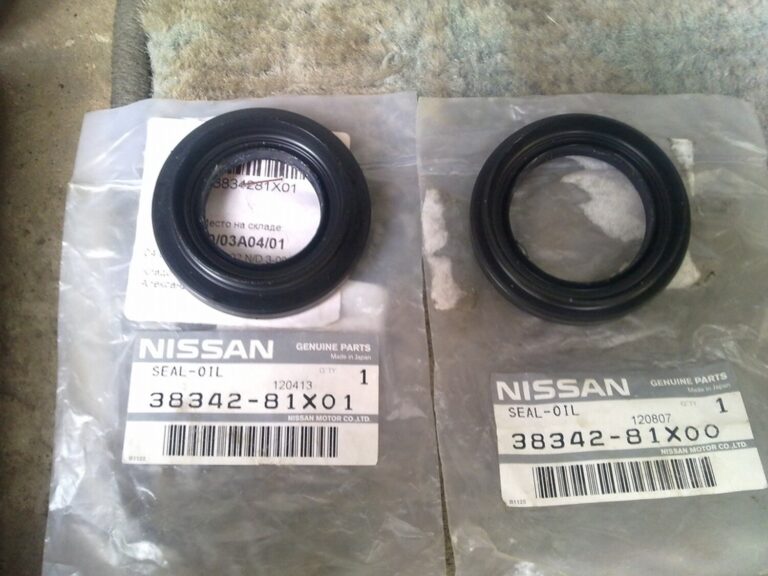
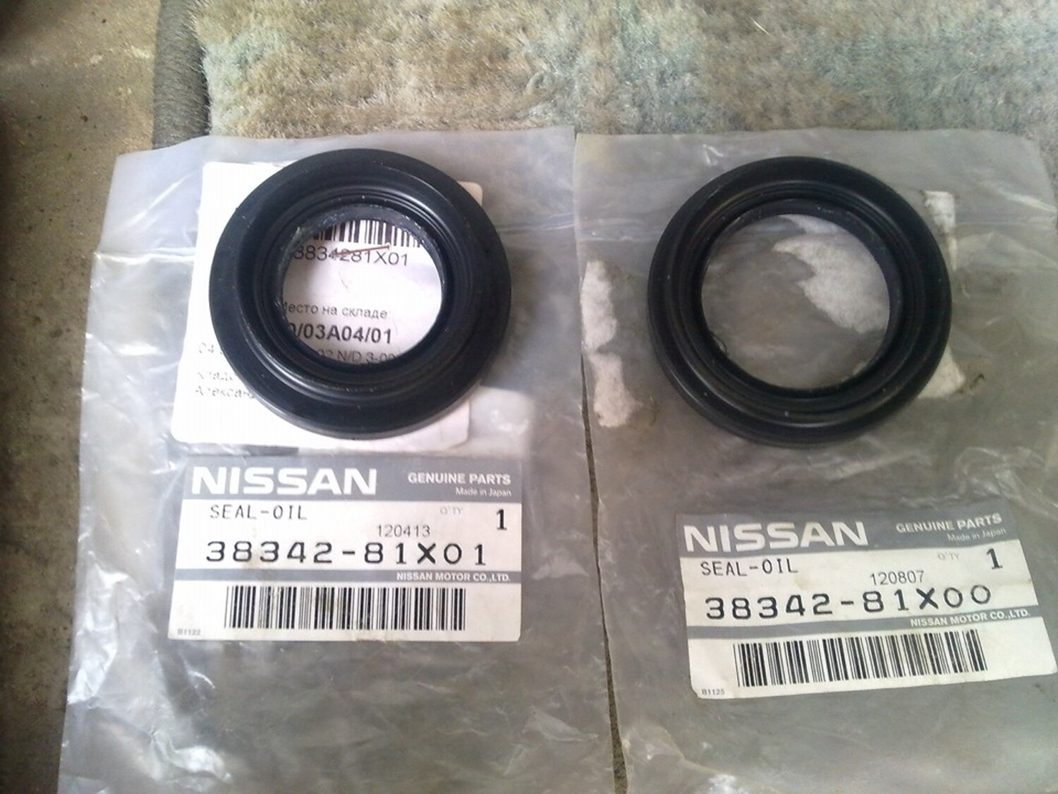
OEM Driver Side Part Number: 38342-81X00 Alternate Non-OEM Part Numbers: Timken / O’Reilly – 710118 Part Description: SEAL-OIL, Nissan Driver Side Output Shaft Seal / Differential Transmission Case Price: $8.00-$9.00
OEM Passenger Side: 38342-81X01 Alternate Non-OEM Part Numbers: Timken / O’Reilly – 710124 Part Description: SEAL-OIL, Nissan Driver Side Output Shaft Seal / Differential Clutch Housing Price: $8.00-$9.00
Input Shaft Seal: 32113-03E00 Part Description: SEAL-OIL, Nissan Input Shaft Seal Price: $8.00-$9.00