Community Member Credit: David Colaire
![]()


Member Credit: tjmoney87
Overall, this is an easy mod if you are careful, but if not, things can get ugly VERY quickly! I would recommend getting a second cluster just to practice…that’s what I did, making sure I was careful enough and to make sure the strip fits. I like it because the cluster lights in ACC mode, but that’s a personal preference (also because the cigarette lighter powers in ACC mode). Also at night, they are BRIGHT (but not bright enough to blind), and do not dim, unless you get a standalone rheostat, I may get one later…I wish I would have got an orange or red one, it would have really nice, but I can always change it out LOL… Also, I would recommend the Maxima’s clear outer cluster cover, http://www.courtesyparts.com/24813-c…3-p-47148.html, our tinted cluster cover would dull things a bit…
Difficulty: 7/10
Pros: LED strip brighter than EL tube, no more dim cluster on one side !
Lights in ACC mode (personal preference). Several colors you could use (again personal preference).
Cons: If you are not careful, things can get ugly quickly! You will have to buy the Maxima’s cluster to enjoy the LED cluster.
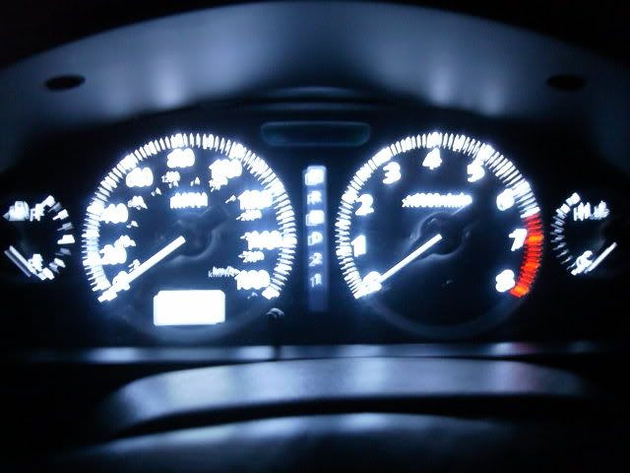
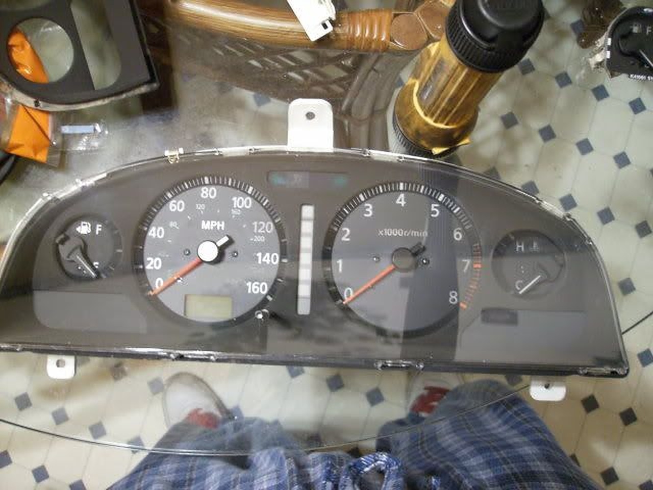
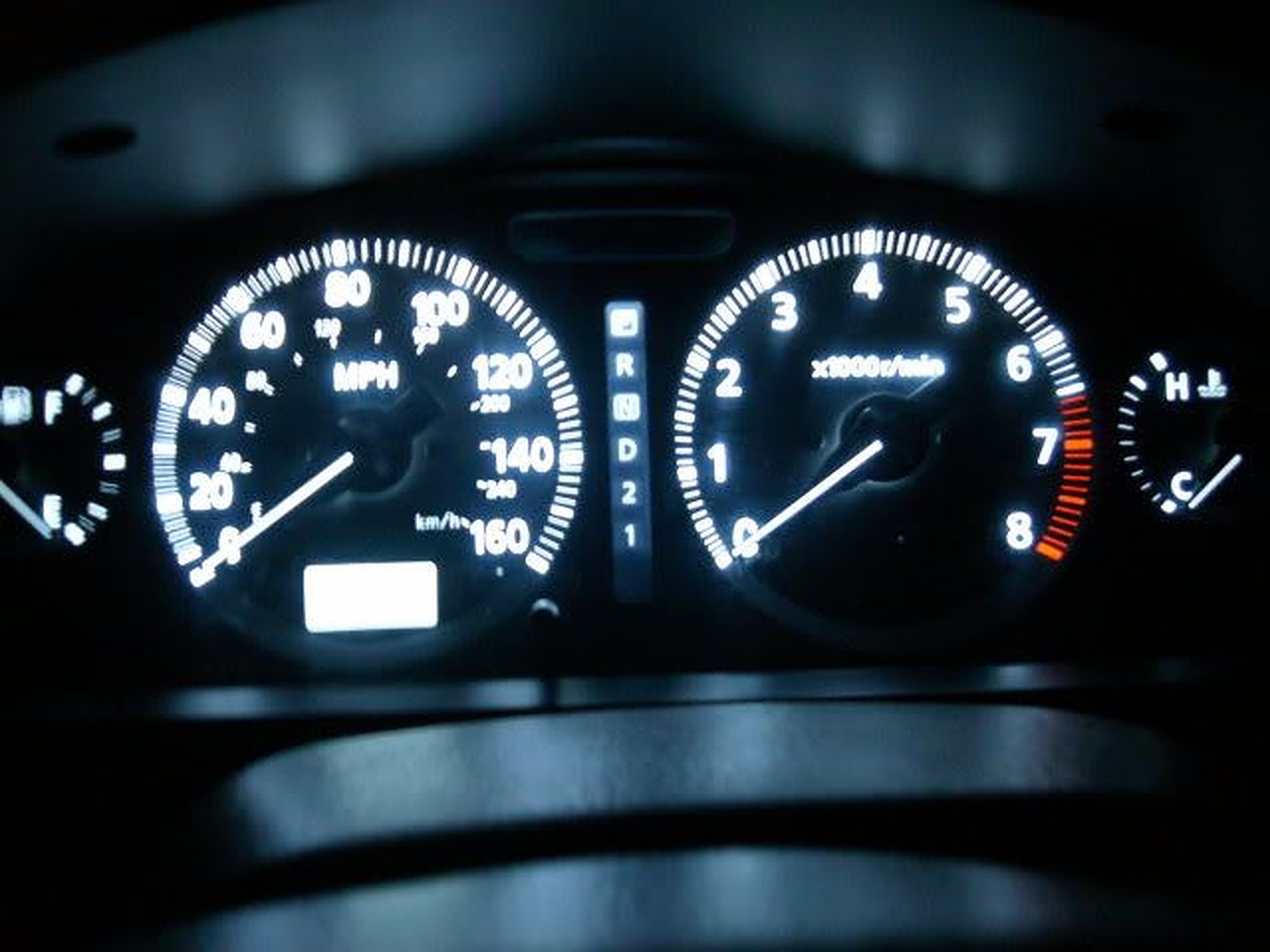
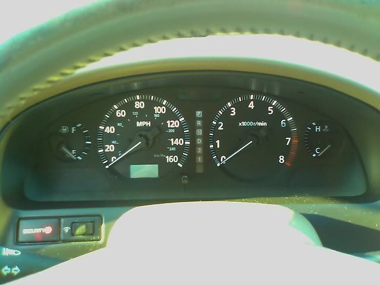
Stock
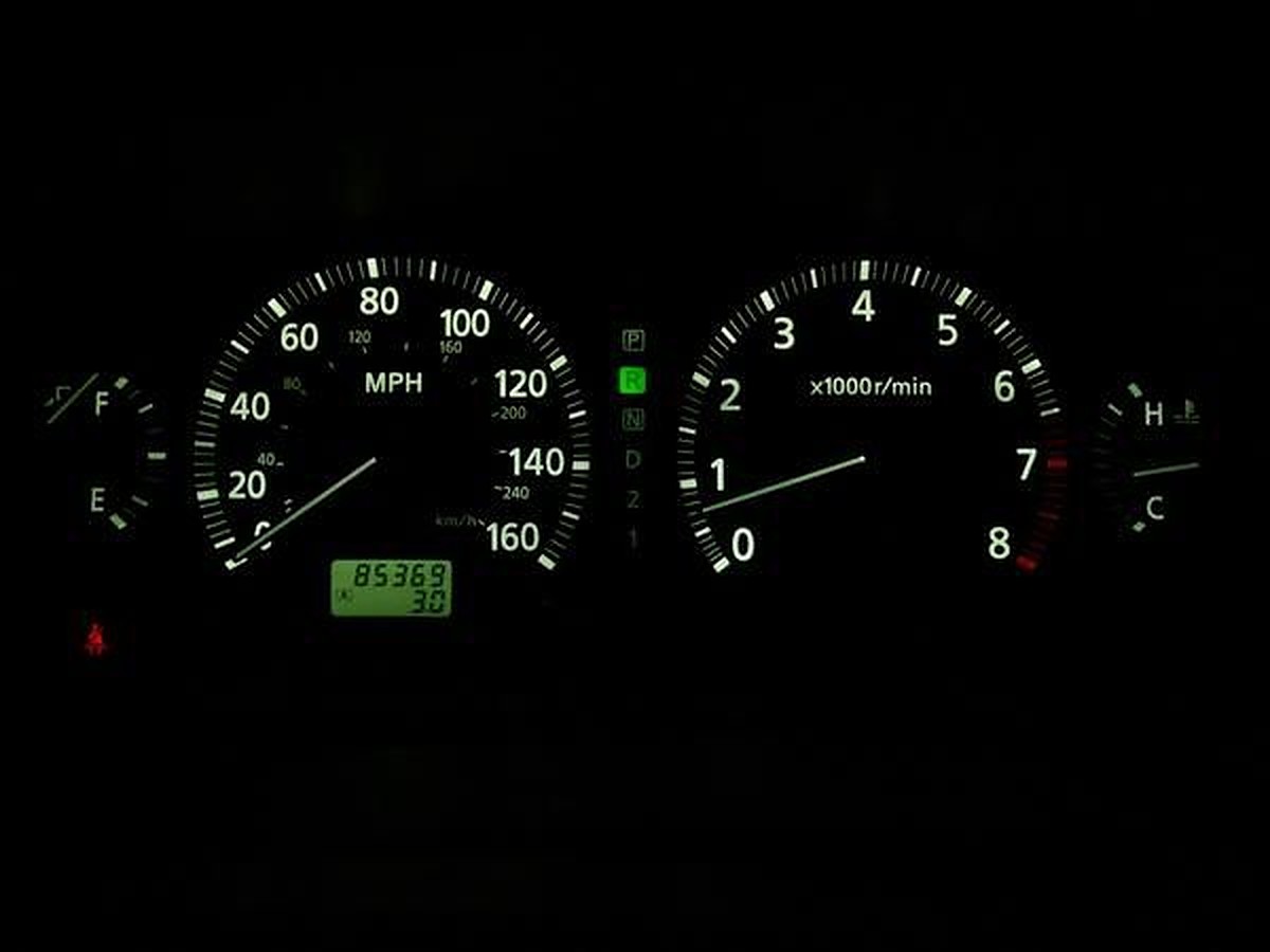
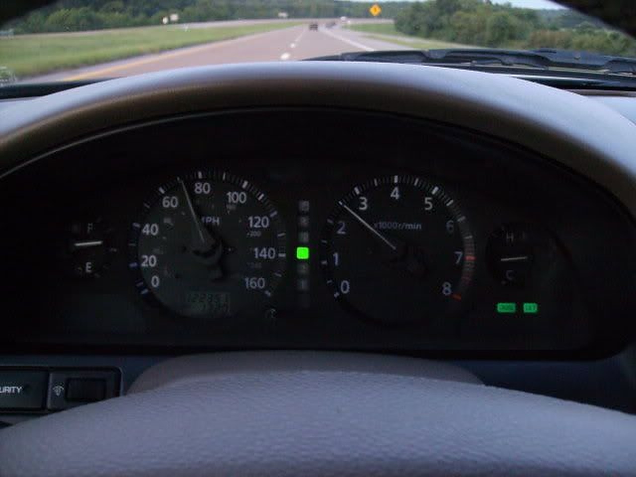
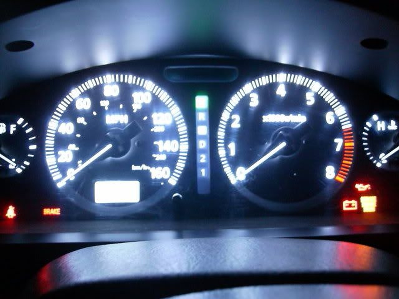
After LED strip swap
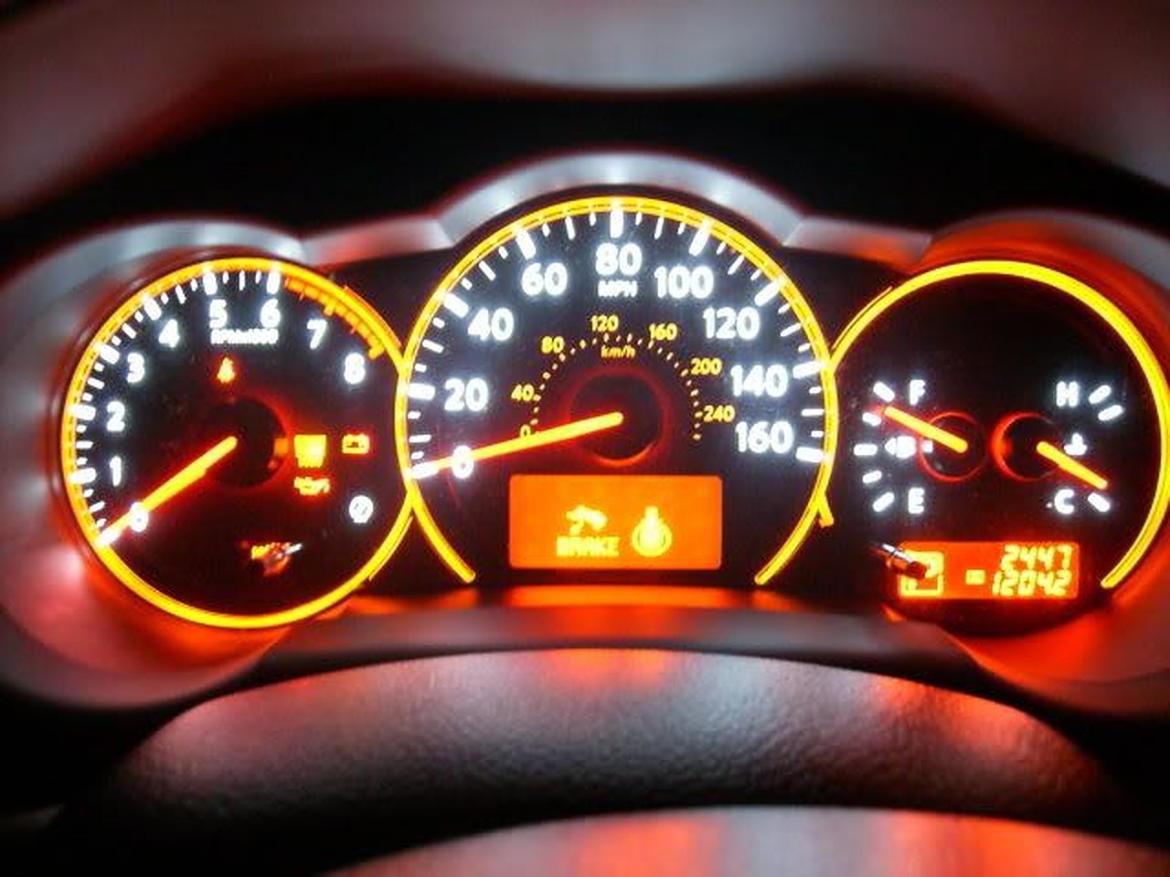
My mom’s ’09 Altima
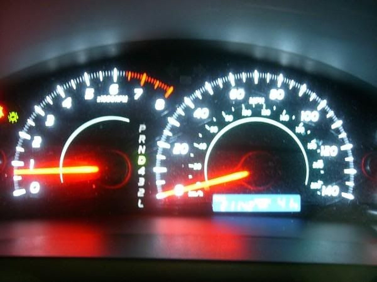
An ’09 Camry
1. Take the cluster out of the car (this should be self-explanatory).
2. Take the outer cover out of the cluster (be careful, it is easy to break!)
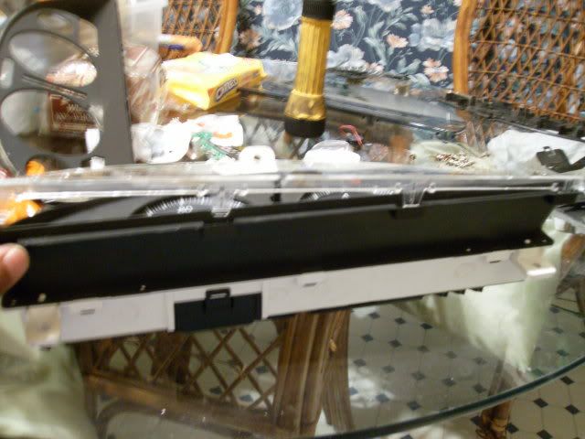
3. Remove inner cover (black part) out of the cluster.
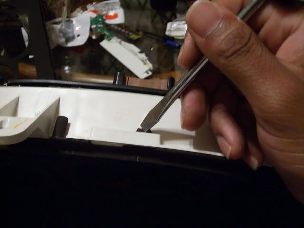
4. By now you should see all of the screws to remove the gauges.
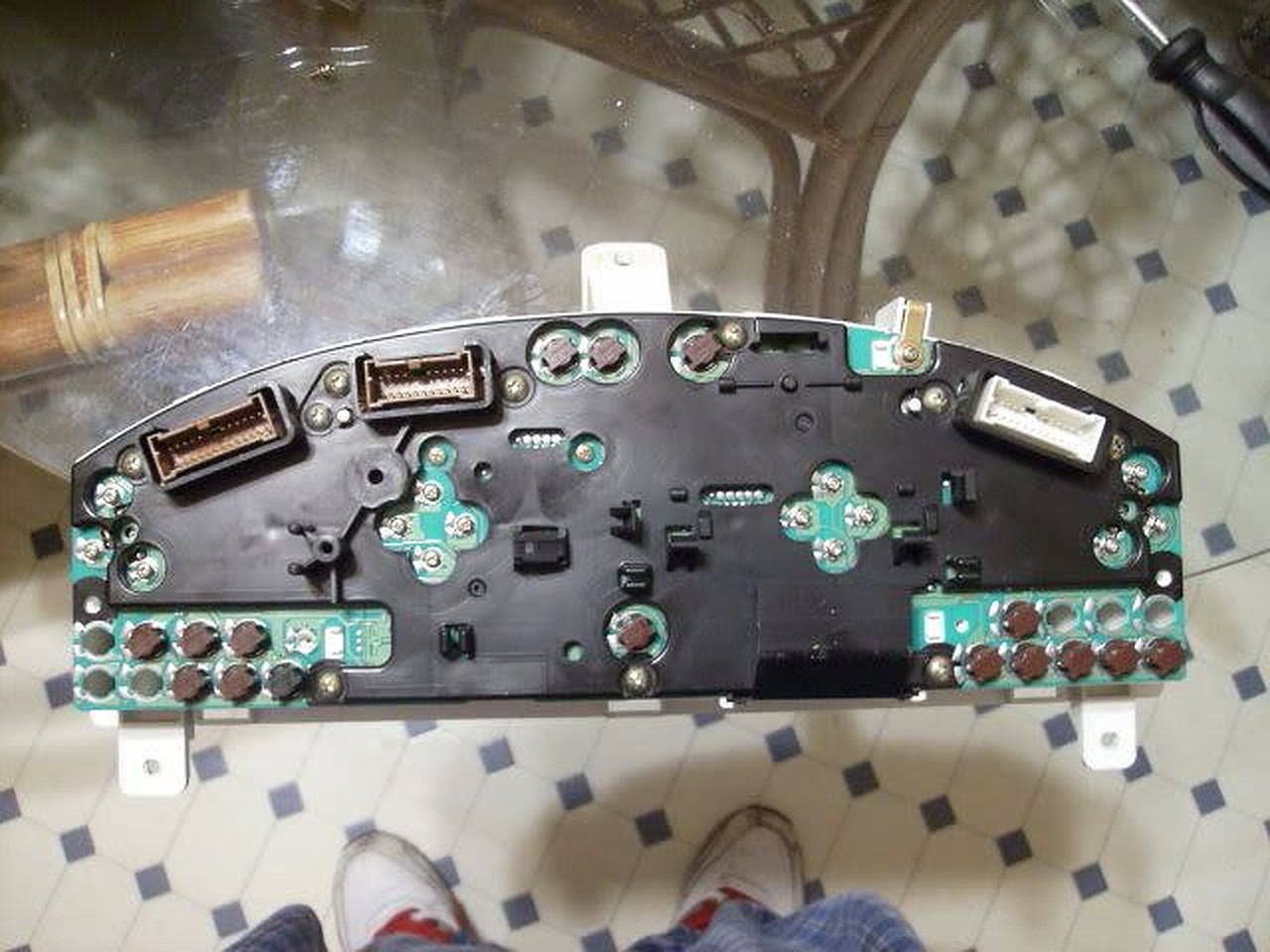
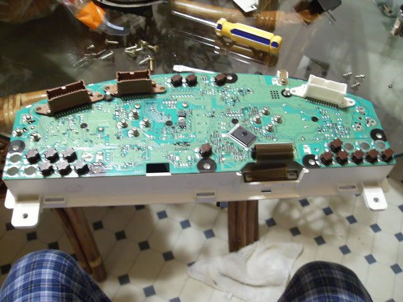
5. Removed the circuit board cover to make everything easier…
6. Here you can keep the gauges together as one after pulling up, or you can have them separated (which I did) by removing screw on the bottom of the speedo and tach.
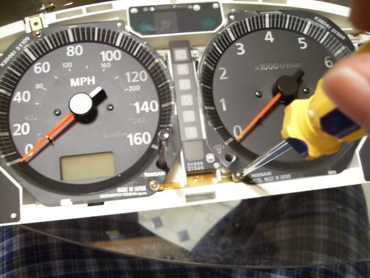
7. Before removing speedo head, remove odometer head. PLEASE be careful, that odo head is on their pretty tough it would be easier to break the tab rather than the odo head!
8. Here is the EL tube and all it’s glory…
9. These are the screws to remove the EL tube…
10. Pull up on the tube assembly and it should come out of the cluster’s circuit board.
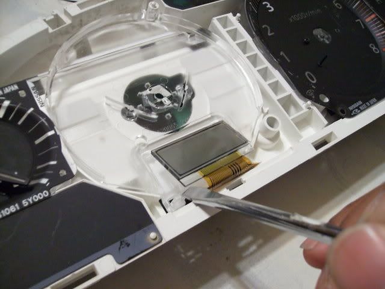
11. Here is the room you have to work with…it’s not much, but the LED strip I ordered from http://www.oznium.com/led-flex-strips fit like a glove. I used super glue to hold it together. Also the wires from the LED strip can be snaked through the holes left from the EL tube screws…
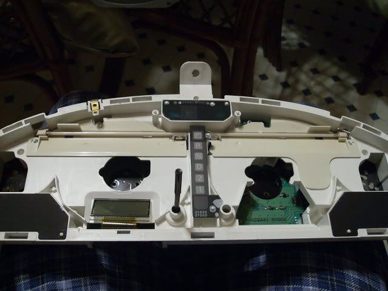
12. Put everything back together and tighten everything up. Use a 9V battery to make sure the strip lights up…
13. With everything back together…
It’s wasn’t bright at all (especially in the daytime) but it was on a 9V battery so…
I decided to wire it up to the cigarette lighter…yes the gear shifter surround has to be removed and the radio/ climate control too, or enough to get to the cigarette light wires…
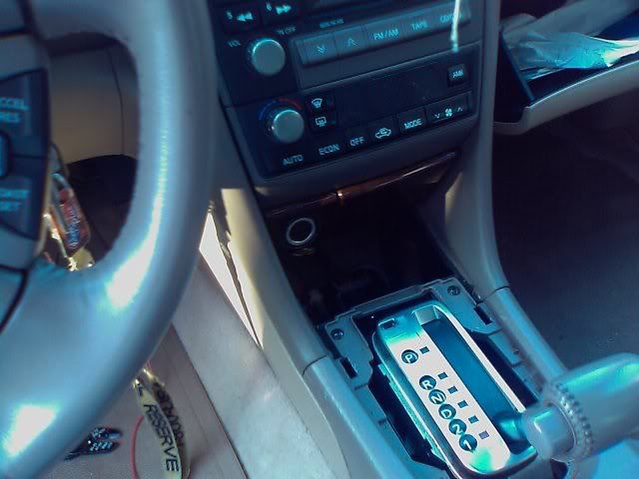
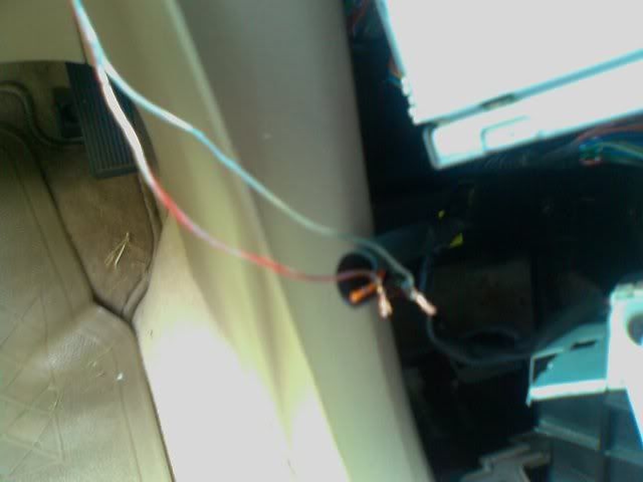
Wire the LED strip wires together with the cigarette lighter and put key in ACC to make sure it lights…it’s very bright in the daytime… Especially at night they are amazingly bright!
After only 4 years my replacement CCFL had dimmed to the point that I couldn’t see the display when the car was very cold. It was only poorly visible even when warmed up so I decided to finally install LED’s. I did this with a bit of hesitation because I could not find the cluster wiring points for LED’s posted anywhere, despite hours of searching. With some work I was able to figure it out.
The LED strip and an extra connector was purchased from superbrightleds.com for less than $20 with shipping.
1 – NFLS-NW30X3-WHT Natural White LED Strip (includes 1 connector)
1 – NFLS10-2CPT Pigtail Connector
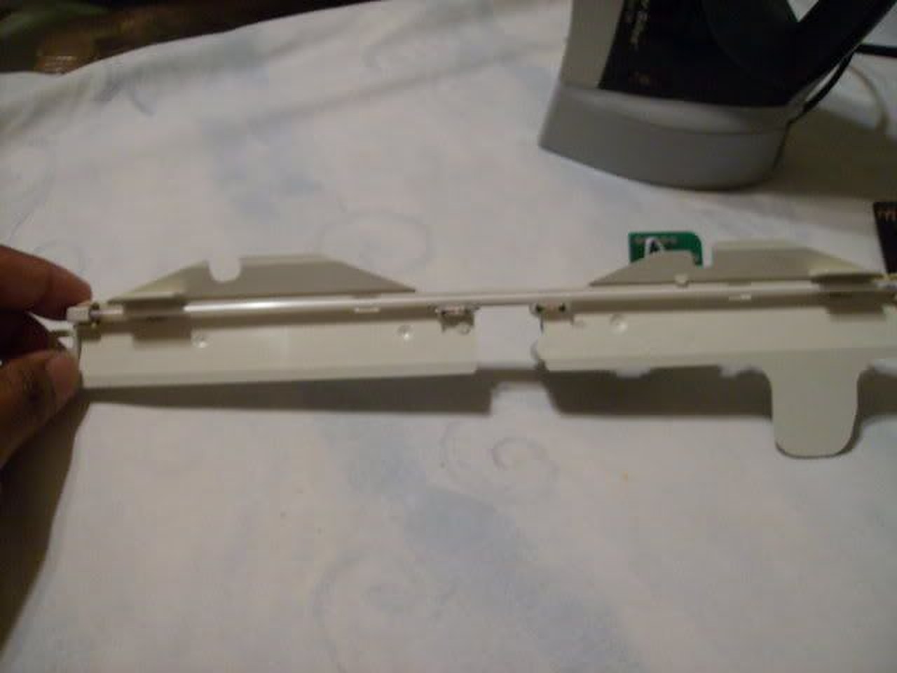
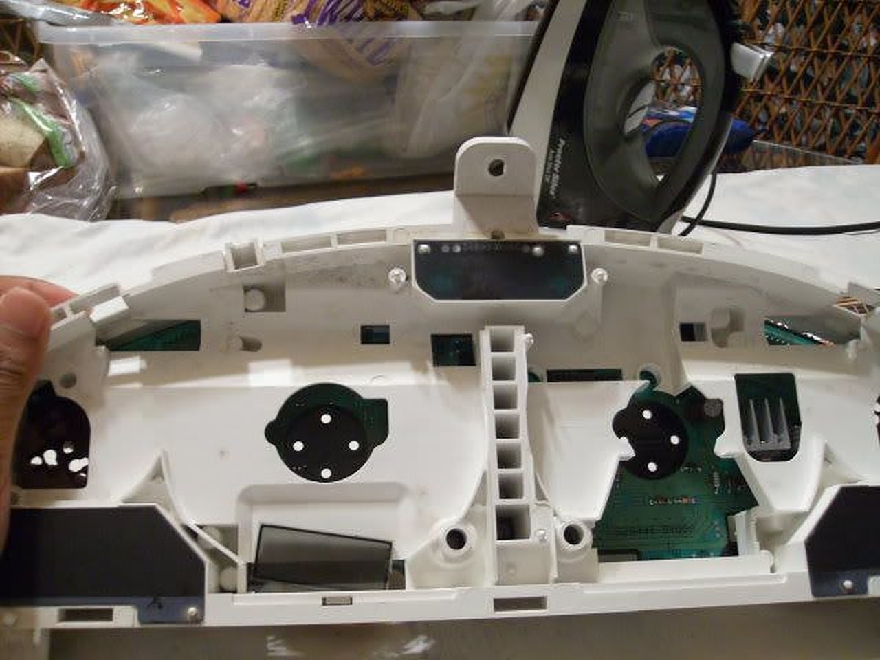
The LED strip has adhesive backing and can be cut every 2″. I pulled the old CCFL, associated wiring and circuit board and mounted two 4″ strips right to the CCFL plastic mount, one on either side of the transmission display. I placed them as close to the outside edge of the plastic as possible. They fit almost perfectly, only a tiny piece of plastic had to be trimmed from the mount. The wiring from the strips fit into the same run that the CCFL wiring ran through. I soldered the wires together.
I wanted the wiring to remain contained inside the cluster so I spent a few hours examining the schematics in the FSM and found the correct wiring points:
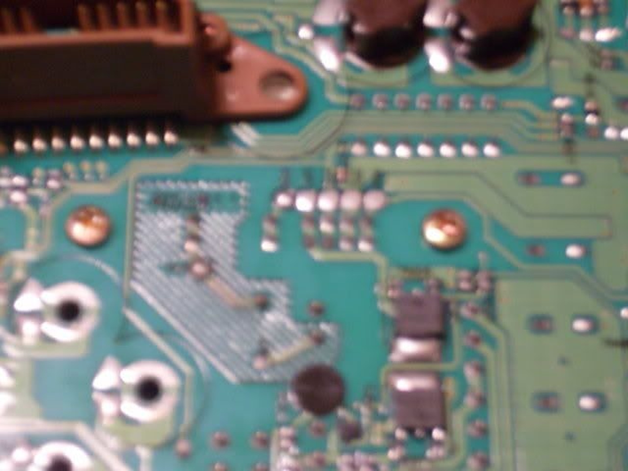
The wiring connection points are on the plug labeled M34, shown on page EL-145 of the FSM. It is fairly easy to solder wires directly to the pins on the base of the connector if you tin both the wire and pin first.
The negative LED wire connects to pin 49. That lead connects directly to the Illumination Control Switch (the dimmer control.) The FSM pages showing the wire endpoints are EL-120 and IL-123. The path of the wire runs across multiple pages of the schematic.
The positive LED wire connects to pin 66. Pin 66 connects to a 12V source that is controlled by the ignition key. It’s shown on manual page EL-147.
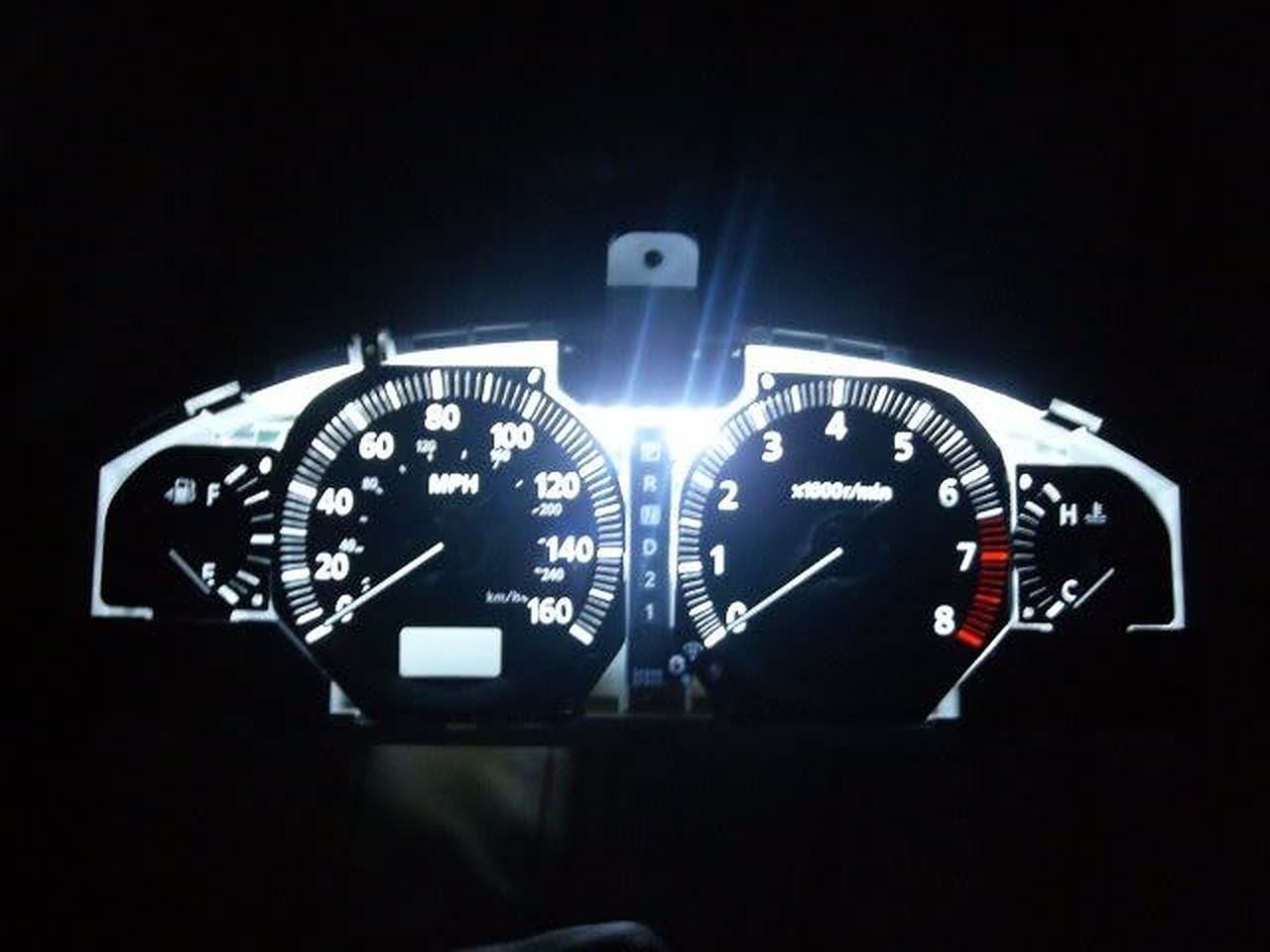
The results were well worth the time. For the first time the cluster lights look like they should, clearly visible in bright daylight even with sunglasses on. The odometer is also clearly legible all the time. When the headlights are turned on the cluster LEDs dim exactly as they should. The color of the LED strip is also excellent and lacks the purple hue of the last CCFL bulb I installed.
The only negative is very minor. The lighting across the display isn’t quite as consistent as it was with the CCFL. It is a minor variation and I don’t think I would have noticed it at all if I hadn’t been looking for it.
Good luck.
Update: After driving the car for a few days in the daytime and being very pleased with the brightness of the display, I drove last night after dark. The new LED’s are so bright that to get them down to a reasonable level at night requires turning the dimmer way down, too far down to clearly see the other displays that are also controlled by the dimmer. Unfortunately it won’t be possible to contain fully contain the wiring withing the cluster and maintain the daytime brightness without adding a custom circuit. To allow the independent control of the cluster LED’s I’ve decided to add a 2nd dimmer switch dedicated to the LED lights. Ebay had one for $12 shipped and I have an empty spot in the dash to install it so it looks like a stock control. I’ll post back here with results.
![]()

Credit: Fezzik (David Honey)
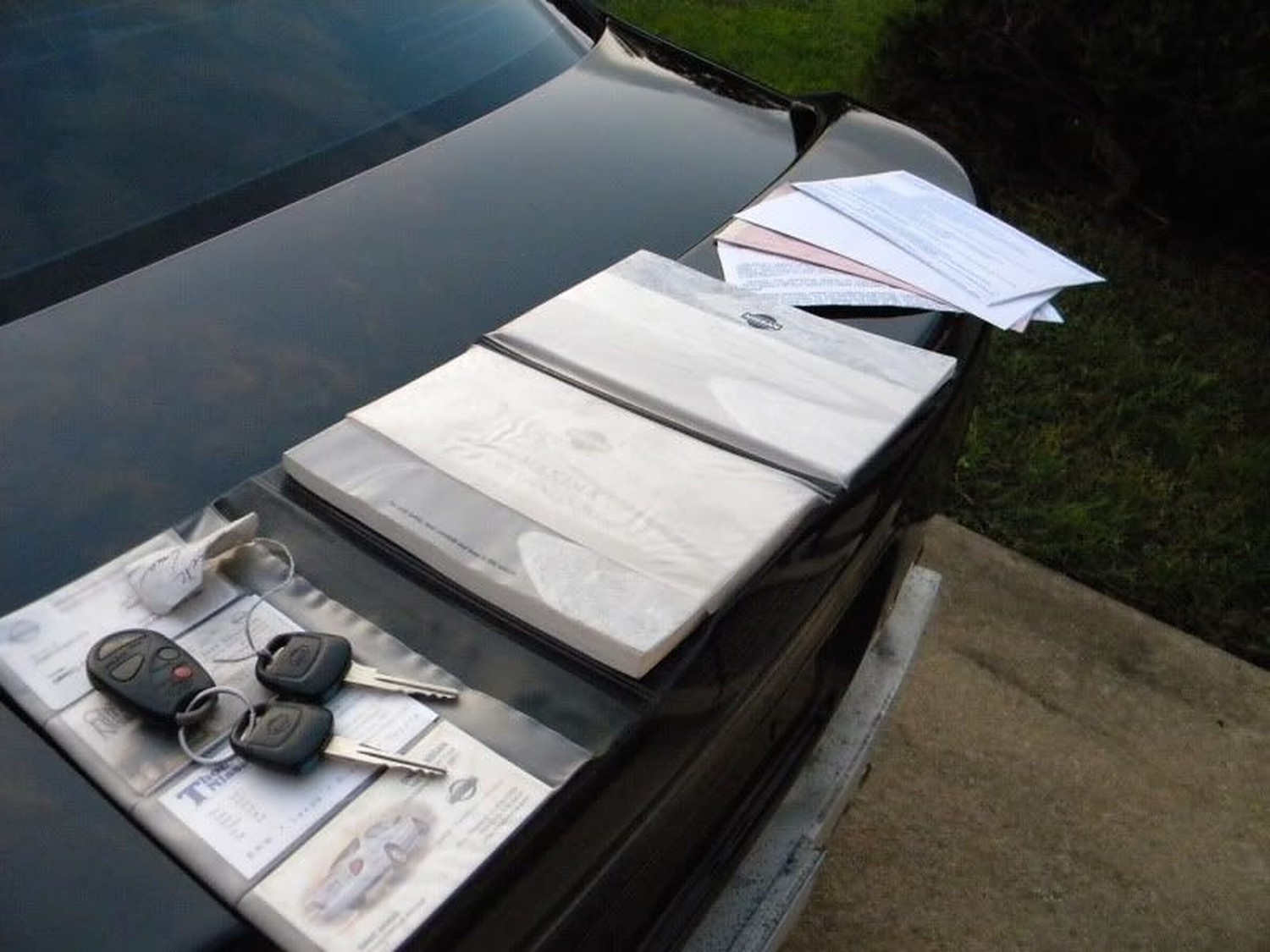
This is the How To on the installation of heated mirrors. A few things first before I go on. I have the automatic climate control with the rear window defogger switch on it. The side view mirrors are linked to this switch. For those with manual climate control, I assume that it is also linked to your rear defogger switch (RichK on maxima.org said he got the same reading as I). Total costs are as follows quoted from Dave Burnette (1-888-254-6060):
Mirror Heater Relay = $12.22
Side view mirror glass with heating element only = $45.72 per side
First of all. Make sure you do not have the heated mirror option. To make sure, you can either press the rear window defogger switch and put your hands on the mirror to see if it gets warm or pop off your side view mirror glass and see if you have wires running to the mirror itself. If you do, then you have this option already. The picture below is one showing the difference in the two mirrors. The right does not have this option and the left mirror does. You will have to purchase the mirror on the left because it has a heater element built into the glass mirror.

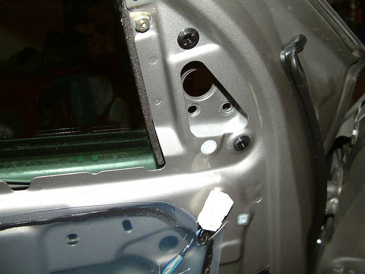
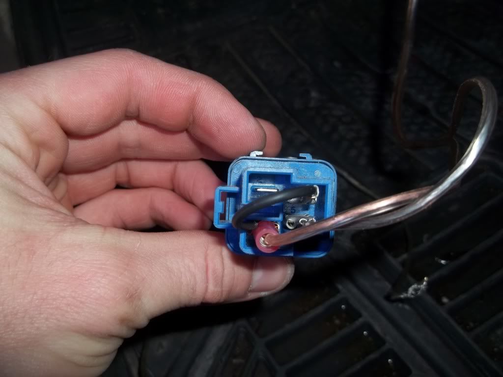
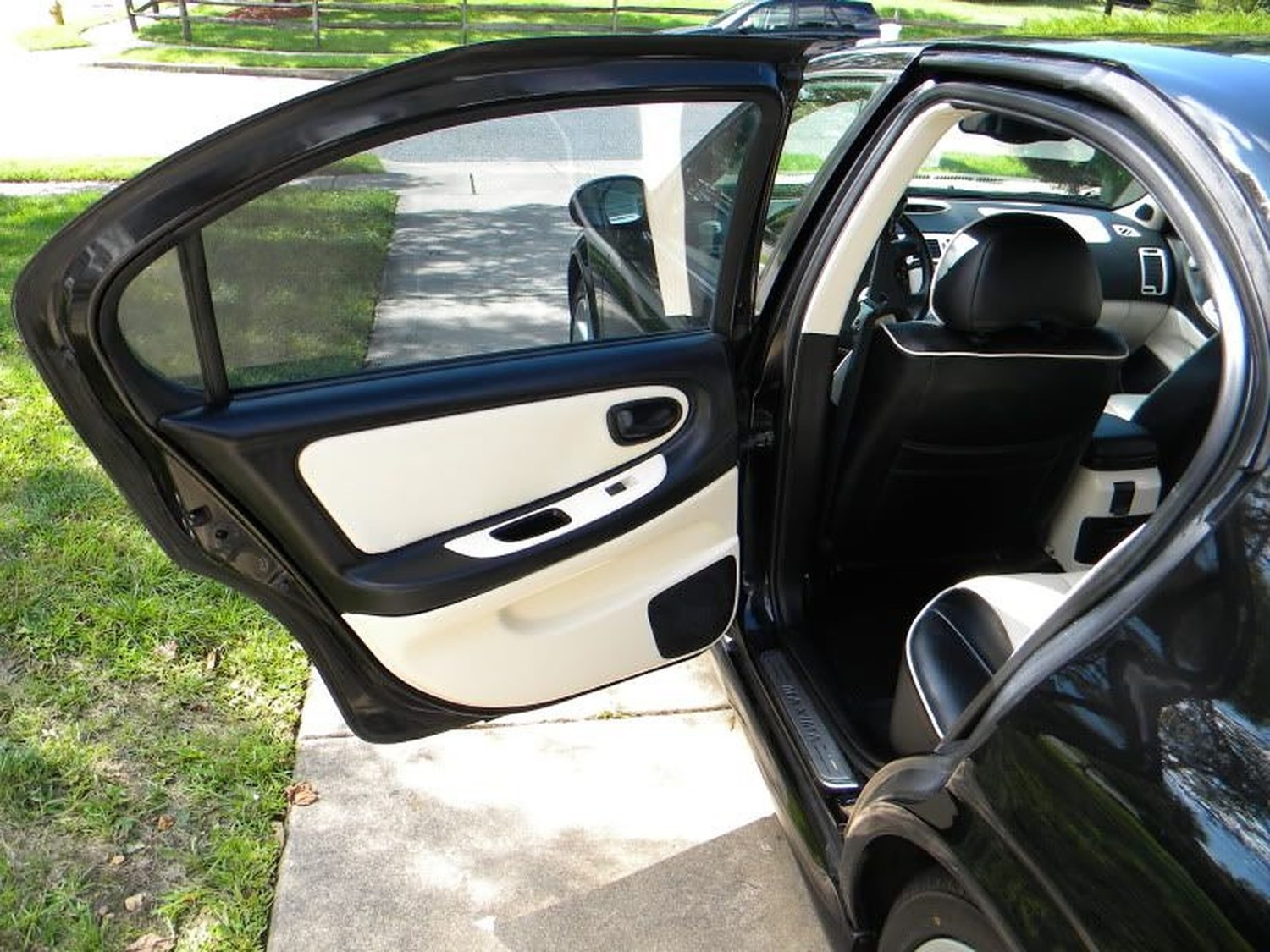
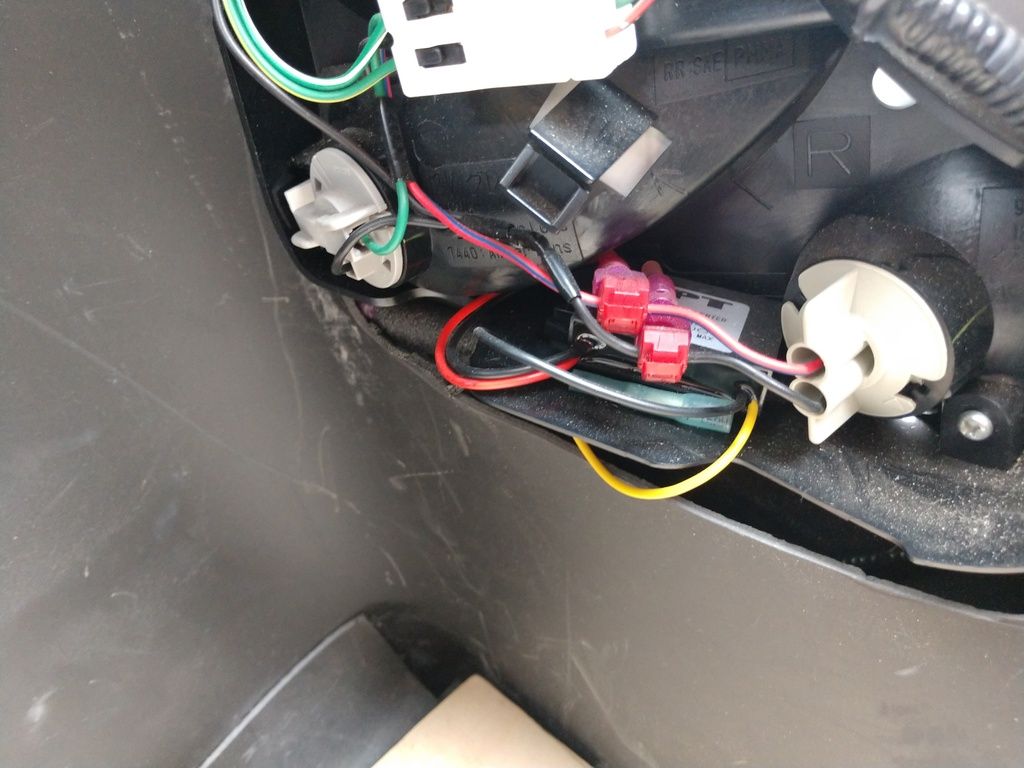
If you do not, then follow these instructions to get them. First of all, open your hood and when looking at the engine bay look to your left and you will see a black box that contains some relays. Open that up and find the corresponding spot for the heated mirror (it says on the black box where its at.) If you have a spot to put a relay in then all is well so far, and later you will have to buy the relay or in my case I had a nice surprise and already had the relay there. Ok the next criteria you need to find out in order for you to proceed is to take off your door paneling and look at the wiring harness going to the side view mirror (see below pic). The big black plastic piece is the cover to the side view mirror. There are 3 wires (yellow purple and dark blue) going into this and into the side view mirror. There are 3 wires corresponding to these wires on the other side of the connectors. Now take note of the other 2 wires (Green and light blue) coming out of the top right two holes. There is normally nothing here, but on the corresponding other side there are two wires leading up to these.

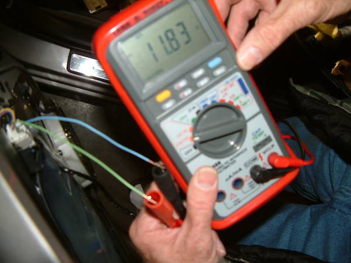
These are the wires that are pre-wired for the heated mirror. I tested this theory out by hooking up a voltmeter to the wires that I put in the top right holes. (I originally had the connector in the above picture disconnected and tried to test the voltage on the 2 small pins and that was too hard to do. I shorted the circuit and blew fuse 13… so do like I did above. SO much easier). When plugged into a voltmeter and with the rear defroster on I got around 12 volts (sorry about the blurry pictures):
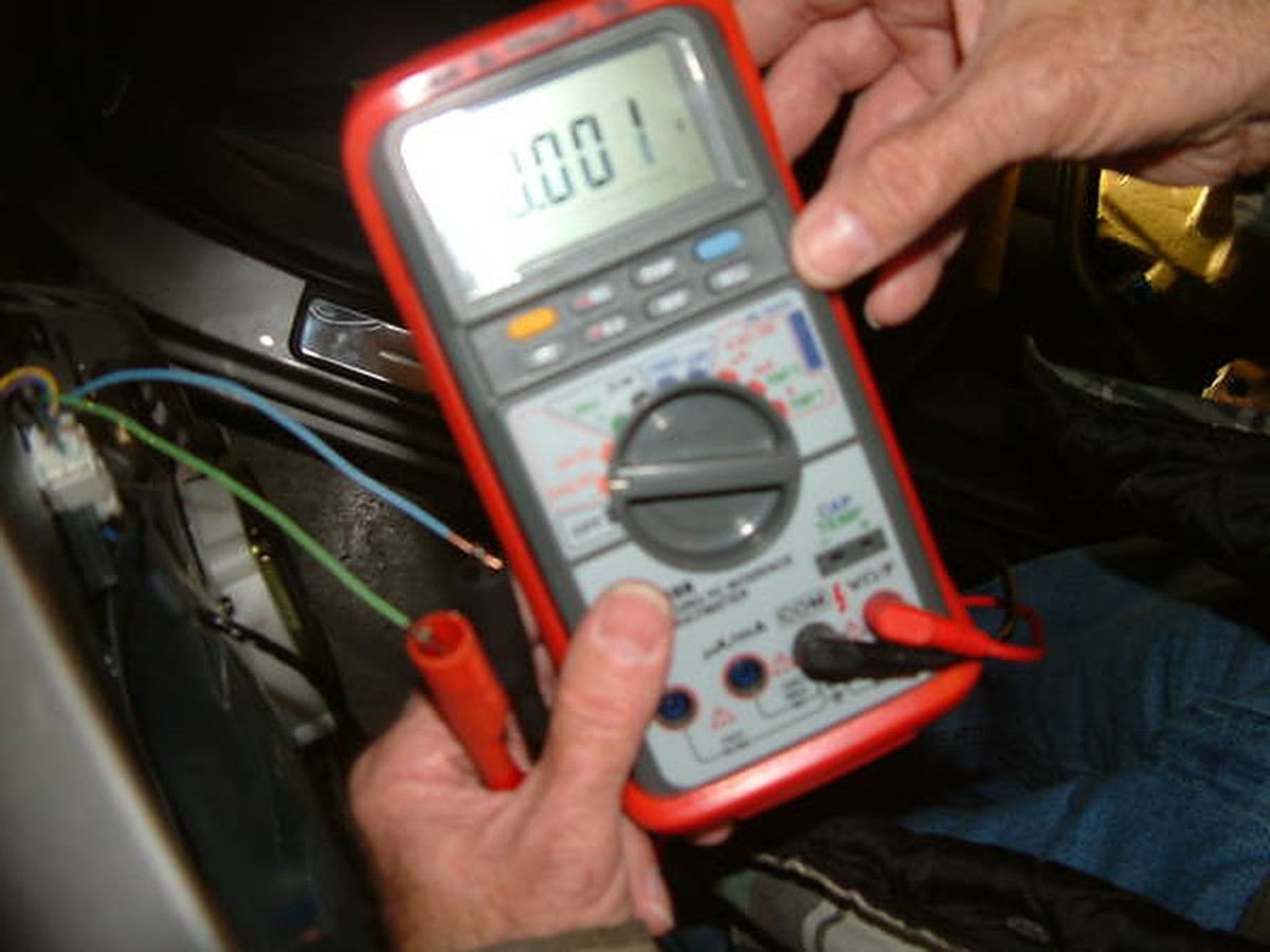
And with the rear defogger switch off reads 0.001Volts:
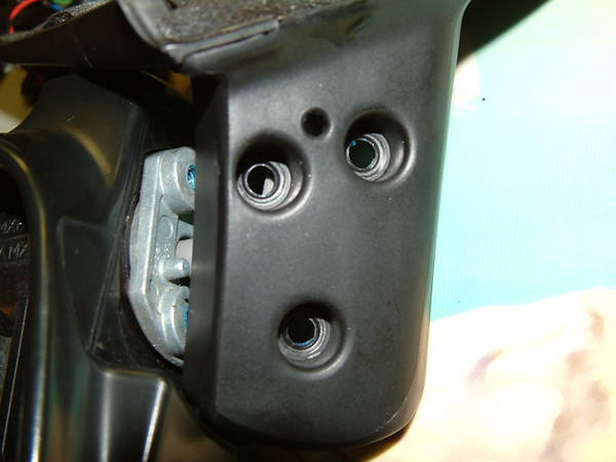
The next step is to take off the black plastic cover that is covering the side view mirror bolts (same plastic cover as seen in the above picture that the 3 wires are running into.) Unplug the connector, and take off the three bolts that are holding the mirror onto the door.
What it looks like with the mirror off (inside). Also notice how many wires are running into this connector. Look below the black tape. 5 of them.
Outside view with mirror off:

Now you have to take out the 3 screws that are below the side view mirror.Notice the blue. Yep that’s locktite. I striped the head of the screw on the passenger side and took me 2 hours to finally get it out. SO BE CAREFUL TAKING THESE OUT:
Here is the assembly all apart:
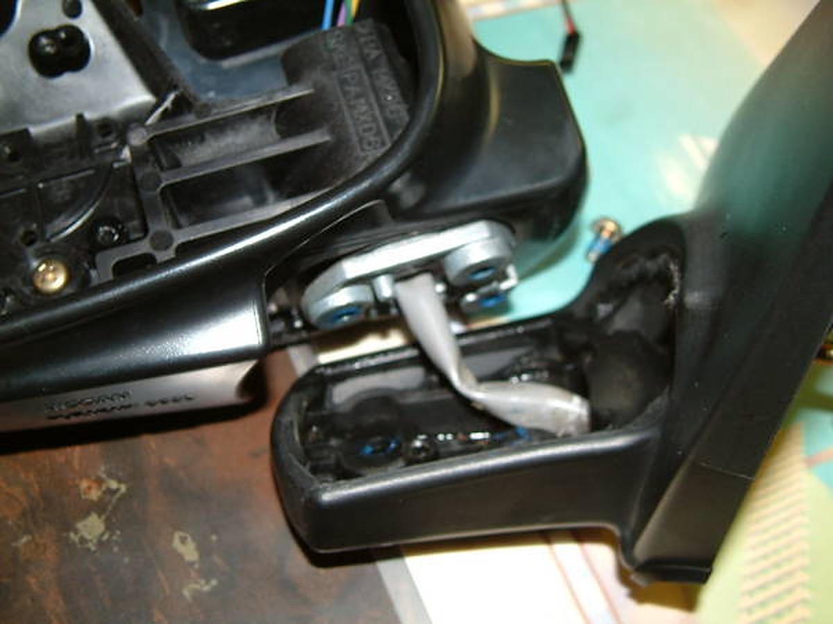
Now look at the part of the side view mirror that faces the car the part that has the 3 places to bolt onto. There is a cover on this that you have to take off. The insulation is glued on there so your going tear that. Nothing you can do about that. Look below how I tore mine. Unscrew the thing that is holding the wiring harness in place.
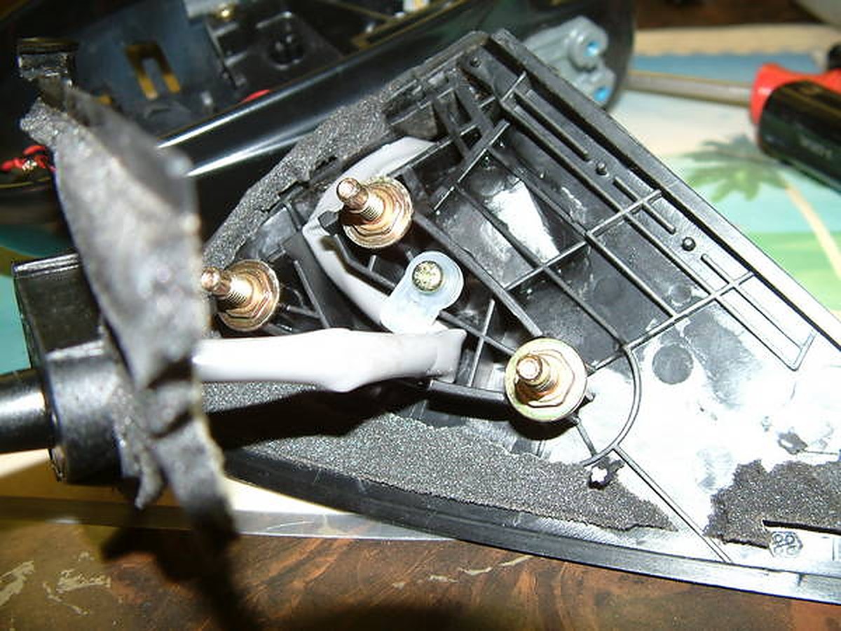
I apologize but I forgot to take some pictures from here on out. It was getting late. But now, you can have full access to this gray tubing. Remove the actuators (the things that make the mirror go up and down, right and left) from the side view mirror. This is held on by 3 screws. When you take this off you will see 4 wires. Didn’t I just say there was 3 wires going to the side view mirror. I did. But one is spliced somewhere in the gray tubing. Dave Burnette (You maxima guys should know him) and I were talking about this for awhile until I finally found out the reason The ECM even shows 3 wires but if you look inside the actuator, there is a wire that is split. Ok back to the subject at hand. Remove the 2 connectors (gray and black) from the actuator. Remember which go where. I marked it with scotch tape. Now the wiring can slide down the tube that is inside the mirror. Wish I had a pic of this but you will see what I am talking about. Now you can run wire through the gray tubing easily.
First I ran 2 wires long enough to reach from the other end of the side view mirror where the heater element connector is to reach all the way to the connector in the door panel.To run wire through this gray tubing was tricky, but I used solder wire. The stuff that’s flimsy. Well, it’s stoutenough to push the solder wire through the grey tubing. Then I tied ( you may try taping it) to the wire and pulled it through. You now have a wire going all the way through. Now put everything back together the way you took it off. I did not worry about the insulation from the above picture because it all went back and even though it is torn still covered everything up. Now that everything is back together you now have what you started with but, now with 2 wires running through the mirror. Here’s the part where I had to get creative. You have to have a metal pin connector to fit into the big plastic connector. Luckily I have a storage area of computer parts and wiring harnesses from computers. I actually got the 2 pins I need from a 1985 Honda Accord radio wiring harness for aftermarket systems. Lucky me. Now all that leaves is the connector for the side view mirror. Take a look at it below:

Of all things I found to fit into here… it was a long computer jumper. Sorta like the audio cables you plug from your cd drive to your sound card, but I had a 2 prong one. With a little bit of firm pressure it fit right in and quite snugly. Popped the mirrors back into place and I now have heated side view mirror option on my car. Supposed to snow soon. Can’t wait to try it out.
Special thanks go out to my dad for helping me decipher the wiring diagram on the ESM and reading the voltage, and to Dave Burnette for his time in this as well.
![]()

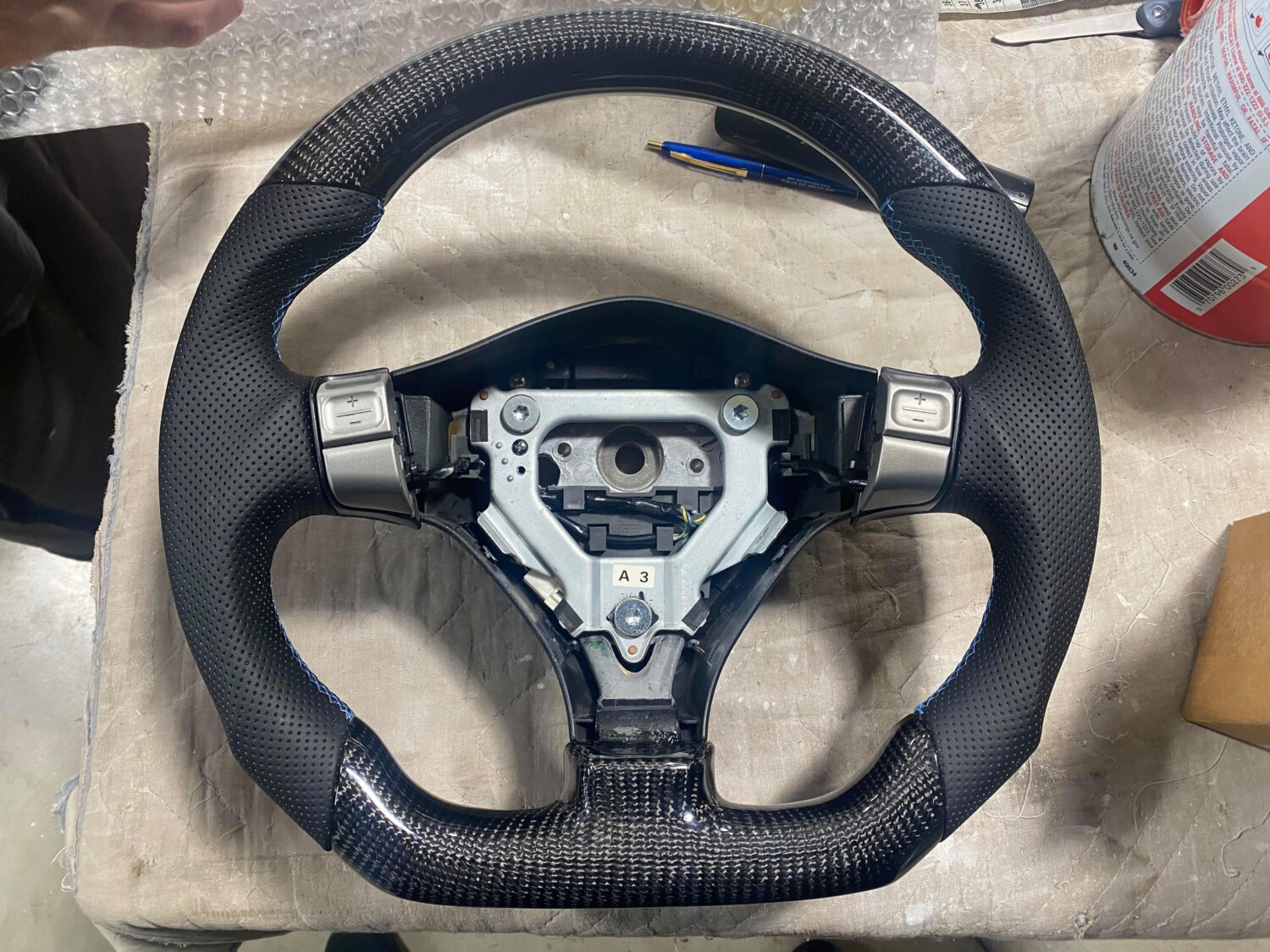
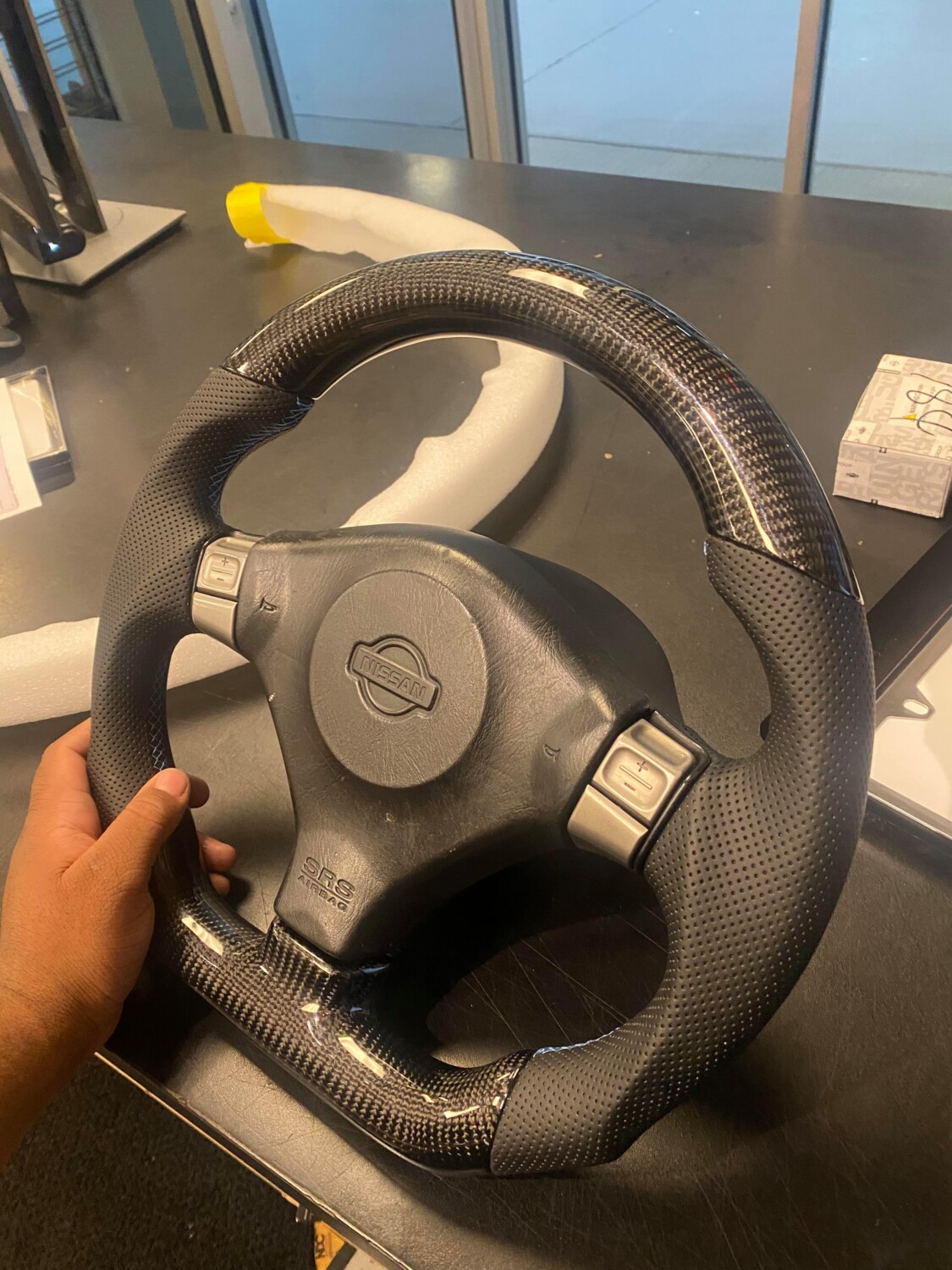
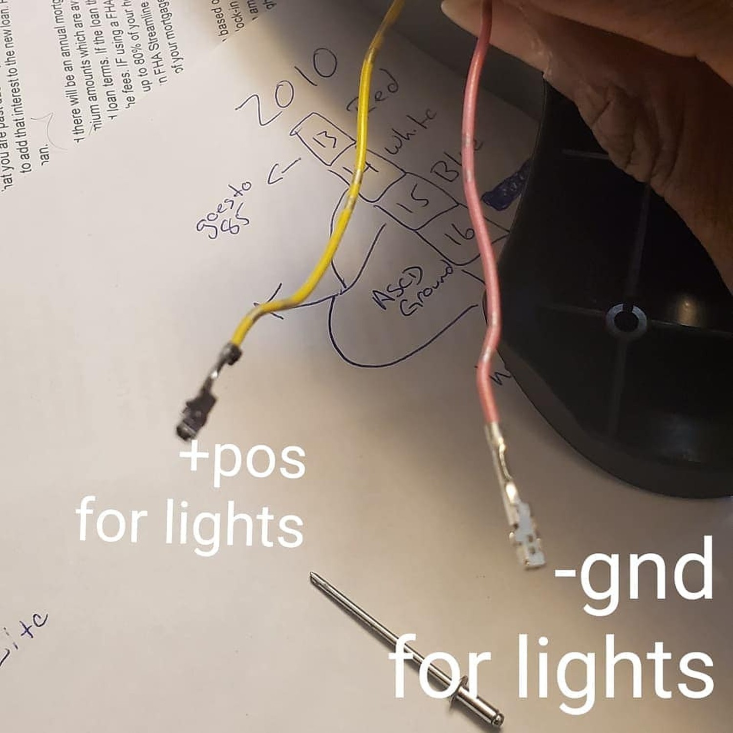
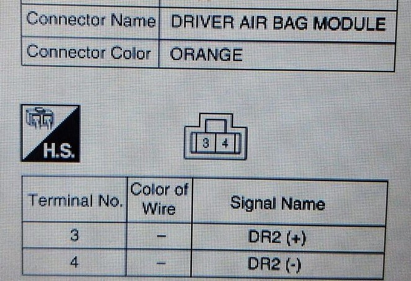
Member Credit: Douglas Sands / CGR$ Engine Initiative
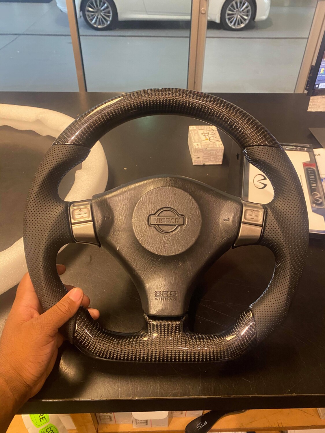
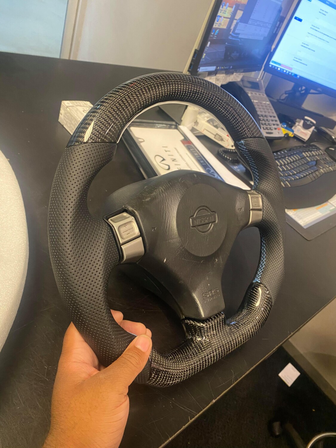
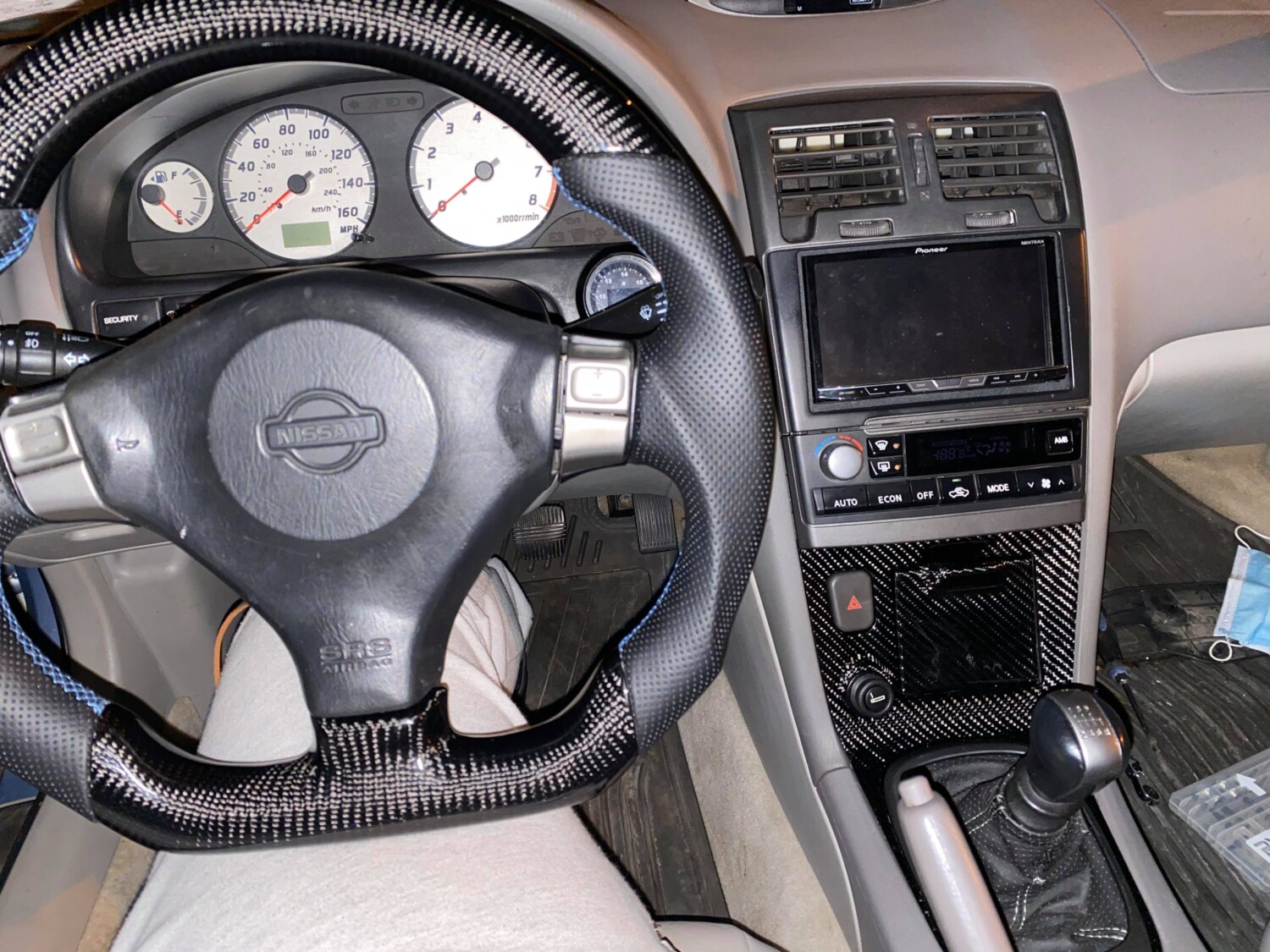
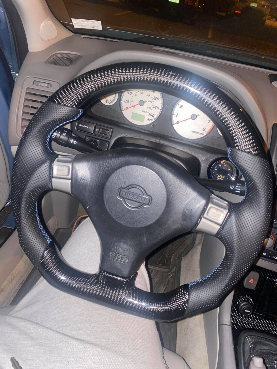
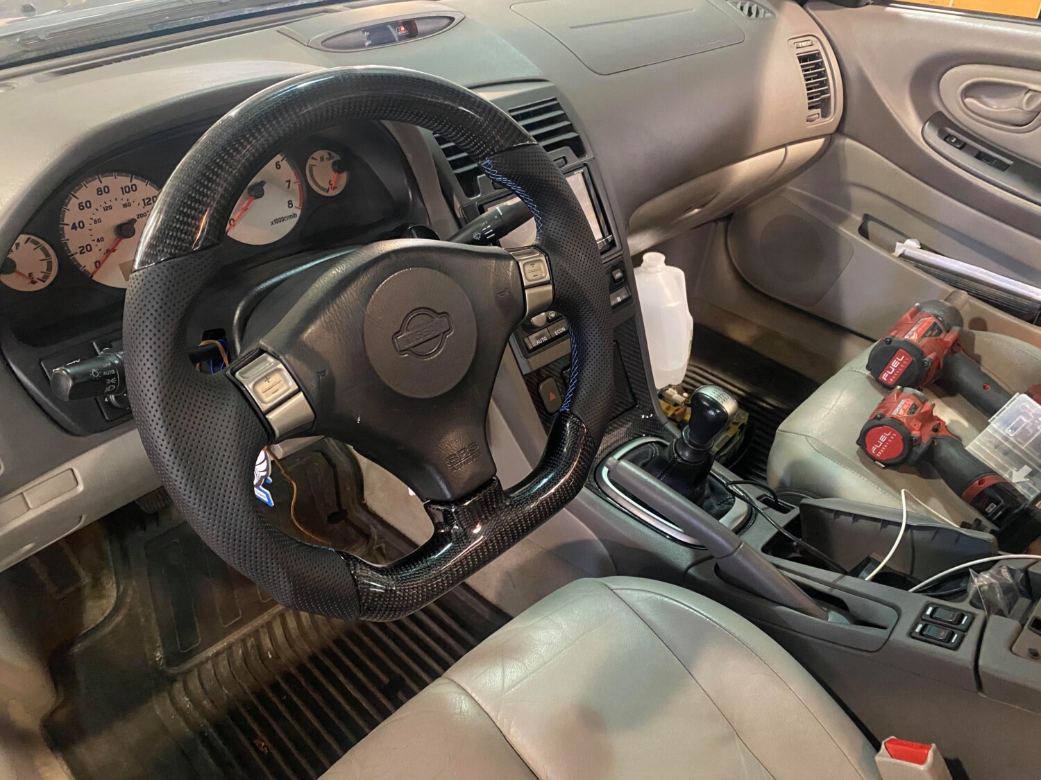
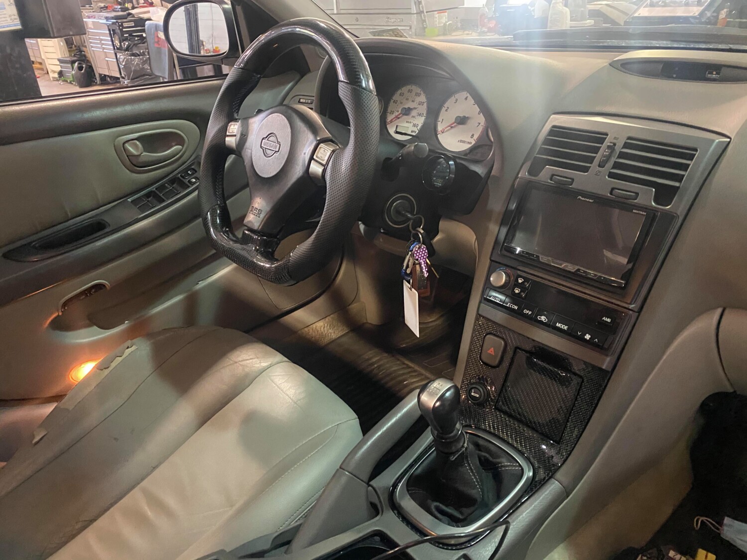
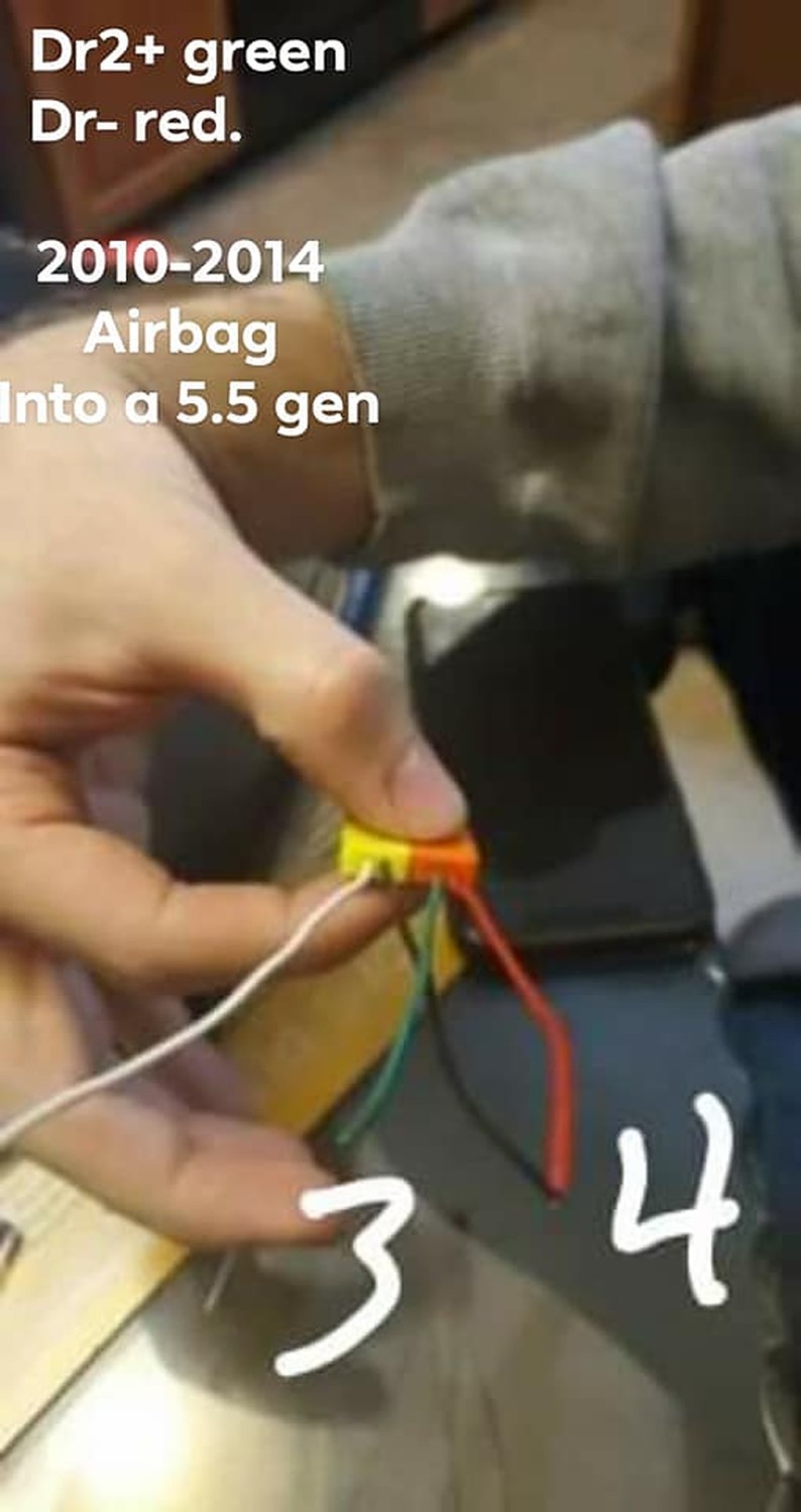
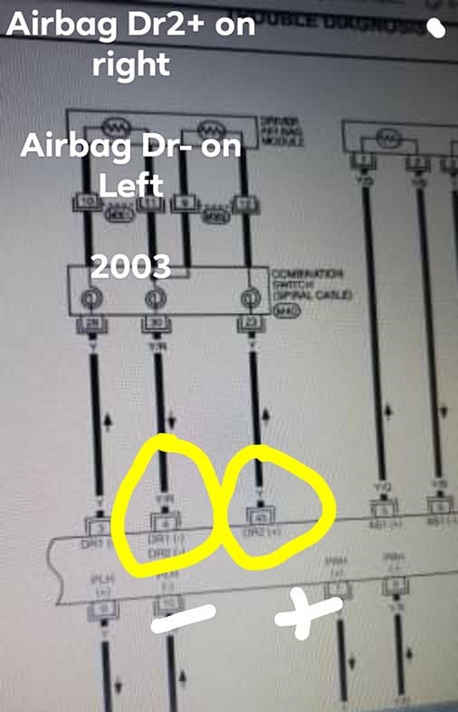
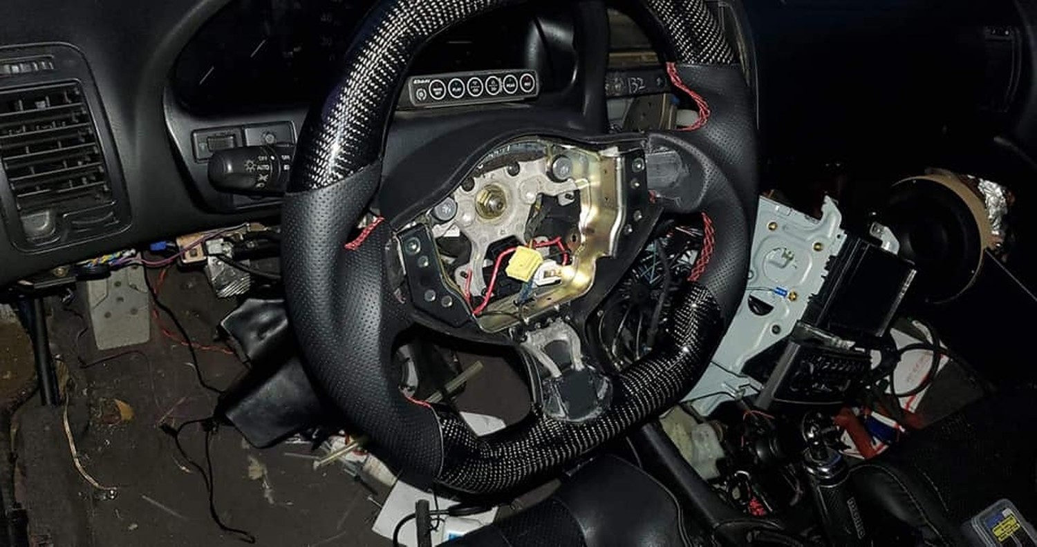
So you can use this info to set up whatever vehicle wheel to the 2003 Nissan maxima. This is a direct plugin for a 2009-2014 Maxima or 370z. I went with the max for the airbag symbol, didn’t need a huge z on my wheel.
These are the pin positions inside the vehicle. Just do the same for the other vehicle, and match them to their function. As long as the clockspring connector is the same just set it up and plug it in.
| Empty | 13 | Empty |
| Mode | 14 | White |
| Volume | 15 | Blue |
| Ground | 16 | Brown |
| ASCD Ground | 17 | Black |
| ASCD Switch | 18 | Red |
| Empty | 19 | Empty |
| Horn | 20 | Green |
| 2007 Horn to 2003 Clockspring | ||


![]()

Member Credit: TunerMax
I know some of you were interested in wiring your Map light(s) to illuminate when the Dome turned on, and some of you already have. Either way, I thought I’d let you know what I’ve figured out.
The best way I see to do it properly:
Tap into the ground wire (Dome light to SECU [Smart Entrance Control Unit]) Terminal #31 between the SECU and Dome light and install a relay there. I’d do this AT the SECU, most room to work. You want to hook this into the trigger side of the relay.
Here is the location of the SECU:

Then run a 2 Wire cord (preferrably one line with a tracer) from there, up to the Map light (up the Left A pillar and over).
The switch Wiring in the Map light seems to differ. I found 2 set ups.
1. On my car it’s a Single Map light, and it is wired with power to one side of the switch, then when you press the switch power flows through the light and to ground. (standard switch set-up)
2. It appears on some models, with 2 map lights, power is supplied to the light bulbs, and the switches are installed on the ground side (makes the ground connection).
Hooking up the wiring for the first one is easier, all you have to do is attatch (solder) one wire to the bulb side (see wiring diagram), and one wire to the live (+) side. Then down at your relay, connect the wire you connected to live (+) to the relay, and connect the wire you connected to the bulb side on the other end.
Here is my amazing Wiring diagram of the new set-up:

The second way, you have to change the switch type for the Map light.
+ must be triggered by the push switch (before the bulb). That change is pretty straight forward, nothing real complicated, if there are any of you that don’t understand how to do it, post a good picture of your Map lights (unit removed, picture of the back side wiring) and I’ll show you what to do.
So with this set up, we have No diodes, everything operates normally, no extra bulbs. Only thing that changes, is the Map light comes on when the dome light illuminates
I thought I’d let you all know how to do it, in case you were scratching your heads on it, I know some of you have done different things to get this function, some pretty creative, some a little chinsy, anyways…
I know initially you’d just think, jump a wire from the Dome light, and if you don’t have a sunroof, I’d consider it.
I have a sunroof though so this is the best way I can think of (to have it operate properly without installing extra lights and non-sense)
Pull out the Map Light, and unscrew the Sunglass holder. Also pop the cover off the Left A-Pillar. This pic shows all 3 removed, and my wire fish run through already:
Now run your wire fish from the corner of the headliner on the A-Pillar side into the sunglass holder hole. You can probably use a coat hanger or just push the wire through, it’s pretty easy going, everything is framed in the corner.
Hook your 2wire cord onto the wire fish, and feed it through toward the A-Pillar

Now you want to run the wire fish from the fuse panel area (by pedals) up to the A-Pillar base (top of dash). Hook up again and pull through. This pic is with the wire already run.

Now the easy part Locate your SECU, remove the harness connectors (3) and move the wiring so you can work with it easier. And Use my Guide in the OP to locate the proper terminal. It`s a process of elimination to find the harness you want, mine was the middle one, I would assume all years will be the same. I know the terminal designation is the same.


Here`s the wire we want.

Now cut it.

That`s right, only genuine Nissan Parts Any standard SPST relay will work.


I kind of cheated with this wiring cause I ran out of female spades and I wanted to get it done. So the Constant power wire (has red insulation on it in pic) needs to be doubled up (split wire, add 2 female spade connectors). You`ll see what I did in the second pic


Above is everything hooked up except the Ground (terminal wire you cut). I Forgot a pic of the Crimp on the Terminal wire. You just want to join them together into a Female spade connector, you can see it pretty clearly in the pic below (red wire). Please ignore the crudity of the wiring install, it’s temporary, I’ll be installing a SPDT Relay to run my LED handle lighting, at that point I’ll be re-doing the wiring and mounting the Relay

Now, wire in that MAP Light. Hook up the Constant Positive wire (with tracer) to the Constant Positive connection at the Switch

And then hook up the intermittent Positive wire (no tracer) to the output side of the switch (to bulb). I didn`t post a pic of this cause I couldn`t get a good enough picture of it. Plug in the SECU harnesses, the MAP light and DOME light should come on (if you hooked everything up correctly, and the door is open)

If everything works, install all components and make sure all wiring, etc is secure. And enjoy your new modifcation every time you open your door or unlock your car!
Lights off:

Unlock button pressed, lights illuminate:

Door opened:

Just so you know, you can`t shut off your MAP light while the door is open, I don`t know why you`d want to though. It still functions normally when the doors are closed. Another great thing about this mod is, you can shut off the Dome light and have only the MAP light illuminate if you want to (kids in the back sleeping, but you still need light when the door opens) Enjoy!
![]()

Member Credit: perkman87
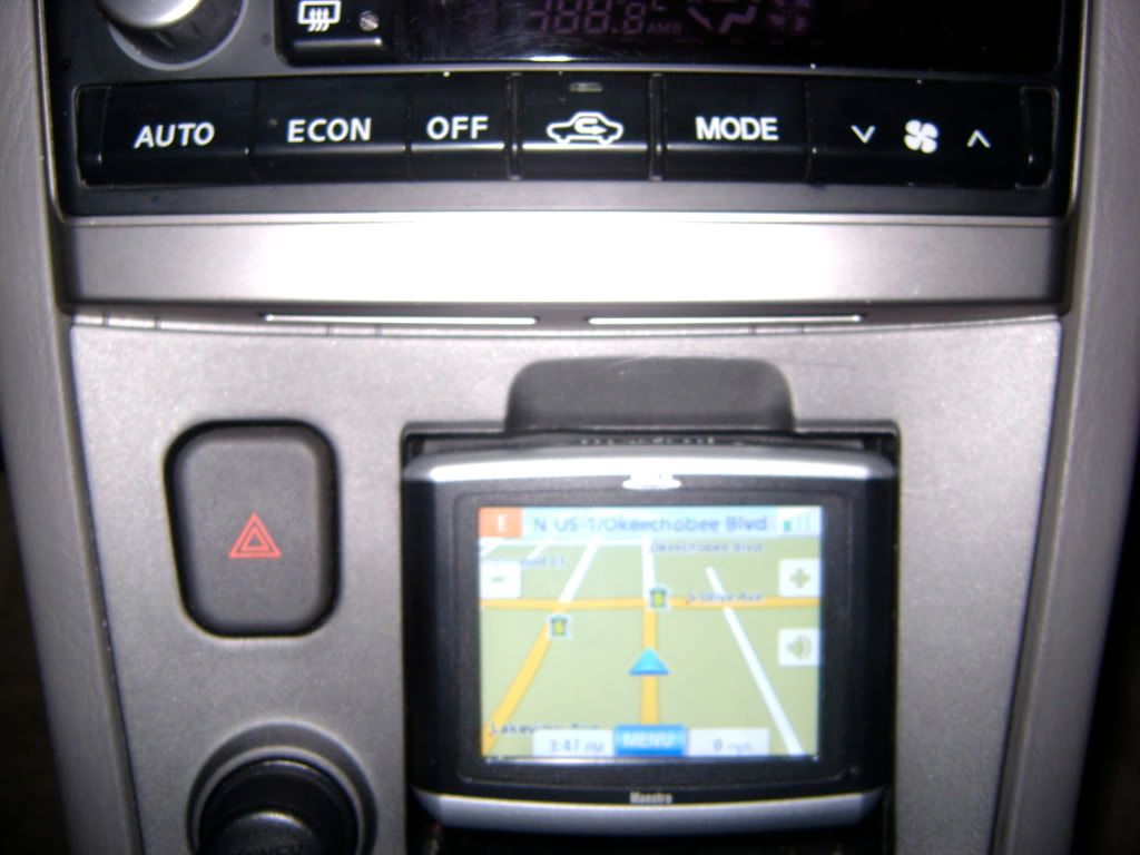
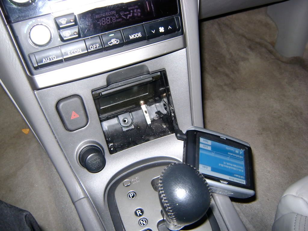
I have has multiple emails on the Navi install on my 2003 maxima via taking out the ashtray. The Navigation Model is the Magellan Maestro. It matches the TE edition perfect as you can see it is also silver and black just like most interiors in the SE family.
All I did was run the power from the rear socket spliced it in, then cut a small hole in the side of the ashtray holding container. Taking out the ashtray was simple you just unscrew the center screw in the middle of the ashtray, then pop the whole shifter cover off (holds ashtray) and there will be 4 screws that hold it in place, take those out and the ashtray box will come off with ease.
There are tabs on the side of the ashtray that will allow you to take the slider off with ease, then just go ahead and cut the side of the case with a warm knife, and slide the power connector through.
![]()

Owner: Metal Maxima
Year: 2001
Model: Maxima
Color: Black


SUSPENSION
Tokico Illuminas
H&R Drop
Otto Strutbar
Stillen Rear Swaybar
Bridgestone Serenity Tires
AUDIO
Dynaudio 360 tweeters and 8″ mids (3-way frontstage)
Morel domes in kickpanels (3-way frontstage)
Rainbow Audio SL165 in rear
Alpine DVA 9965 (DVD Player)
7″ Microvision LCD
PAC SWI-X (Integration of factory steering wheel control)
iPod connection
Stinger Expert speaker cable
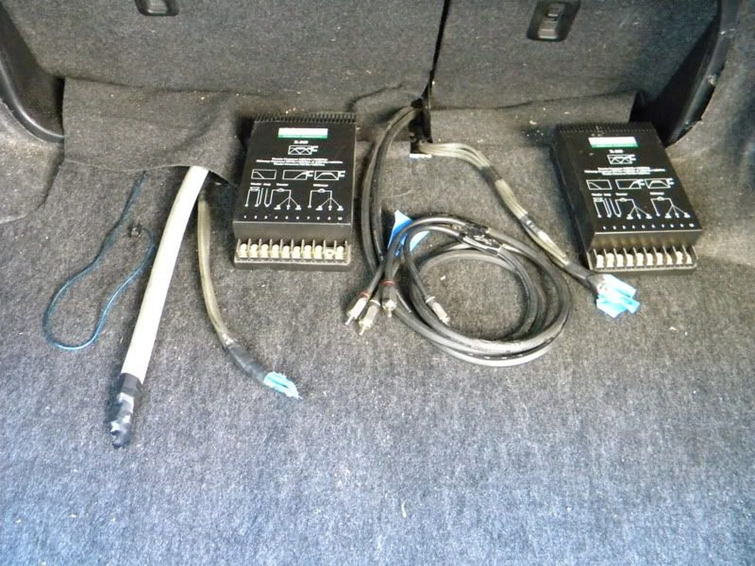
System pre-wired for amp hook-up with 1/0 AWG Stinger Expert in trunk
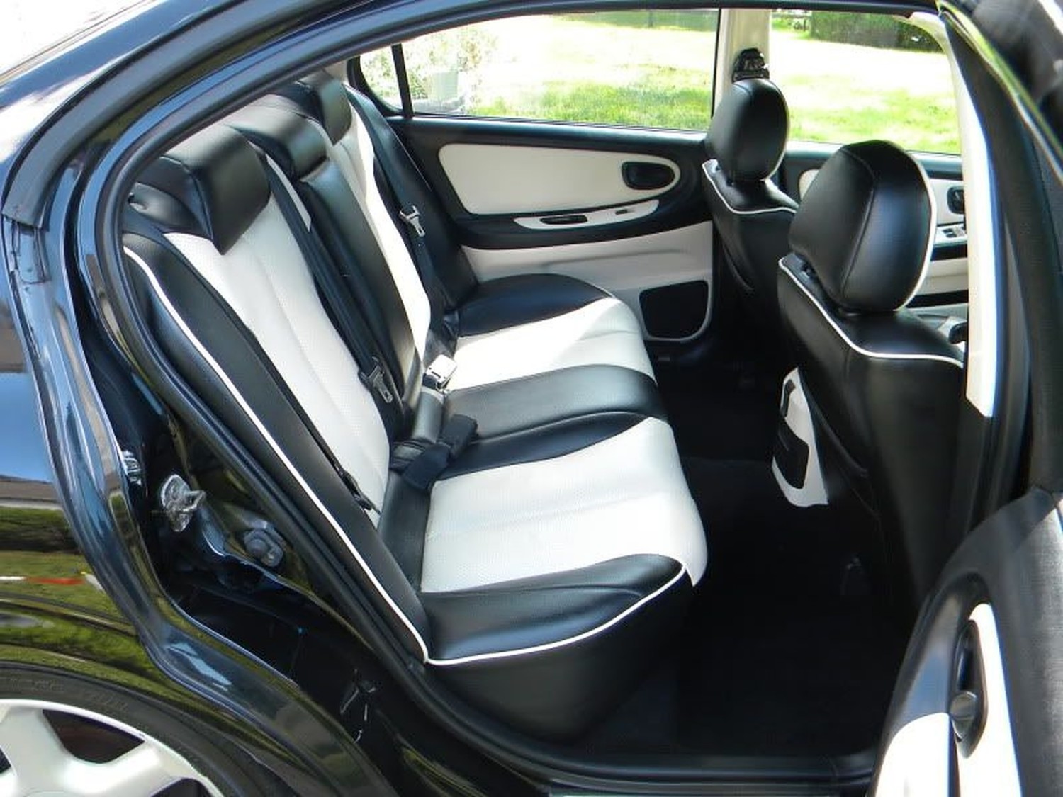
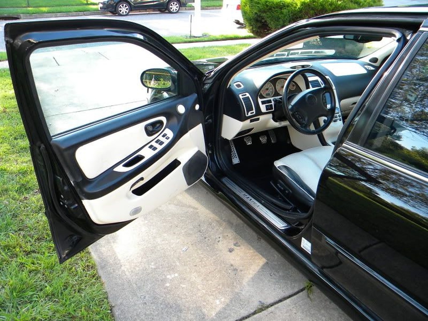
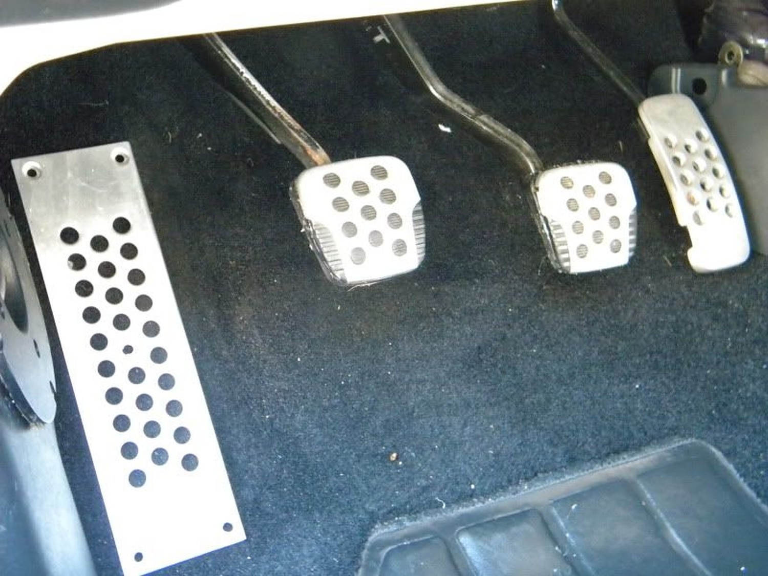
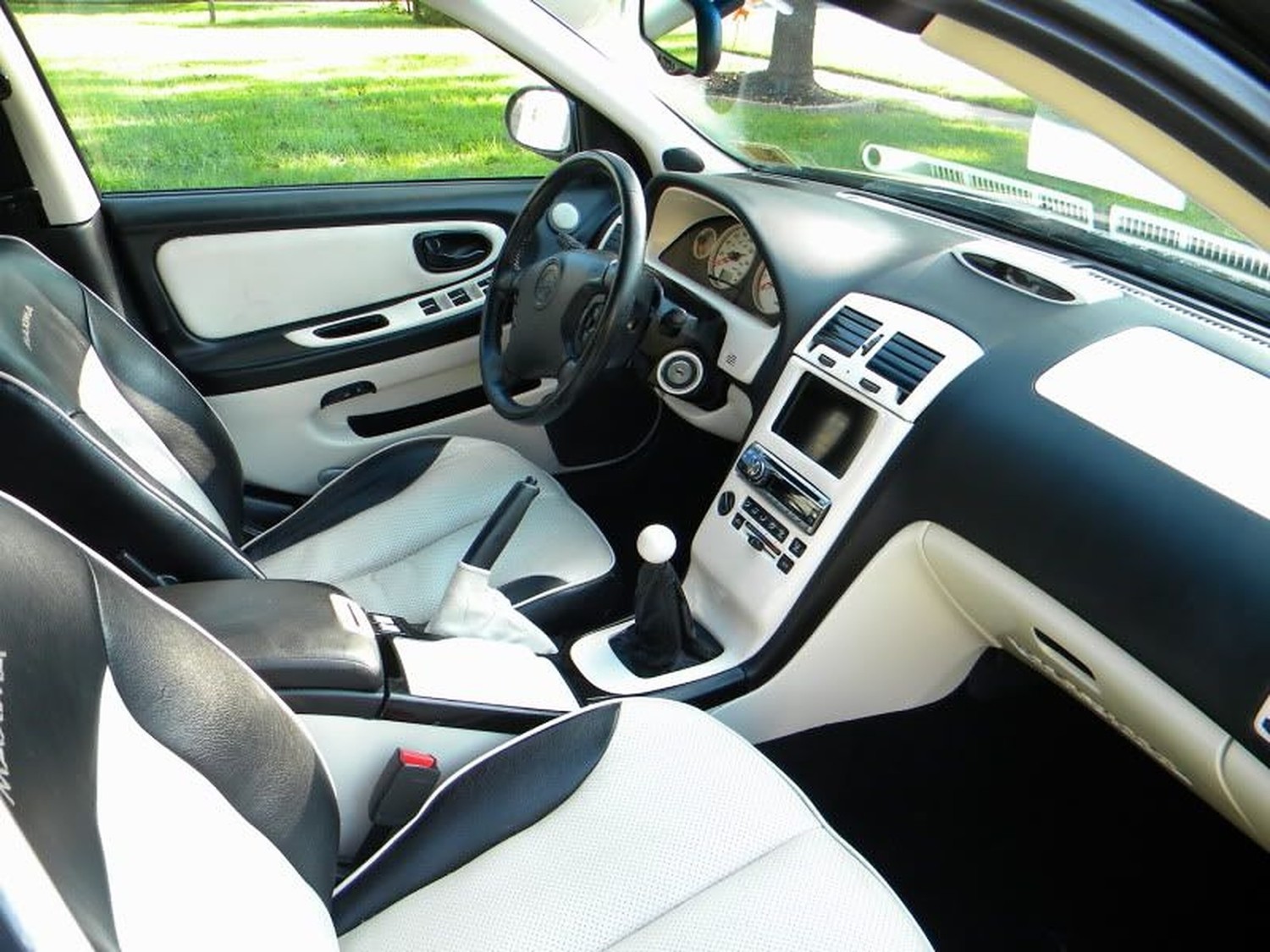
INTERIOR
Complete two-tone interior throughout
Custom leather seats
Fully customized interior (LEDs galore, custom switches)
EXTERIOR
Full Stillen lip kit
Full repaint in Black (spring 2009)
Street Scenes grille w/ original grille cut-out
![]()

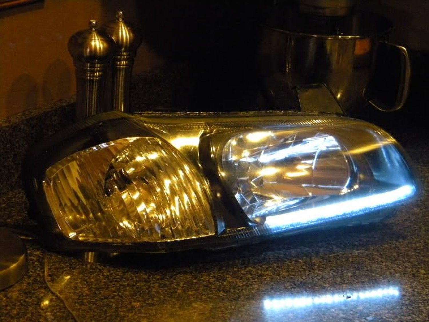
Member Credit: Metal Maxima
Alright, as my final HOW-TO on the .org, I am going to be detailing how one can black out your headlights and add the newly coveted Audi LED effect to your headlights. Without much adeiu, let’s begin!
ITEMS NEEDED:
STEP #1
Remove headlights. I am not going to detail this, there are two screws to remove that are exposed at the bumper level then just pull out…HARD.
STEP #2
You’re going to need to remove some hardware from the headlights before beginning. All rubber components, bulbs, and any screws that will come out. One universal item the bulbous thingie that was a beotch to remove in the previous step.
STEP #3
Obtain a flat baking sheet and a large towel. Wet the towel so it’s wet, but not dripping wet. Drape across the entire length of the sheet. TEST FIT THE SHEET WITH THE HEADLIGHT IN POSITION. Once you’re comfortable with the fit, preheat the oven to 250F. Place the headlight facing UP.
STEP #4
Bake for 10-12 minutes, ONE AT A TIME. Feel free to nervously pace the kitchen floor. *DING* That’s the sound of opportunity! Take your headlight out. I recommend using leather gloves, you’ll need the dexterity. Start by removing the two screws where the bulbous thing is…they are easier to remove once the adhesive is at working temp. Pry your headlight apart by using a flathead screwdriver to pry the mechanical attachment points open. Then pull…I only did 10 minutes and pulled…hard.
STEP #5
Remove the chrome components from the body. Here’s a shot of the only two screws for the 5th gen. The 5.5 gen will have more, sorry, I have limited pics of the 5.5gen. NOTE: Your lens portion will need to be warm for the 5th gen shroud to be removed; this allows proper expansion…believe me, it ain’t coming out otherwise.

You’re going to want to tape the chrome sections you want to retain. This is actually easier then it sounds. Use small pieces when going around the corners. TIP: Take the tape and slowly walk it across the contours…you will have 0 difficulties if you do so.

STEP #6
Paint using Duplicolor’s High Temp Engine Enamel. Do 3 coats; two light coats at about 12″ distance, very quickly. Do a third “wet” coat; you can do multiple light coats, but I’ve used close to 100 cans of spray, so I have an unfortunate familiarity with how it behaves. Allow 2 hours cure time, then peel away.


STEP #7
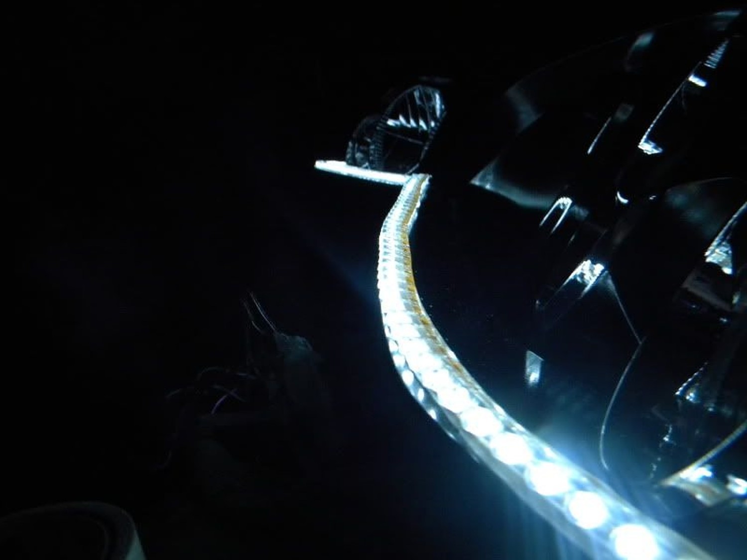
Cut your LED strip to size and attach it using the double-sided tape included. One the 5th gen, you’ll use 21 LEDs. The 5.5 gen is considerably more, just cut to size. NOTE: The array on the strip is in denominations of 3, so you must have a multiple of 3 in order for the full length to light!!! (i.e. 36, 33, 30, etc.)
STEP #8
Drill a small hole to allow for wire passage…I did mine as seen here on the 5th gen…I recommend going toward the turn signal as it is less readily seen below:

STEP #9
Now this is what I consider to be the hardest step. In order to properly reseal, we need to reuse the existing sealant. SO, back in the oven we go…ONLY PLACING THE LENS AND BODY IN THE OVEN. Do so at 250F for 10 minutes. You’re going to want to leave the body face up as the channels will likely contain the largest portion of sealant. Remove when the adhesive is glossy, meaning it’s at working temp.

STEP #10
While everything is hot, QUICKLY reassemble. Be confident, you can do it. You’ll need to do this for the proper seal. Push the body and lens together, making sure the mechanical tabs properly latch. Route the wire behind the lens shroud, you can drill your own hole or use the vent line aperture.
STEP #11
*WHEW*, ok, so you got the lenses probably 80% sealed. Time for some GOOP! Add some extra sealant, we’ve done all this work and don’t want to blow it now.

STEP #12
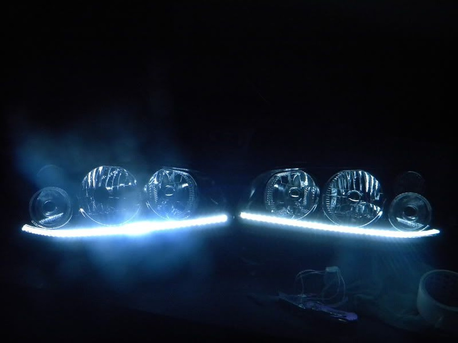
FIRE IT UP! Test with a 9V to enjoy the awesome effect. These things are BRIGHT!

![]()

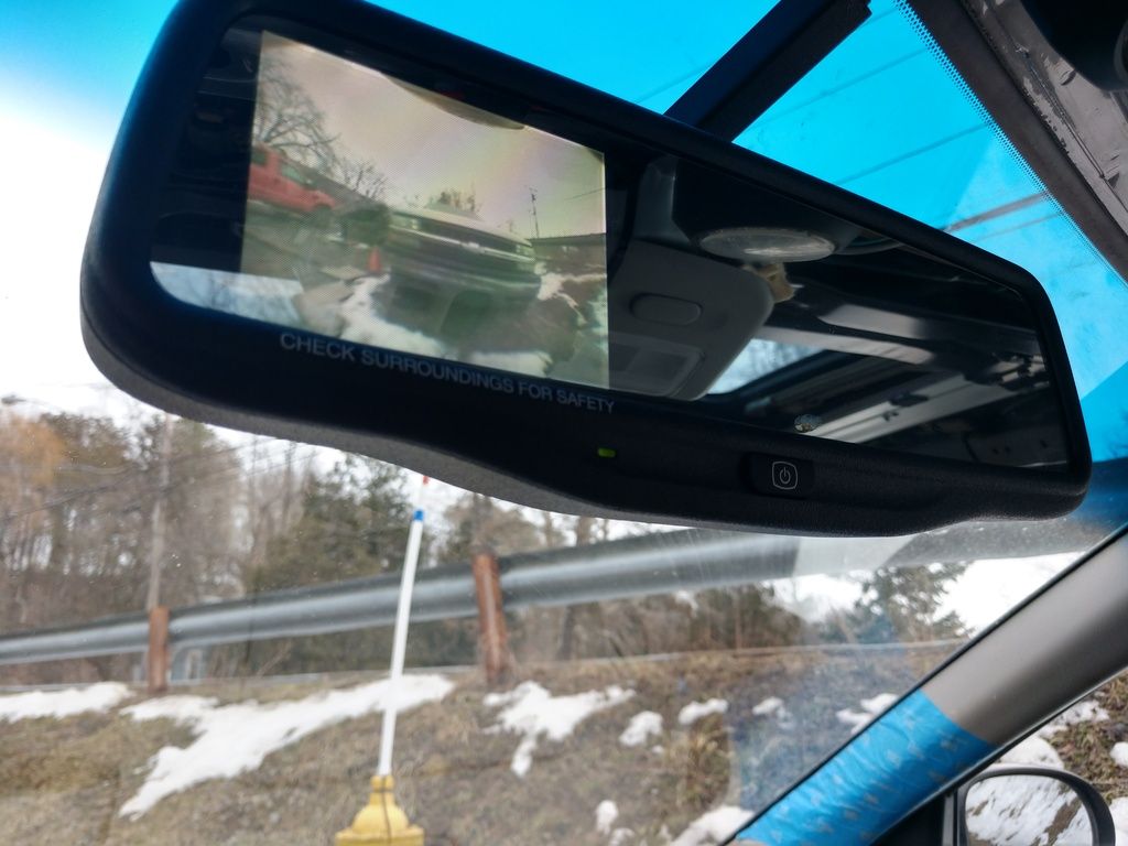
Member Credit: Theslaking
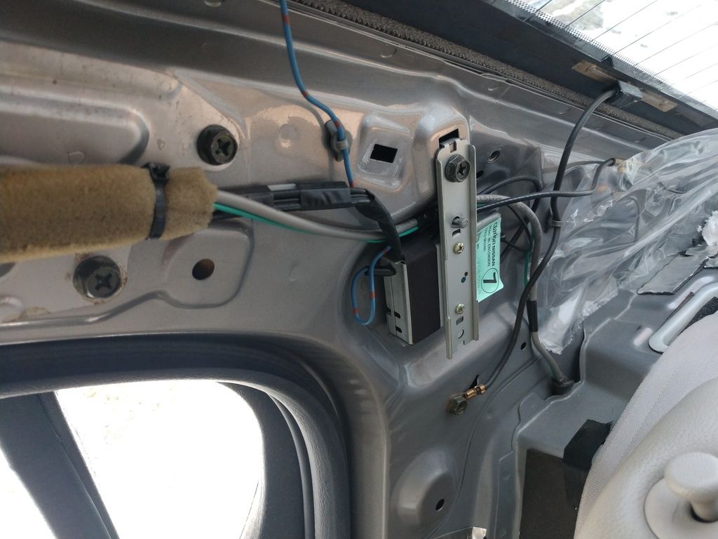
Grabbed a Nissan mirror with LCD from an 09+ Rogue. It was as simple as running wires in a vehicle I already had gutted. At first, I tapped into power upfront from the mirror but that caused too much of a delay with the camera turn on. So I just grabbed it in the back.
Power for the LCD still came from the original harness
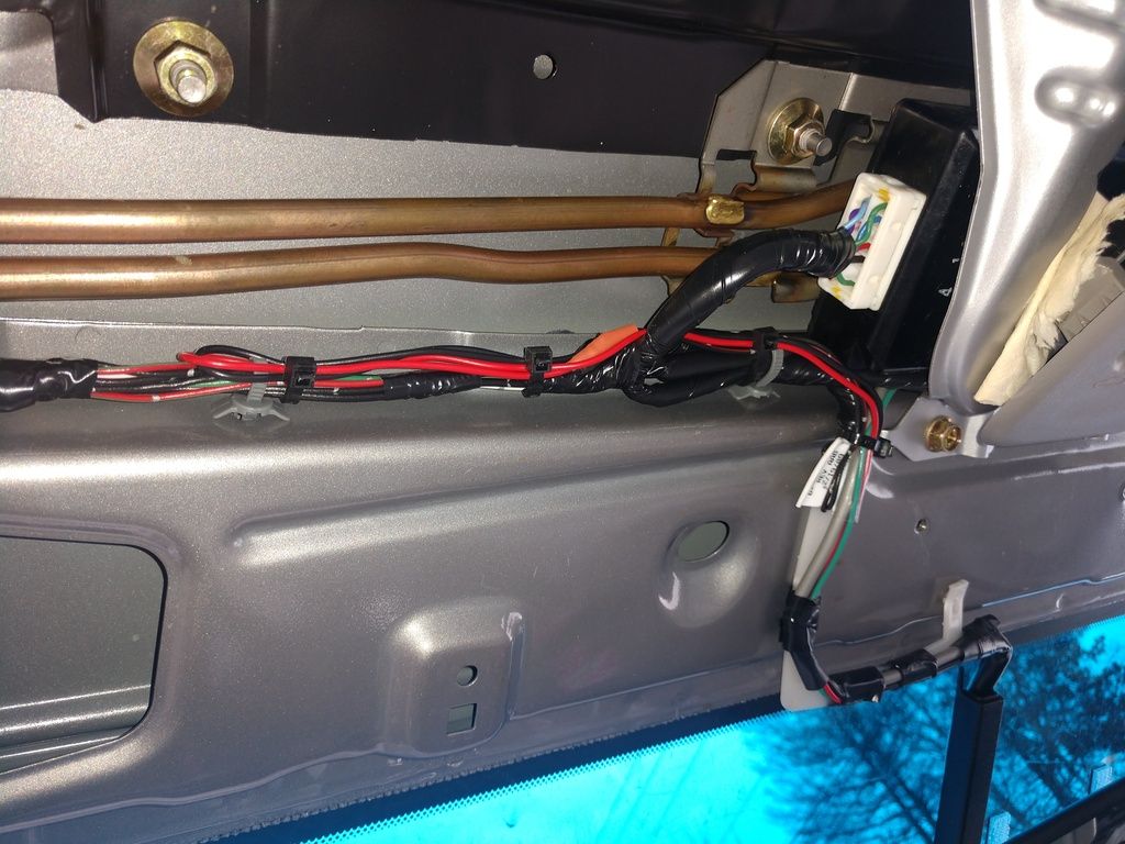
Ran the wires to the back. You can see the cut camera power wires
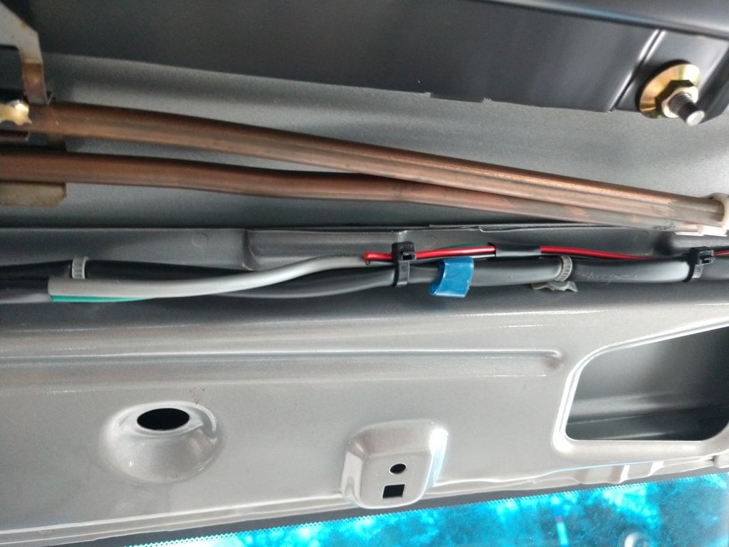
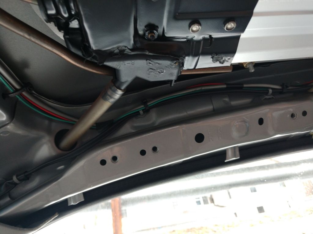
Down into the trunk. Put some Ensolite around the wires to prevent rubbing.
Into the factory loom and through the trunk lid.
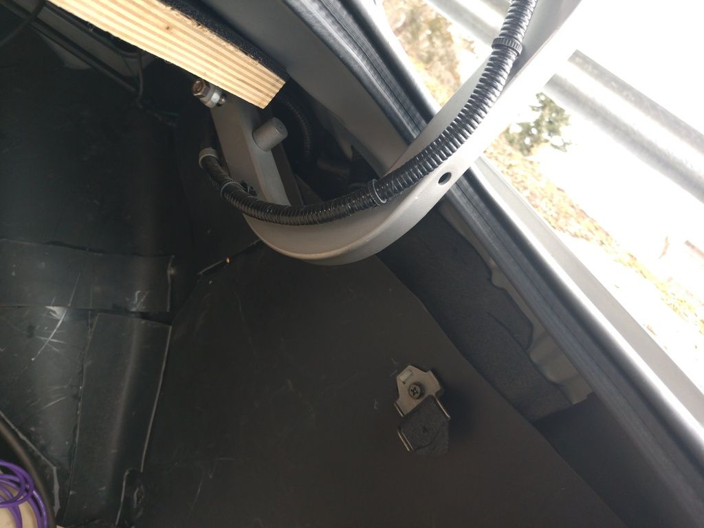
Drilled a hole in the plastic popped in a grommet
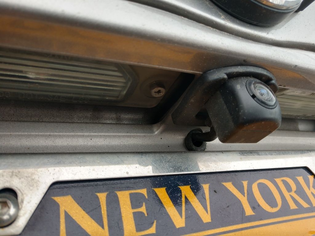
Finished look.
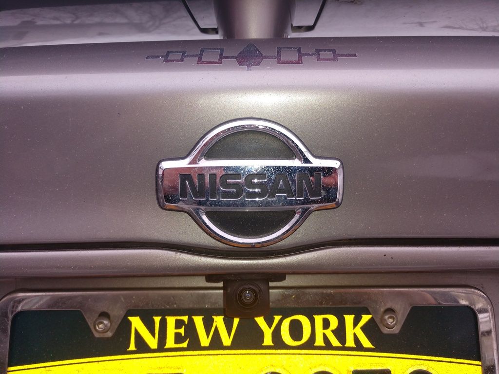
Screen showing old reliable!
![]()


