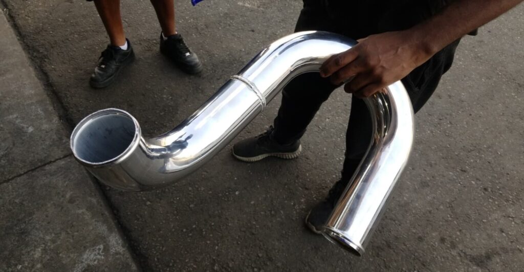
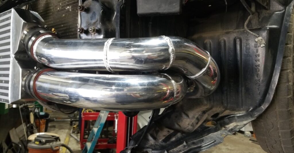
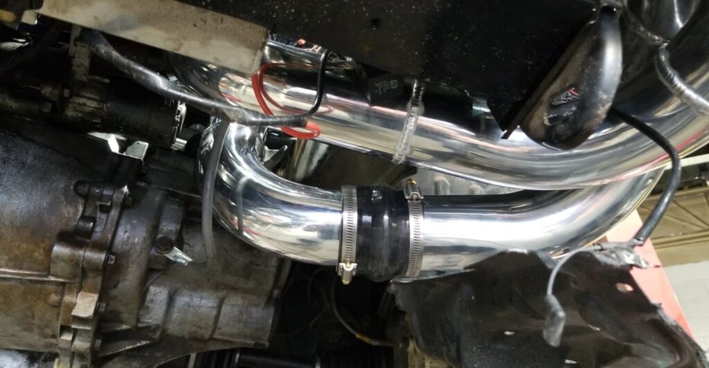
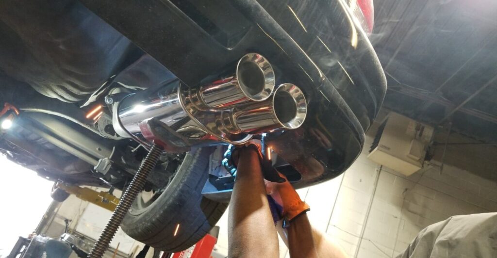
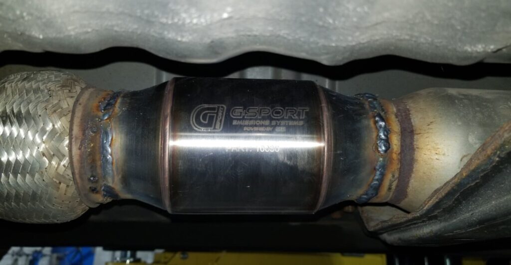
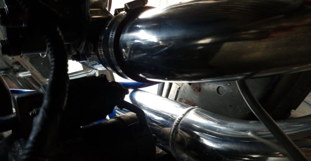
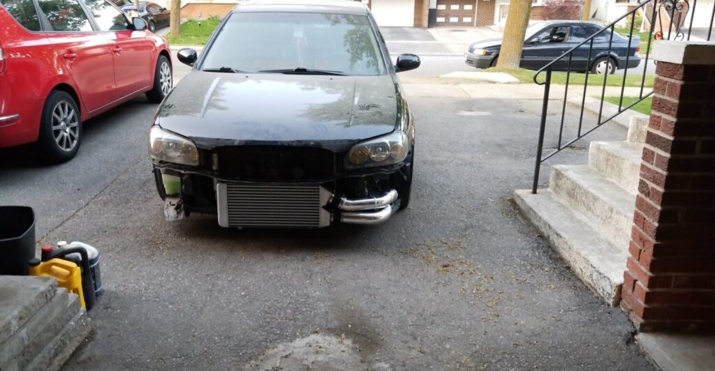
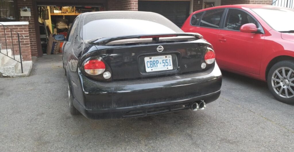
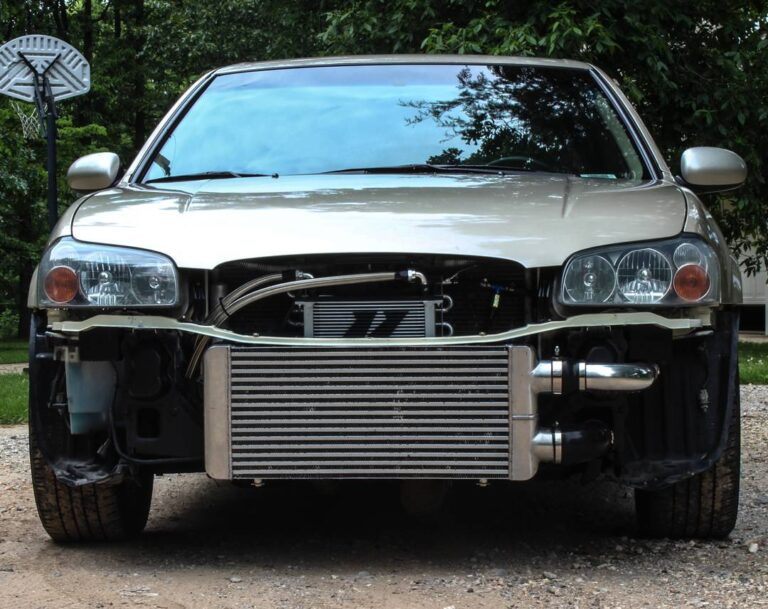
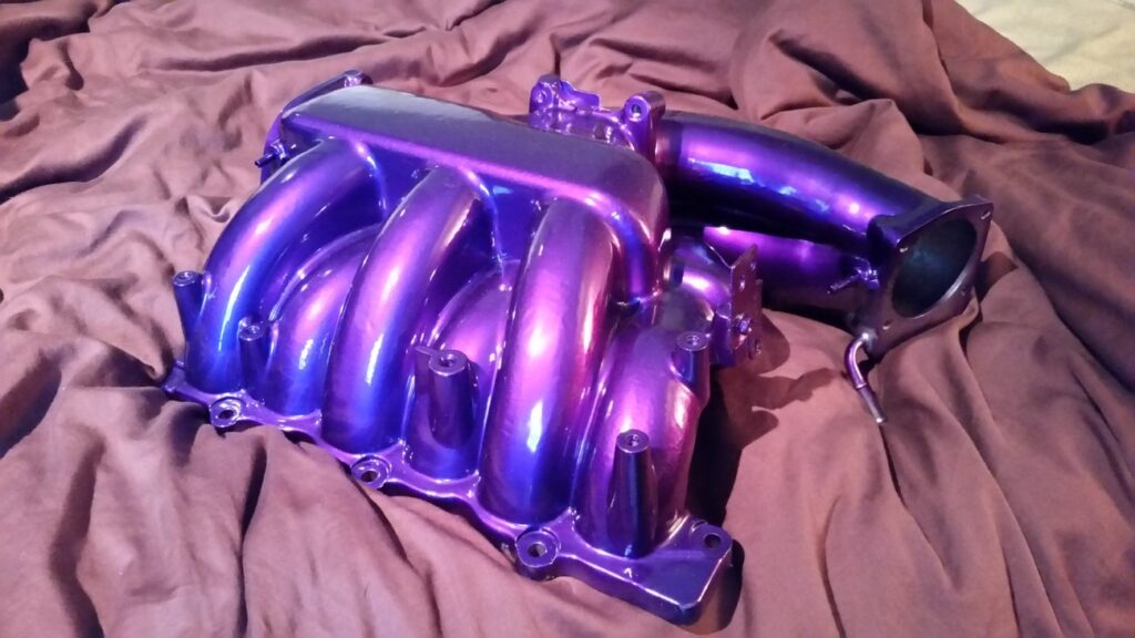
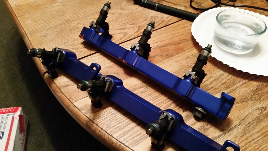
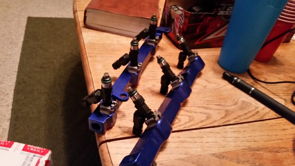
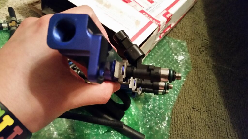
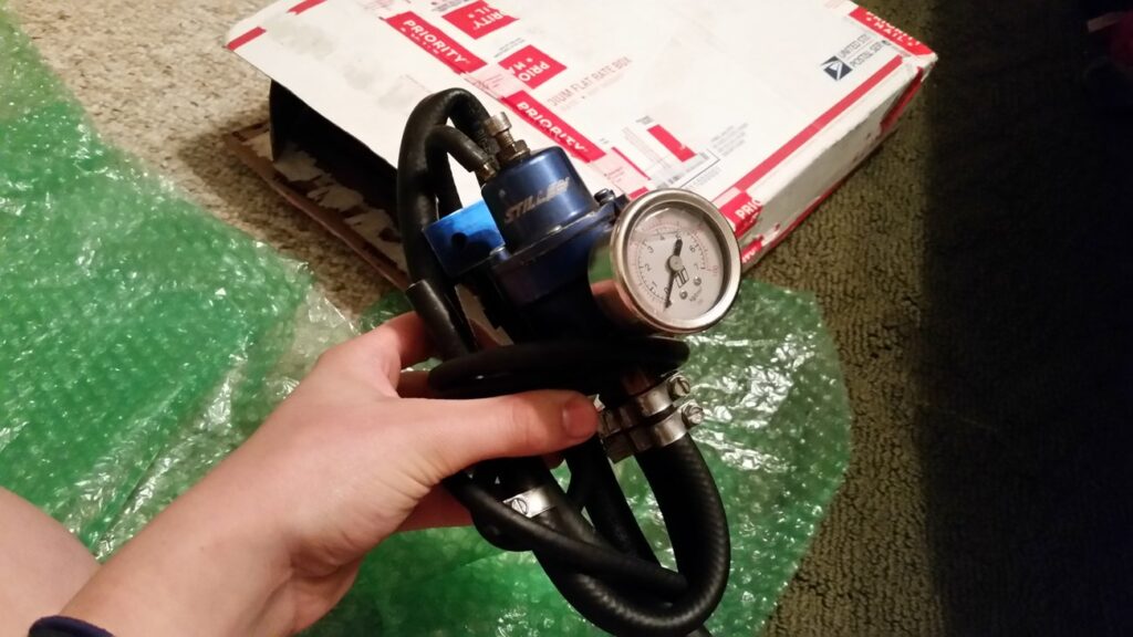
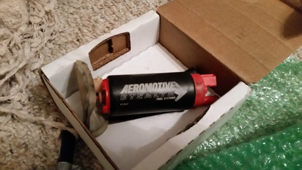
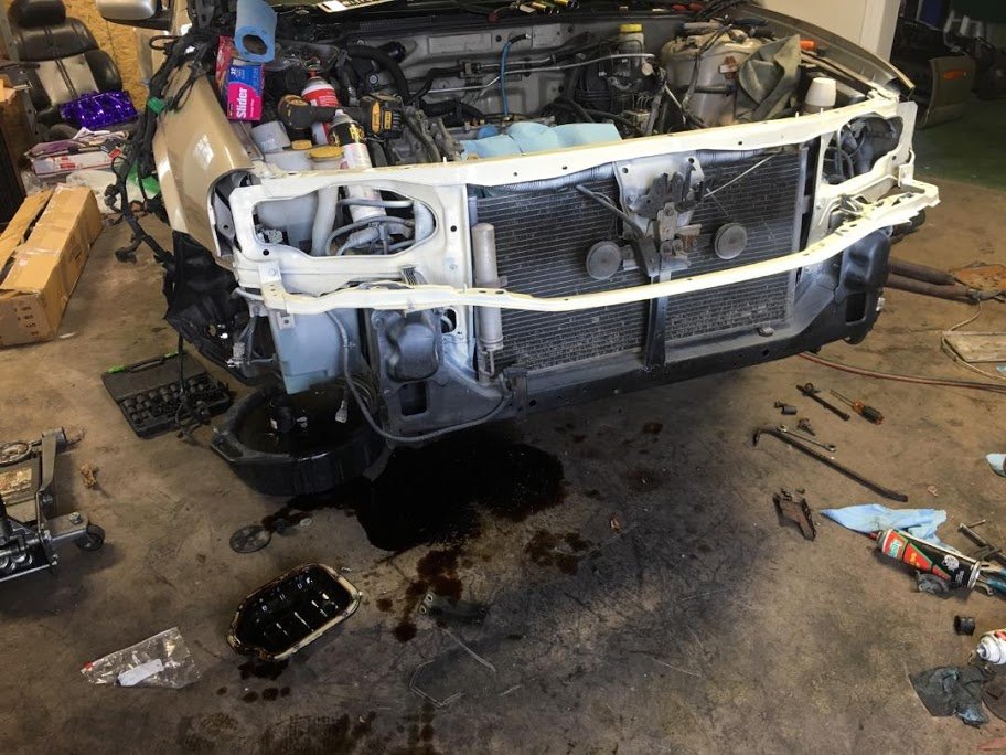
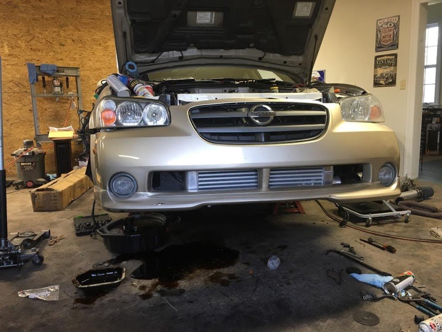
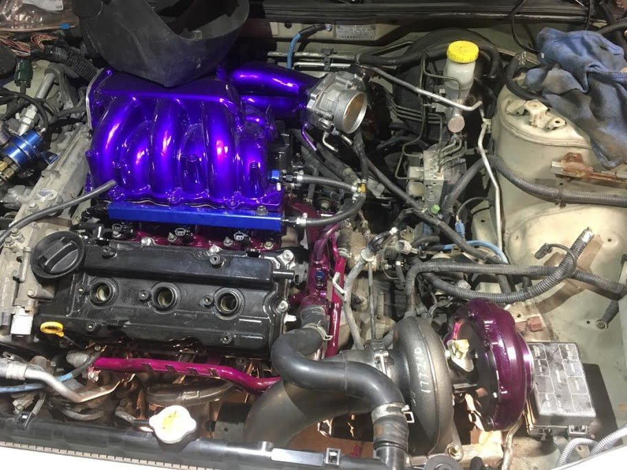
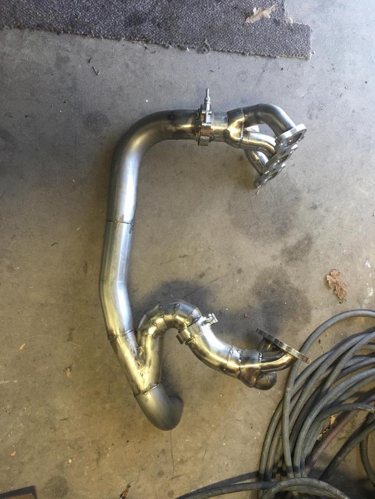
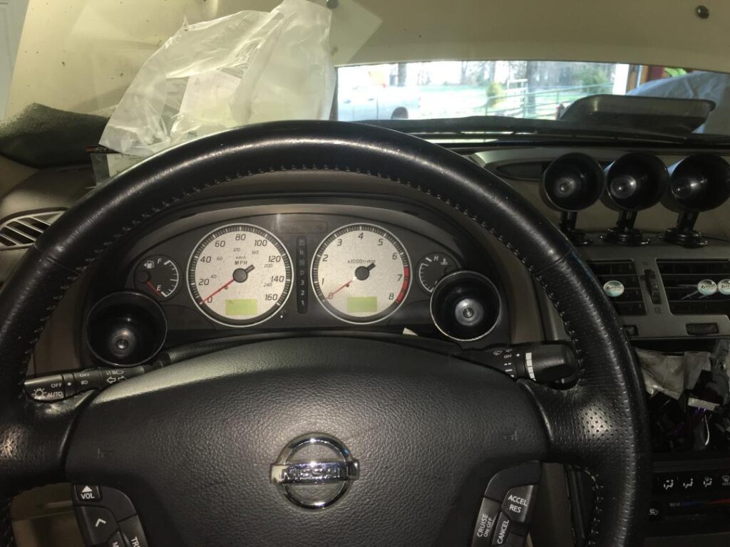
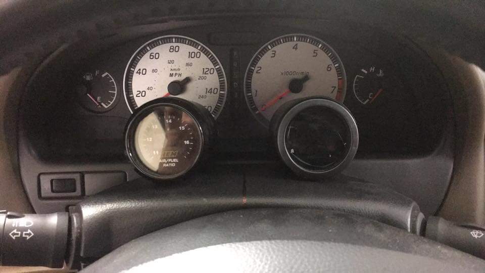
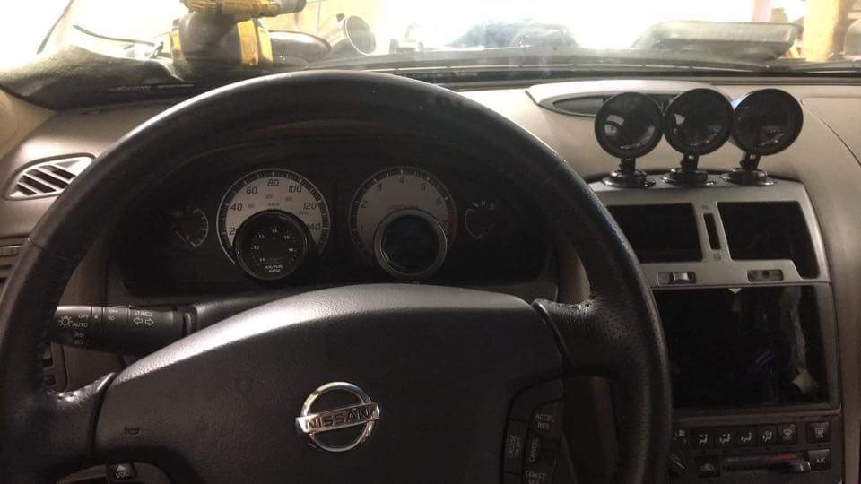
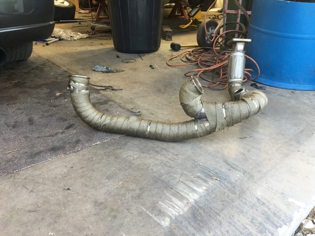
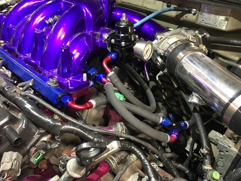
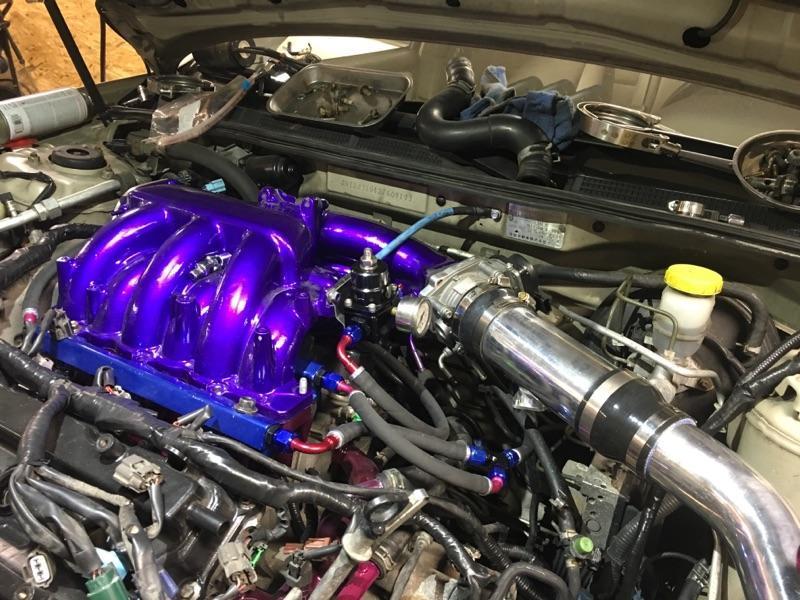
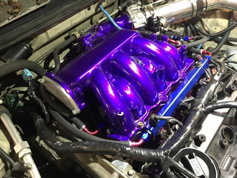
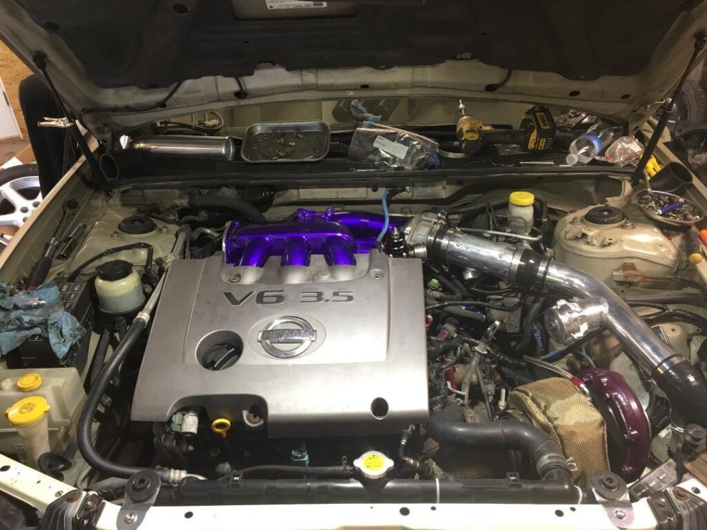
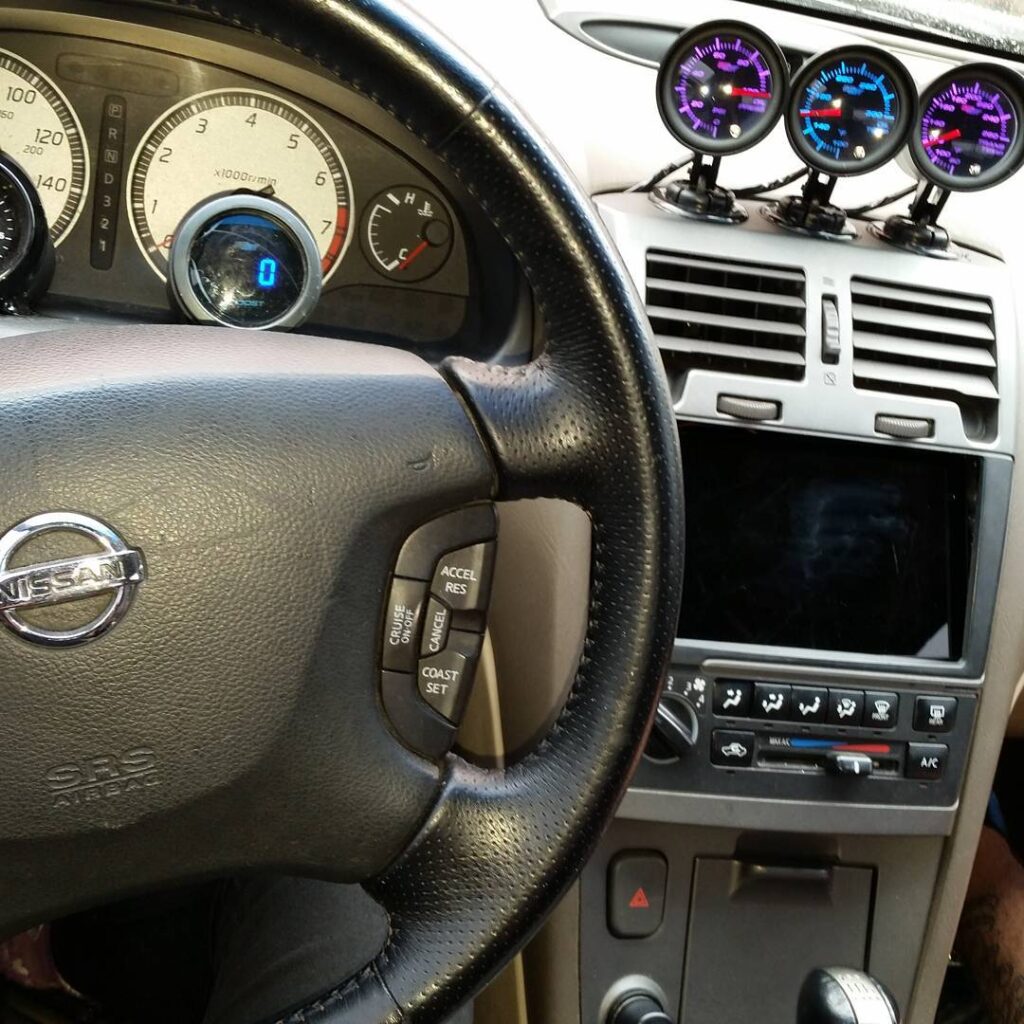
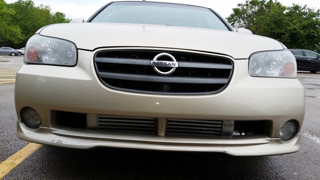
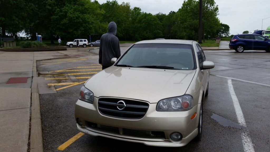
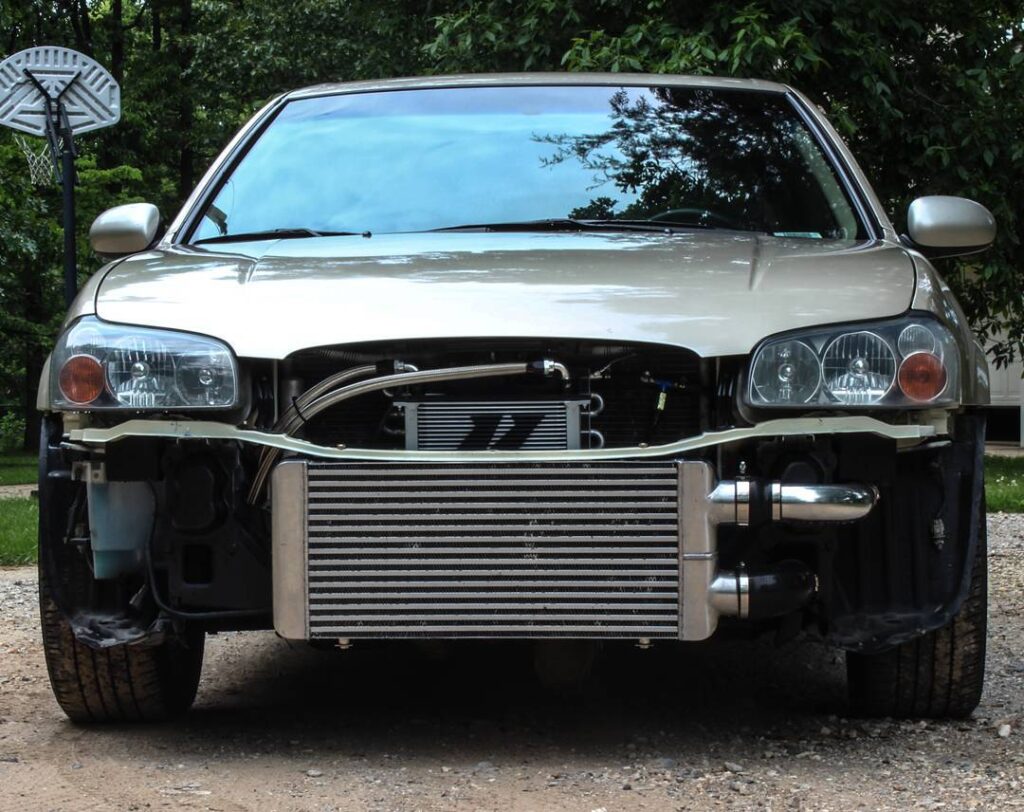
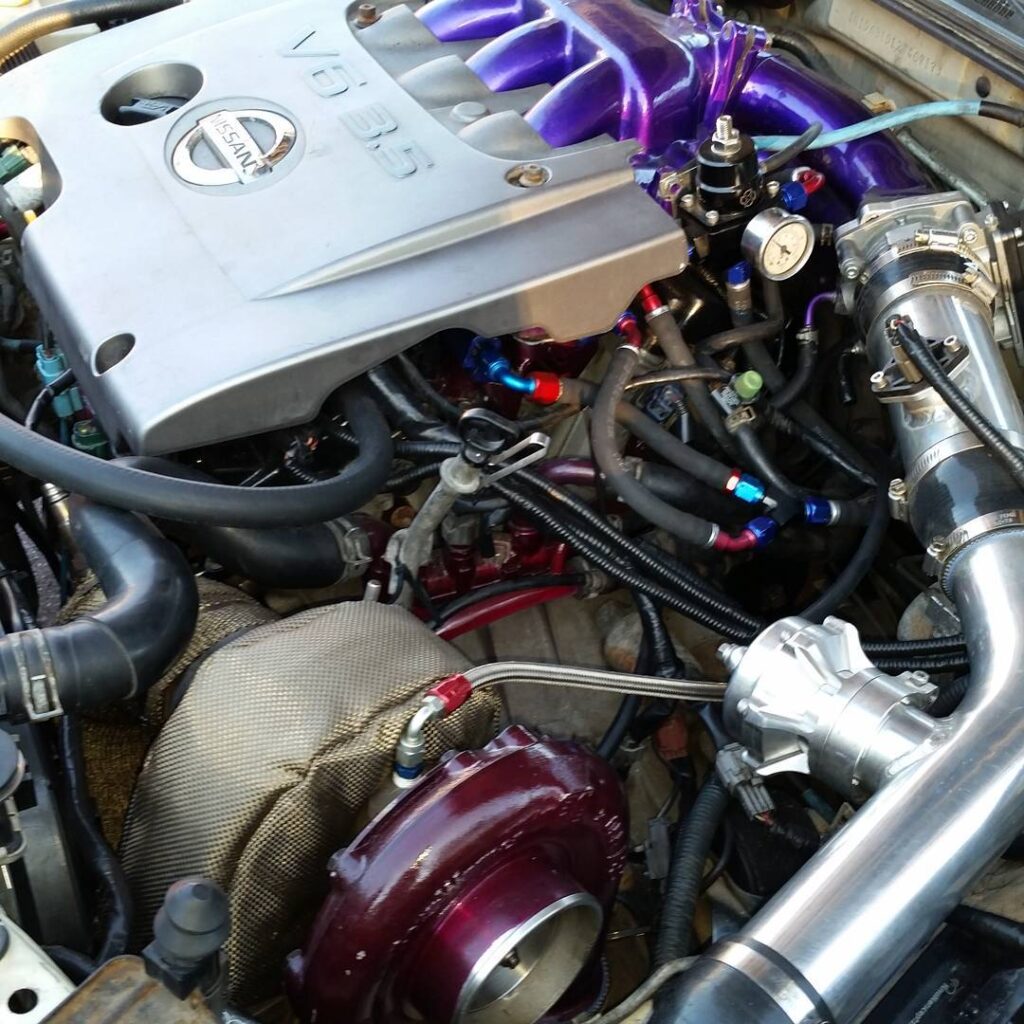
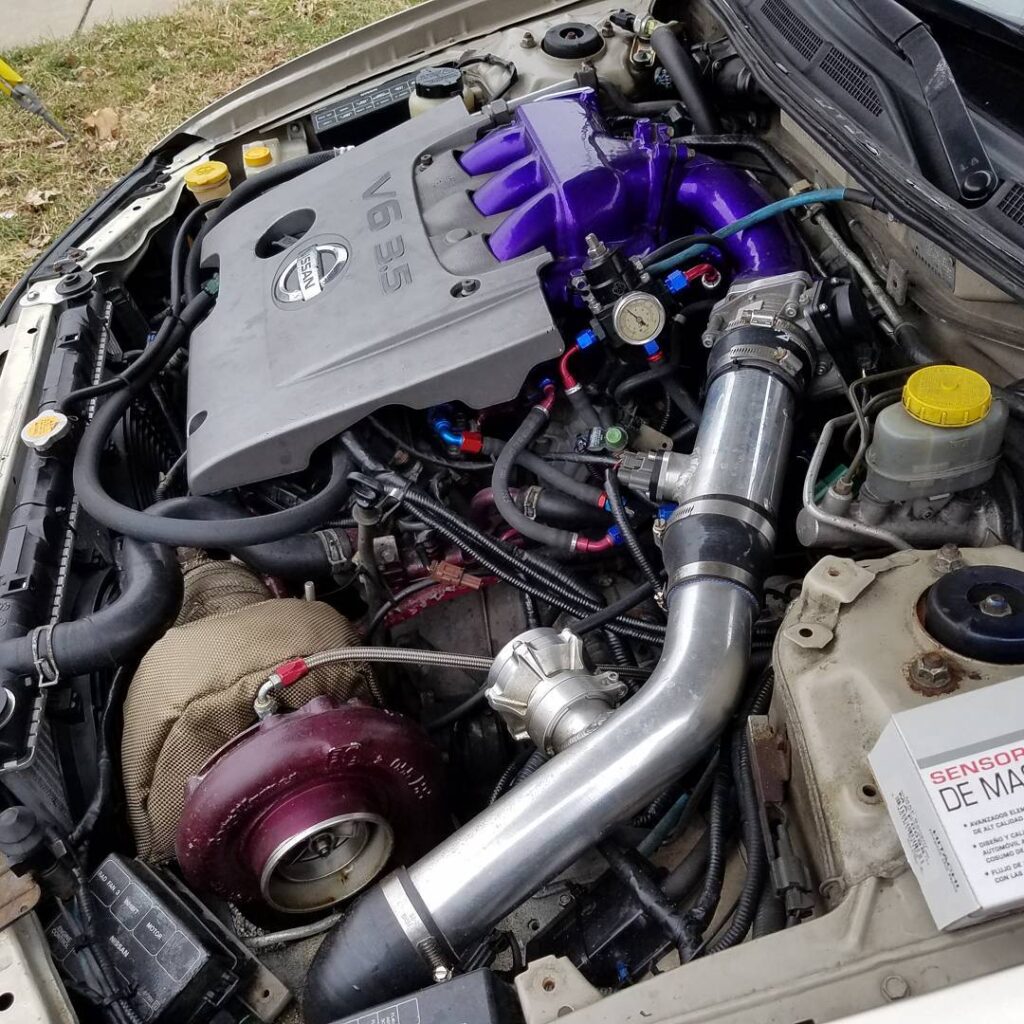
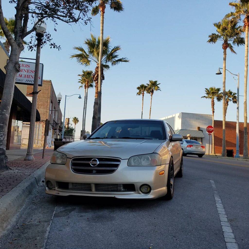
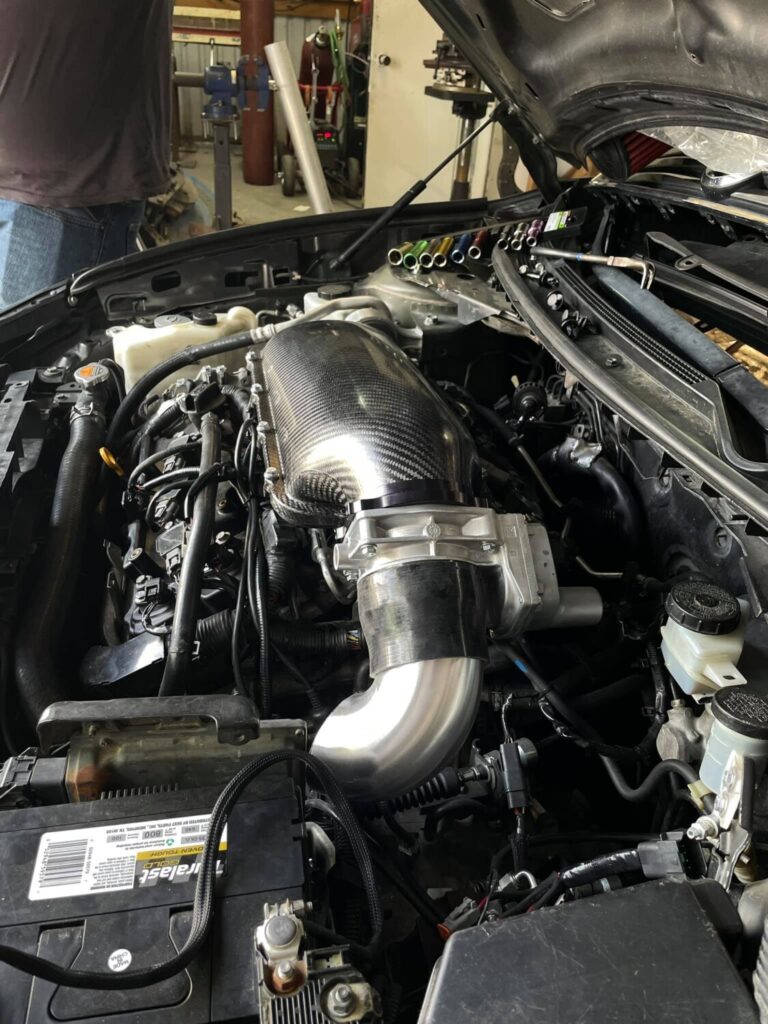
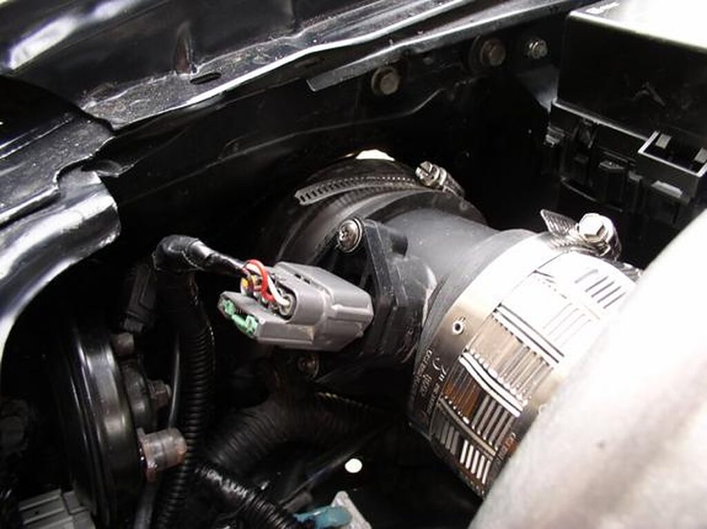
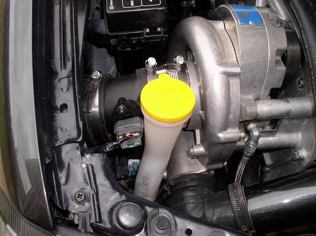
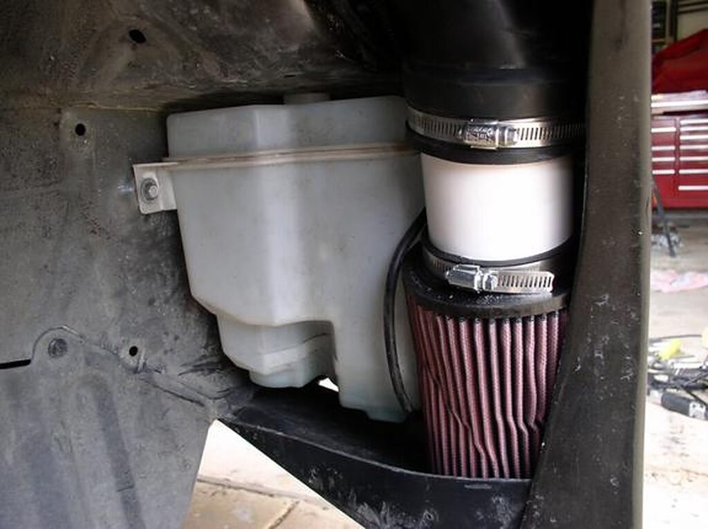
These are high-quality parts and services from a reputable member. We’re thankful that after all these years we have someone still making these. Not to mention he is easy to work with and ships fast.
I collected parts for both 00vi setup options. 4th gen LIM setup and all 5th gen LIM setup. Both of them would have used a 4th gen IACV and adapter. I am going with 5th gen lower because I decided the UIM was designed for the 5th gen lower, and I don’t mind tuning it when using the 5th gen fuel rails.
MY Swap Project:
5th gen Upper intake manifold (w/ mounting hardware, throttle cable bracket and PCV hard lines)
5th gen Lower intake manifold
5th gen fuel rail, injectors, NO adapter. (i used the existing line/barb and didn’t need a adapter)
5th gen Throttle Body
5th gen Rear valve cover
5th gen Rear Coil packs
IACV Adapter
4th gen IACV
Apexi VAFC2 (for tuning and Activation point)
Brass elbows, All threaded 1/4″. Barbs = (2) 3/8″ for Brake booster and EVAP and (1) 1/2″ for IACV)
Prepping the UIM
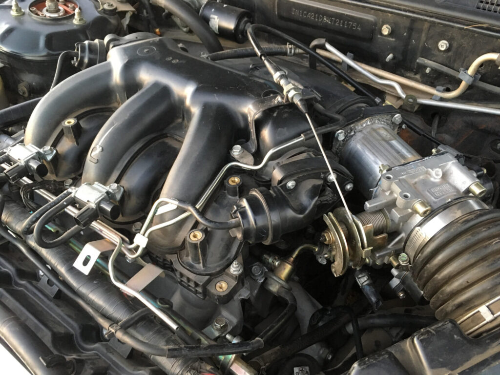
If you were like me, your junkyard/delivery man wasn’t too friendly with the UIM. As you can see my first UIM has the majority of nipples broken. Good thing we they’re inadequate for our 4th gen vacuum lines and we need to replace them anyway…
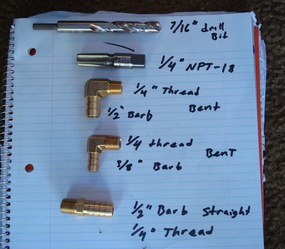
Here is what I will be using.
Materials: From top to bottom of the picture
7/16″ drill bit
1/4″ NPT-18 tap (available for sale, apparently my old man stocked up back in the day. They’re new and i have
/4″, 3/8″, and 1/2″)
Brass elbows All threaded 1/4″
Barbs vary from:
(2) 3/8″ 90 degree elbows for Brake booster and EVAP
(1) 1/2″ 90 degree elbows for IACV
Note: Ignore the Straight brass fitting in the picture. Didnt use it. 90 degree bent elbows work best. I used two 3/8″ x 1/4″ elbows and one 1/2″ x 1/4 elbow.
The straight 1/2″ barb is for the IACV adapter.
Lets start with the EVAP line located on TOP of the UIM where the Throttle body bolts up. Number (4) on the Diagram.
Damaged tower but still has plenty of meat to work with. First step, drill it out using a smaller 3/8″ drill bit, and move up to a 7/16″ bit to reduce stress. The 1/4 NPT-18 tap requires a 7/16″ hole.
Note: Either this plastic material is super fragile or my tap was razor sharp, but it cut through like butter. Make sure you know how deep your tap has gone so you don’t accidentally ruin your threads by over-turning it.
Result. Make sure you use some tweezers to pluck off excess plastic and prevent it from getting sucked in to your car later. Once its all clean, insert your 3/8″ barb x 1/4″ threaded brass fitting here, and your done. I also used RED permanent loctite (thread lock) to seal it up real good. You will probably want to use some RTV instead of loctite. I didnt, but i will if i encounter any leaks during the install.
Next, the brake booster line. Number (1) in the diagram.. Cut the existing nipple flush with the wall of the manifold and drill using 7/16″ bit. Careful, don’t go too deep, not a lot of meat in there, and you’ll quickly hit a wall inside the manifold. Just drill enough to widen the hole for tapping.
I then pulled out the rubber cap covering a small nipple underneath the brake booster nipple and cut it away enough to allow my brass fitting to screw in. Don’t cut it all the way to the wall like the brake booster nipple above it, leave some nipple there and cover it back up with the rubber cap along with some sealant. This will avoid the hassle of sealing it up with something like JB weld and getting sucked in.
Last, the IACV line, port 5 in the diagram. The brass elbow used is a 90 degree 1/2″ barb x 1/4″ threaded brass fitting that’s required to give enough air flow to the IACV adapter to prevent idle issues. I used a hacksaw to cut the tower behind the existing nipple. I then used my smaller 3/8″ drill bit to enlarge the hole, followed by 7/16″ drill bit. I then used my tap, and ended with the brass fitting and some loctite.
Edit: Don’t use Loctite. When it dries, it gets hard. Hard = cracking if you later want to re-position the nipple in a different angle. You dont want pieces of loctite in your engine. If i were to do it again i’d use High Temp RTV. Its orange and flexible when hard.
Note: These brass fittings are a ***** to get in. Once you’ve twisted beyond the strength of your hand, use a wrench to torque it in there.
Both fittings shown. The reason the top tower for the EVAP is still in tact is because i need to get another 90 degree 3/8 barbed elbow but the hardware store is closed. I WAS going to use the straight one but the hole that supplies that tower with vacuum is too small. I need to cut it off completely and enlarge the hole all the way through the manifold. Also, the process shown in the first drilling of the EVAP line was from my 2nd manifold which i will be selling. I prepped both manifolds for threads but only installed nipples in one.
Update: Top tower fitting installed
Painting 00vi Upper Manifold
Materials:
400-800 grit sand paper
Rubbing alcohol
Masking/scotch/painters tape
High Temp engine paint (gloss black)
Process:
Pretty simple: sand smooth, clean with rubbing alcohol, mask important areas with tape and paint.
Here I used some left over graphite colored wheel spray paint and “flaked” it from a distance to give it a diff. look.
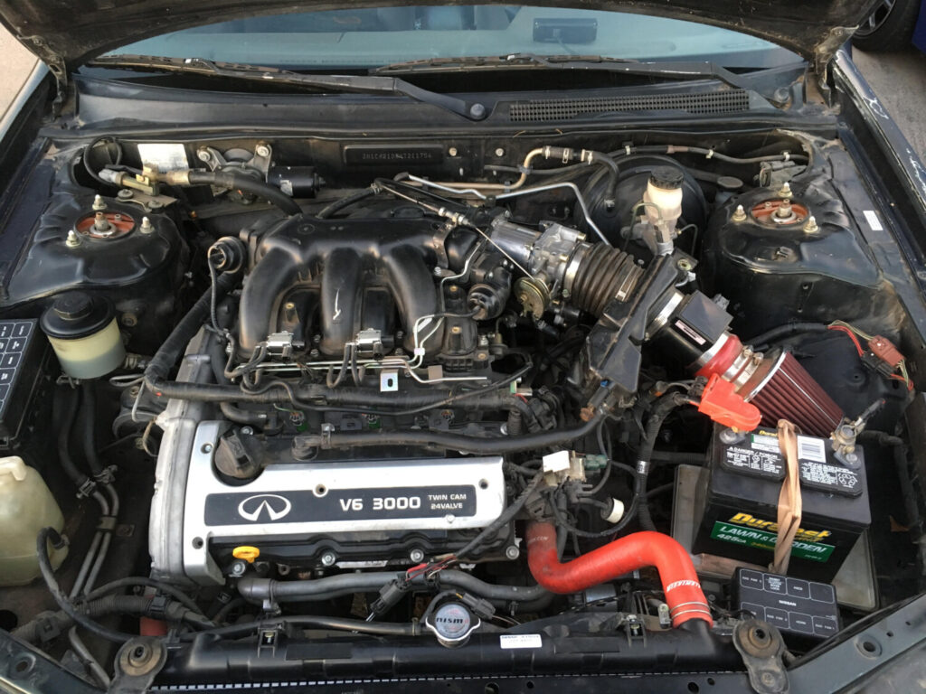
00vi Swap : The Removal I recommend getting your models Factory service Manual for reference.
If you’re attempting the 00vi swap you should be fairly familiar with what needs to be removed and how to remove them. I’ll try and go through the basics. Also, before you start, i recommend your protect your fenders with some type of cover between your knees/clothes and the paint. I used some brown wrapping paper and Painters tape to cover both fenders and areas pained near the engine bay. I also recommend you label your hoses and there they go. Use whatever it takes because no matter how good you think your memory is, you WILL lose track of dangling hoses.
A – Battery
B – Air Box
C – Mass Air Flow Sensor MAF (Handle with care…we don’t need more problems when troubleshooting your 00vi install)
D – Throttle Body – 4th Gen TB’s have a) Throttle Cables, b) Coolant lines (I plugged mine with bolts removed in the process to prevent spilling), c) Connectors (Throttle Position sensors, Brown and Black/Gray) that need to be removed.
E – Electrical log/Harness – This connects to: a) Coil Packs, b) EVAP valve c) EGR temp sensor, d) EGR unit itself, e) Throttle Position sensor. Remove these and the log can be bent out of the way towards passenger side of engine bay.
F – Upper Intake Manifold – Mine had 4 bolts up front towards bumper and 4(?) in the rear attached to mounting brackets. Stick your hand back there and familiarize yourself with the brackets and the number of bolts. Not 100% sure how many there are back there. UIM also has the throttle cables mounted to the bracket, loosen the cables and they slip off the bracket. If your 00vi didnt come with a bracket, avoid removing the cables and just remove the bracket itself and push/tape out of the way. The EVAP valve is also on top of the UIM, remove it and get it out of the way. Your PVC line will also be attached to the UIM, remove the vacuum hose. Behind the UIM, your EGR tube is attached, there are 2 bolts holding it. Under the EGR tube are 2 short coolant lines that run through the UIM. I didnt bother removing mine properly due to the tight space, i just took a knife to the hoses since I replaced the two EGR coolant lines and make a “UIM/Throttle Body coolant bypass”. Remember to note which one Runs coolant and which one Returns it, they lead back to the coolant log near the front Valve cover/ Knock sensor connector cable.
G – EVAP valve
H- Not visible in picture but this is where you Idle Air Control Valve is. (IACV)
(ignore the “stand alone” label)
Here is your EGR tube removal since you need to use the 5th gen EGR tube with the 5th gen Upper Intake Manifold. I used a Dremel and a cutting wheel to cut the stud tip off. This is necessary to remove the nut holding the EGR tube itself, since that brass looking tube is in the way. I’ve read you can also cut it using a hacksaw blade…without the handle. Might take a while though. Make sure you plug/cover your fuel lines before grinding away here to avoid any unwanted ignitions.
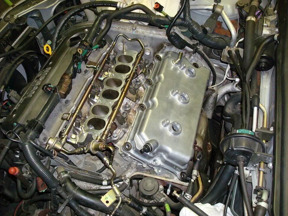
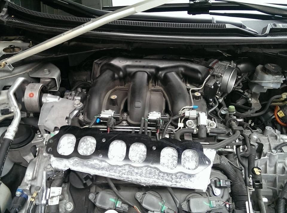
Rear valve cover and Lower Intake manifold
Pretty straight forward, unbolt and replace. Use new crush gaskets for the LIM and if your Valve cover gasket is still good, use some Ultra Black RTV. I failed to do so and had a oil leak, had to remove everything, clean the oil off the gasket/valve cover, and RTV the gasket into the valve cover grove, then RTV on the gasket to the head. For the LIM, i took my time torquing the bolts, little by little, starting from the middle, outward. Search for the torquing procedure on the org or in your Factory service manual. Same with Rear valve cover. Also, inspect your new rear valve cover’s rubber grommets. There’s four, 1- PCV, and 3 for spark plug tubes.
Fuel Lines:
Ignore the tags. (VAFC2 Vafc 2 VAFCII VAFC II )
I bought my Apexi VAFC2 used and it was missing the 20 gauge extension harness. The wires on the main unit itself are VERY fine, above 22 gauge, and would not be easy to work with when splicing into the ECU.
What I did was take a old Computer Power supply and use the 20 gauge wires as an extension/adapter for my splice connectors.
Materials:
-Splice connectors. Can be found at radio shack.
-Soldering iron / solder
-electrical tape
-Wire stripper
-Wire cutters
-Sacrificial Computer Power Supply Unit wires
-VAFC2 harness (the VAFC2 is inside the glove to protect it… )
-wet sponge (cleaning iron tip)
Note: If i could do it again, instead of cutting wires off the Power supply unit, i would have cut off an entire Power supply unit harness with connectors attached and used that as a removable connection to my VAFC2. The PSU clips would have been useful.
First, i started stripping ends of the PSU wire. If your lucky, you’ll find matching colors to your VAFC2 harness. I found all of them except for brown and pink. For brown i used Black, as it is a ground, and Orange for Pink.
To strip the super thin wires from the VAFC2 harness itself, i used a new razor blade and gently twisted it around the wire. I then bent the wire to expose the cut and pulled off the insulation with my finger nails. Use common sense on applying pressure on the blade.
My method of soldering is pretty amateurish but i don’t care. As long as you make a solid connection, any method works. I just twisted both ends of the wires and bent the tip back with pliers.
Followed by solder.
I then used electrical tape to seal the connections. Others will suggest heat shrink wrap but i couldn’t find any @ Home Depot, radio shack, or auto zone. The result.
Note: Maxima’s DO NOT use VAFC2 wires: ORANGE, LIGHT BLUE, and PURPLE. I covered each tip with electrical tape and then taped them all together and stuffed them back in the main insulation on the VAFC. See diagram in next post for wiring.
Before you do ANY of this, make sure you disconnect your Negative battery terminal before you work on splicing into the ECU.
Here we have the wiring. There are two power wires (red) and two ground wires (one black and one brown) required to function the VAFC2. Each set is spliced into the same Power or Ground in on the ECU harness and spaced apart 1cm or more. The MAF wire on the ECU harness must be CUT, not spliced. Once cut, the end still attached to the ECU CONNECTOR/CLIP is connected to the YELLOW wire on the VAFC2 harness. The other end of the MAF wire we cut is attached to the WHITE wire of the VAFC2 harness.
Refer to YOUR Maxima model’s Factory Service Manual for correct wire colors on the ECU harness. Wire listings can be found in section EC under ECM Terminals and Reference Value.
Note: I haven’t messed with the MAF wire yet because i need to get some plugs for the wiring. These plugs will allow the MAF wire to be reconnected to its original form easily should you choose to remove the VAFC2. Also it helps make a cleaner and secure install. I also avoided splicing into the Knock Sensor wire, apparently this caused some issues with the car starting and previous installers have avoided this part of the install. Please correct me if im wrong on this.
Edit: DO NOT use knock sensor wire. We dont need it. – per gtr_rider. Its not designed for our cars
Go to the Passenger side and remove the cover concealing the rear of the ECU/ECM. You will see a white plastic cover over the wire harness. Use a 10mm socket wrench to remove the bolt and then proceed to remove the harness/clip from the ECU. Once off, give the harness a bit of a tug to expose more working space. Nothing to drastic, just enough to get an extra inch or two. Remove the white/clear plastic cover from the harness clip using a flat head screw driver. Now we can begin searching for our desired wires.
Splice connectors are pretty self explanatory.
Don’t ask me how im going to get the plastic cover from the ECU harness back on, i probably wont.
Plug ECU harness back in, bolt it on, and reconnect your negative battery terminal. Turn key to ON position and if all connections are correct, enjoy your working VAFC2. I did it on my first try.
Note: The Yellowand white wire above are for the MAF wire. I didn’t get to this yet as i need some plug connectors. The Blue wire i believe is for a Wideband 02 sensor for tuning. Don’t have this yet, so also not used. The Orange wire you see is actually routed to the PINK wire on the VAFC2. PINK wire is used to send the 12v signal to the VIAS to activate the 00vi.
All systems go. At first my RPM signal wasnt working. I went back and made sure the tachmeter connecter was fully spliced using a pair of pliers. It did the trick and everything functions correctly.
I finally got some more brass fittings from ebay. My local source ran out of them and they were getting a bit pricey. (5$ a elbow). I got (6) 3/8 x 1/4 elbow fittings for about 10$.
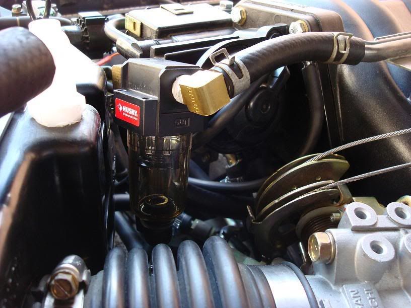
Why six? Well, i need two for the 2nd 00vi im going to sell, 2 for my oil catch can, and 1 for my current 00vi, which i painted in above posts.
-5th gen Upper intake manifold
-5th gen Lower intake manifold
-5th gen fuel rail w/Damper and FPR, No adapter.
-5th gen FBJC100 290cc injectors
-5th gen Throttle Body
-5th gen Rear valve cover
-5th gen Rear Coil packs
-5th gen Snorkel & Air box modified to fit 4th gen MAF
-IACV Adapter
-4th gen Idle Air Control Valve
-Apexi VAFC2
-Husky (Home Depot) Oil Catch Can
Well, if you’re here, you are probably experiencing some trouble because the TPS is not a regular maintenance item! Unfortunately, TPS failure seems rather common. It’s happened to me, and I see it in one to two other Maxima enthusiasts a year. Heck when Edmunds.com was evaluating the new 2K Max, they had problems with the TPS. And the car was brand-spanking new!
WHAT IS THE TPS?
The throttle position sensor is a potentiometer – a variable resistor. The ECU sends the TPS a 5V signal. Depending on the position of the throttle, the TPS will send back to the ECU a voltage proportional to how open the throttle is.
Here is a pic of the TPS.
This is the back. Notice the metal bracket that connects to the throttle body. This bracket is rotated by the throttle to change the TPS’s internal resistance.
Symptoms: The most obvious is if the TPS just up and dies. You’ll get a check engine light and the 0403 trouble code. (Trouble codes will be covered at a later date). However, if the TPS is still gasping its last few breaths, you won’t necessarily get the light. But you will get inexplicable, “spontaneous” drops in RPMs. It’s most pronounced when you are at idle or the engine is coasting to idle after disengaging the clutch. I have yet to see someone tell of problems when the car was moving/accelerating.
TROUBLESHOOTING:
Here is the TPS in the engine bay (red arrow).
You want to pull out the connector away from you (yellow arrow). Do this when the engine is OFF.
You will then expose the pins on the connector.
1. Connect the positive lead of your multimeter (voltage checker) to pin 1.
2. Then connect the negative lead to a ground in the engine bay.
3. Turn your key to the ON position (Do NOT start the car)
4. You should see about 5 volts on the multimeter, indicating the ECU is sending the proper signal.
5. Reconnect the harness to the TPS and start the car.
6. Warm up the car. (This is because heat affects resistance)
7. When warm, turn the engine off, and put the ignition switch to OFF.
8. Connect your meter to pins 2 & 3.
9. With the throttle completely closed (foot off the gas pedal), you should read about 500 ohms of resistance.
10. Start pushing on the gas pedal – resistance should rise. When the gas is fully depressed (wide open throttle), the resistance should be about 4000 ohms.
11. If you are slightly off, you can still adjust the TPS to compensate.
12. Notice that the holes that the screws go into on the TPS are slotted, giving you some clearance. Loosen the screws so that you can turn the TPS in place. If you can twist the TPS so that the values are correct for the different throttle positions, retighten the screws – you’re done.
13. Otherwise, you are out of luck. Time to pick up a new TPS.
A new TPS will cost about $60-$70. Just unscrew the two screws holding the old TPS and put the new one in and adjust until the resistances are right. Then, tighten down the screws. (Yes, the 2nd screw on the other side not shown in the pic is a pain to unscrew) (And yes, these are not the OEM screws. I galled the OEM screws unscrewing them out. These screws are bought from “Home Depot Motorsports” hehe.
Here are the steps involved in converting to a 70mm Pathfinder throttle body:
1. Make or purchase adapter plate,
2. When you first do a trial fitting of the adapter plate to the intake manifold, you will see that the 70mm opening is considerably larger than the bore of the intake manifold. I got my high speed drill (cordless drills are too slow) and a bag of coarse grit 2” sanding drums and started opening up the intake to match. First scribe or mark the 70mm diameter of the adapter plate bore onto the mating surface of the intake. Then start removing material. I did it with the intake manifold removed from the engine. If you do it on the engine, stuff several rags down the throat to keep aluminum dust out of the engine and then use a shop vac to suck all the dust up. It’s a good idea to have the shop vac running with the nozzle fixed in place at the grinding area so that the dust immediately gets sucked away. Note that the outer surface of the intake necks down several millimeters just beyond the mating surface. For that reason I was not comfortable increasing the bore all the way out to 70mm in that region, rather I tapered down to a 68mm bore to keep from breaking through the wall of the intake. I removed material for about 3-4 inches into the intake, and followed up with a nice polishing job with a Dremel. I wish I had a picture to show you, it was very pretty.
3. If you bought a TB that had the Pathfinder IAC and coolant passageway attached, you will have to remove them because there is not enough space beneath the TB for the IAC stuff.
4. You will have to make a plate that bolts to the bottom of the TB to seal it off, otherwise you will have a massive vacuum leak. See the attached jpg below. You can reuse the fancy o-ring gasket if your TB came with it, otherwise you will have to buy a new one from the dealer. I drilled a hole in the bottom of the plate and attached a hose nipple for the EGR control valve solenoid vacuum hose.
5. Some people have left the TPS as is, with the connectors pointing away from the intake manifold. This really stretches the TPS harness and in my case there was not enough slack in the harness to reach, so I took the TPS off and rotated it 180 degrees so that the connectors point backward to the intake manifold. The harness connectors can now easily reach the TPS.
6. After you remove the Maxima TB you will have to connect together the two coolant lines that connect to the TB, since you removed the coolant passageway and IAC from the Pathfinder TB. But you’ve always wanted to do the useless TB coolant bypass, now, haven’t you? Admit it.
7. At this time you can bolt the adapter plate to the intake manifold (if you haven’t already) and then bolt the TB to the adapter plate with a new gasket. The Pathfinder TB gasket is a fancy metal one, similar to our IAC gasket. You may have to connect the TPS to its harness as you are mounting the TB.
8. Attach the throttle and cruise control cables. My .75” thick adapter plate allowed me to attach the throttle cable without having to reposition the throttle cable adjustment bracket, but the cruise control cable was just a hair too short. I don’t care since my cruise control hasn’t worked since I did the tranny conversion anyway, but if you want cruise control you will have to do some repositioning of the bracket. I’ll do it eventually since I don’t like the looks of a loose cable.
9. Attach the intake pipe to the TB and you’re done. On my setup, the TB sticks out about .25” further than the Maxima TB did. The Pathfinder TB is shorter axially than the Maxima TB, which helped make up for the .75” thick adapter plate. The extra .25” or so was not enough to cause any problem with the intake pipe.
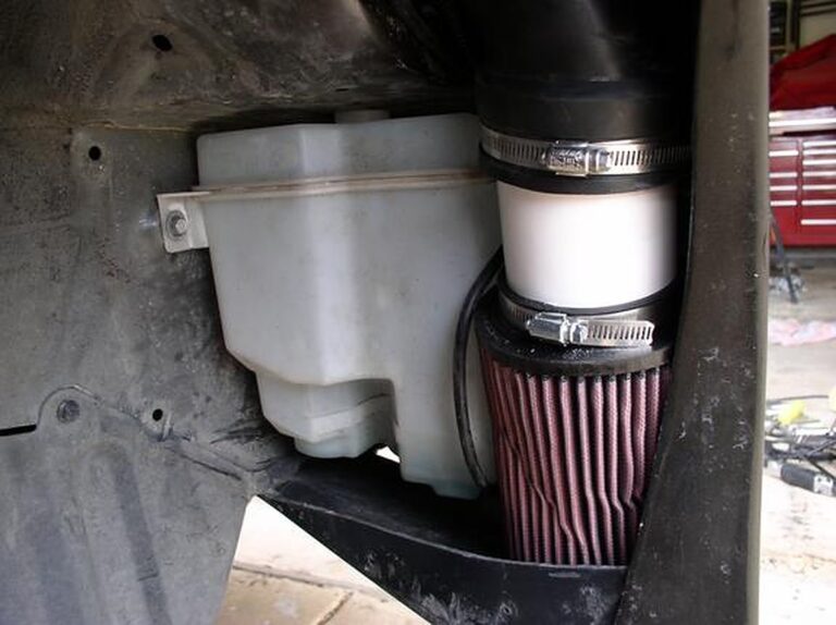
Remove the low-pressure SC pipe and cover the SC with some duck tape. (to keep shavings out of the SC) Also jack up the car and remove the passenger tire. Remove the wheel well cover and pull out the washer bottle. But first, pull out the fill neck. Just grab it and pull, it pops out (this has 2 10mm bolts that you will need to remove)
Take out the MAF and cut the 4 wires that go to the MAF. Make sure to cut all 4 wires staggered. (cut each wire 1″ than longer the next). Now cut 4 16-18 gauge wires that are 3 1/2-4 ft long. 3M Crimps connecters is what I used. Now when you get to the other end you will know that you are connecting the right wires. The stager from the MAF should match the stager of the new wire, plus your wire won’t be too thick to hide in the split loom. (do not plug in the MAF just yet)
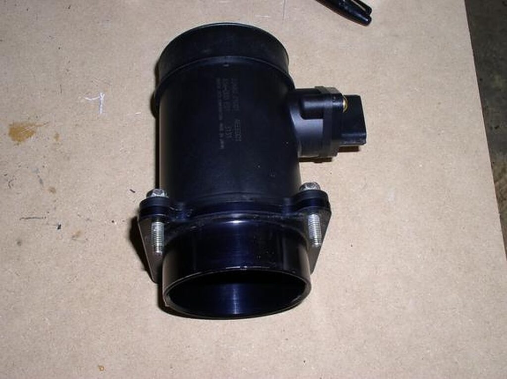
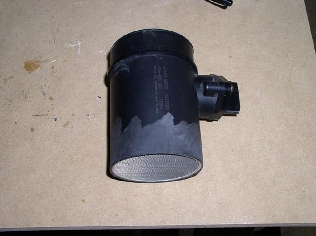
You will have to modify your MAF some. Remove the 4 bolt (10mm wrench) and then you will need to grind the flange off. Make sure that you don’t grind out the screen. Cut the 3″ silicone hoses to fit over both ends of the MAF.
Before
After
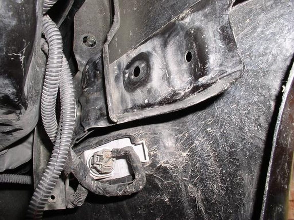
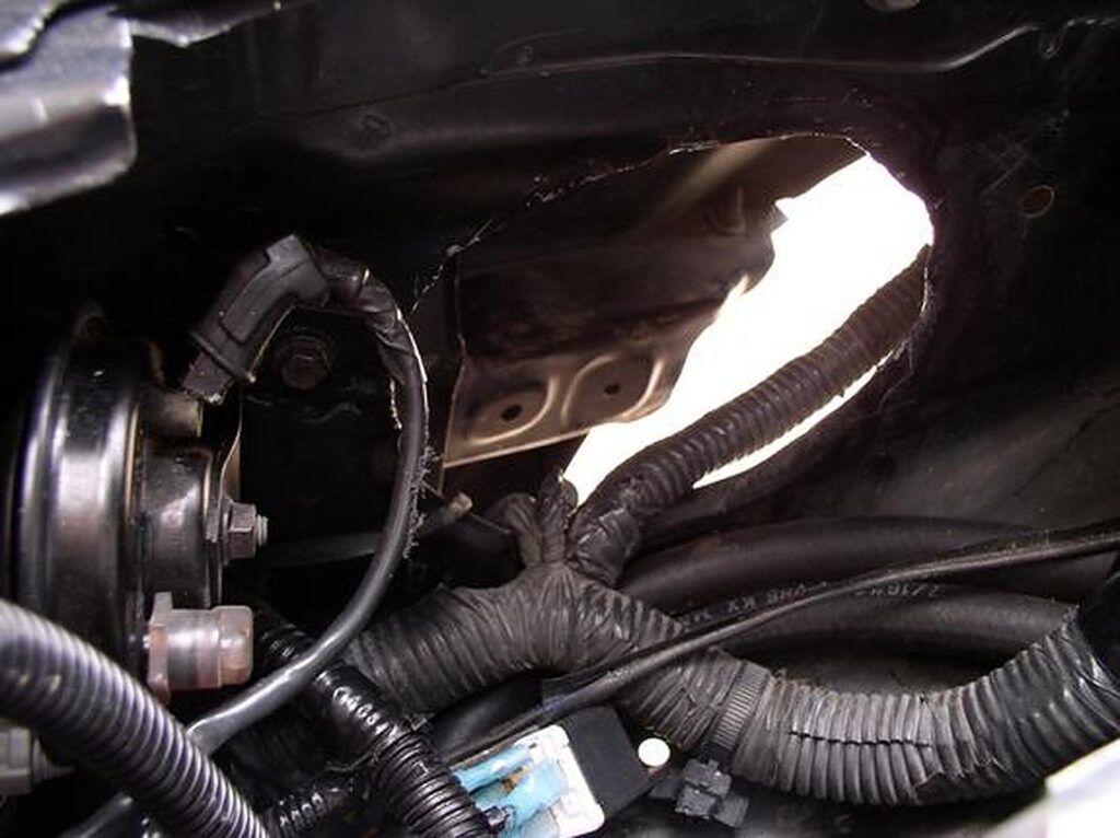
Use the MAF to get an idea of how much bigger you will have to make the hole for the piping to go thru. You will also need to cut the bracket in the fender well for clearance. (clean out all the shavings i.e.: vacuum or blow it out)
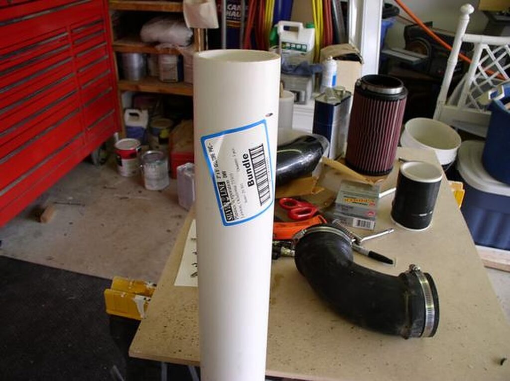
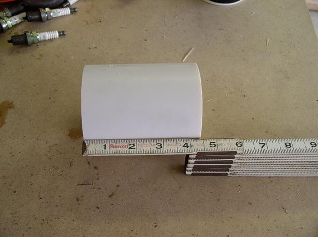
Cut the PVC pipe to about 5 1/2″ (you may want to measure for your own fit. I had a custom front bumper that is deeper. So my PVC was closer to 9″) (a miter saw works well to cut PVC).
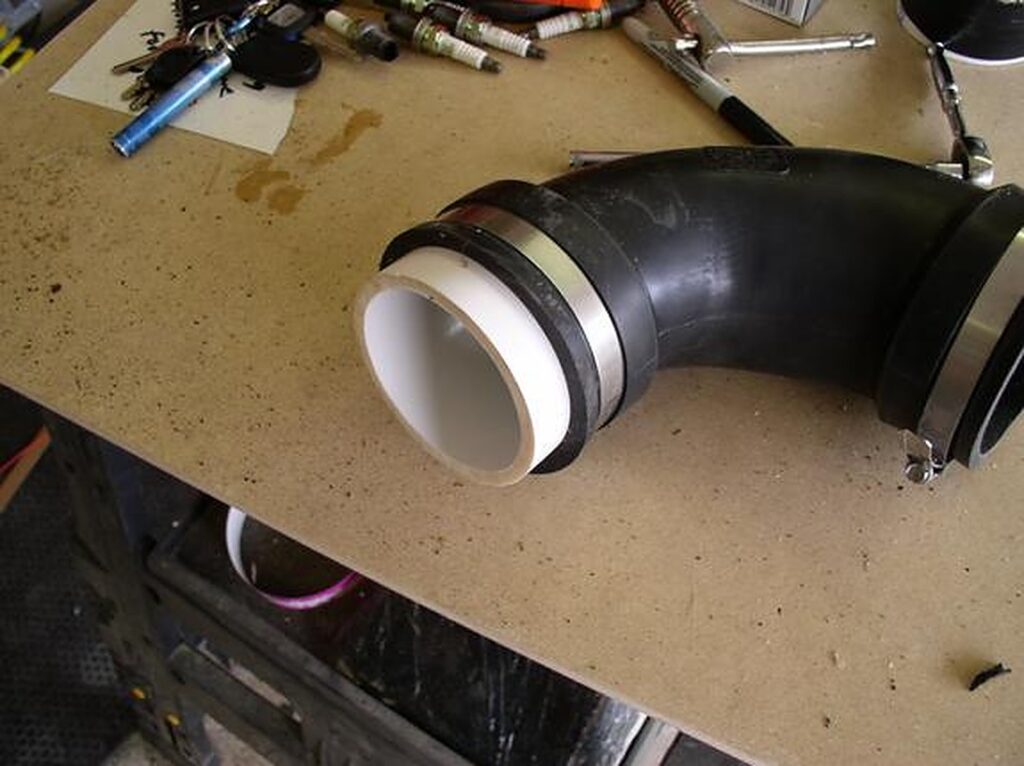
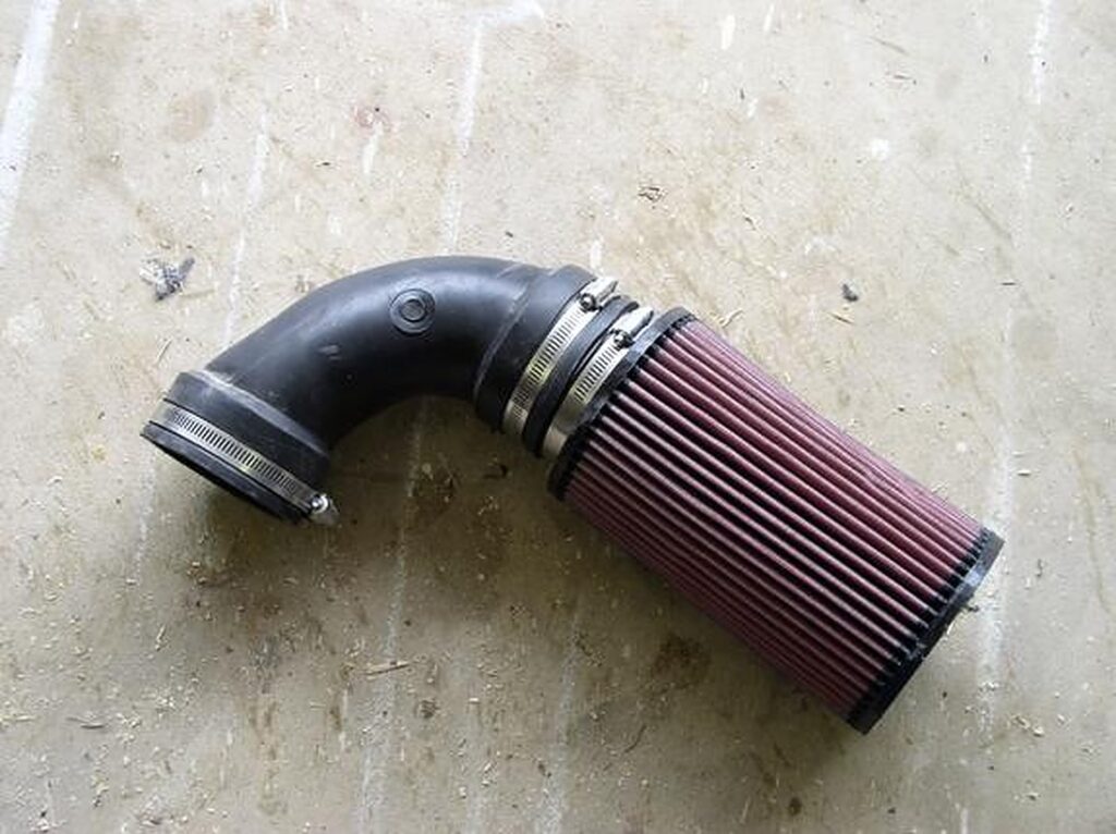
Assemble the PVC to the rubber elbow and then to the K&N filter (this way you can slide the PVC pipe up and down inside the filter to get it just right) (If you go too far into the filter take it out and cut again)
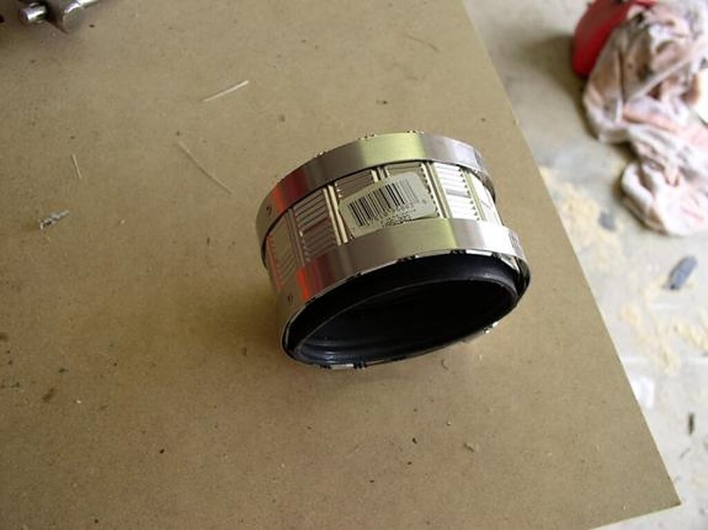
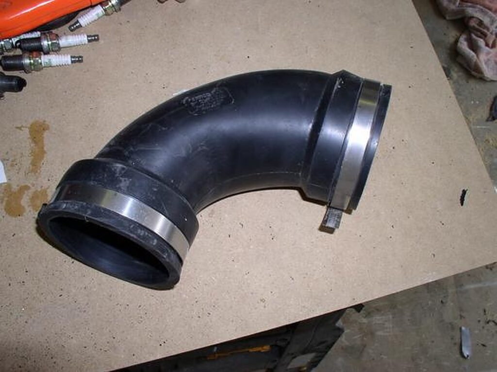
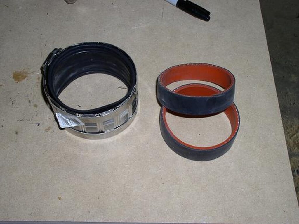
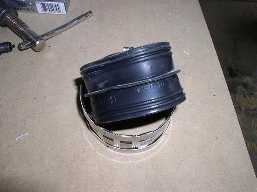
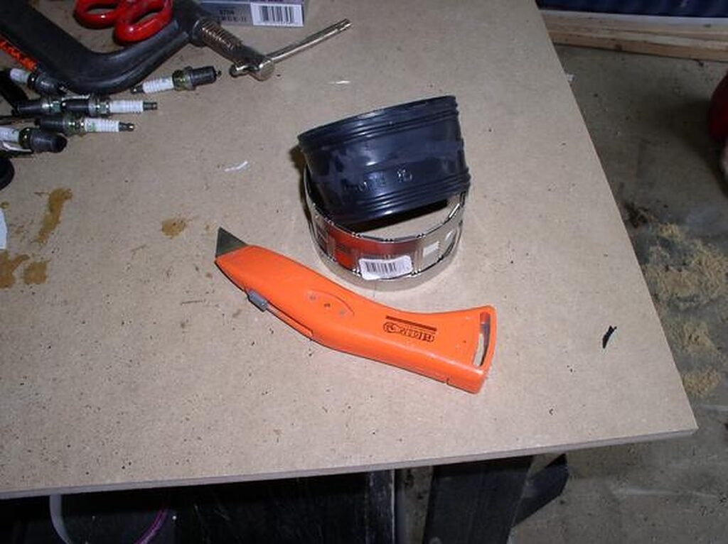
Trim the 3″ ProFlex coupling. Turn it inside out and trim it with a sharp (new) razor blade (I use a grinder or Dremel to grind off the lip in the middle).
Before
After
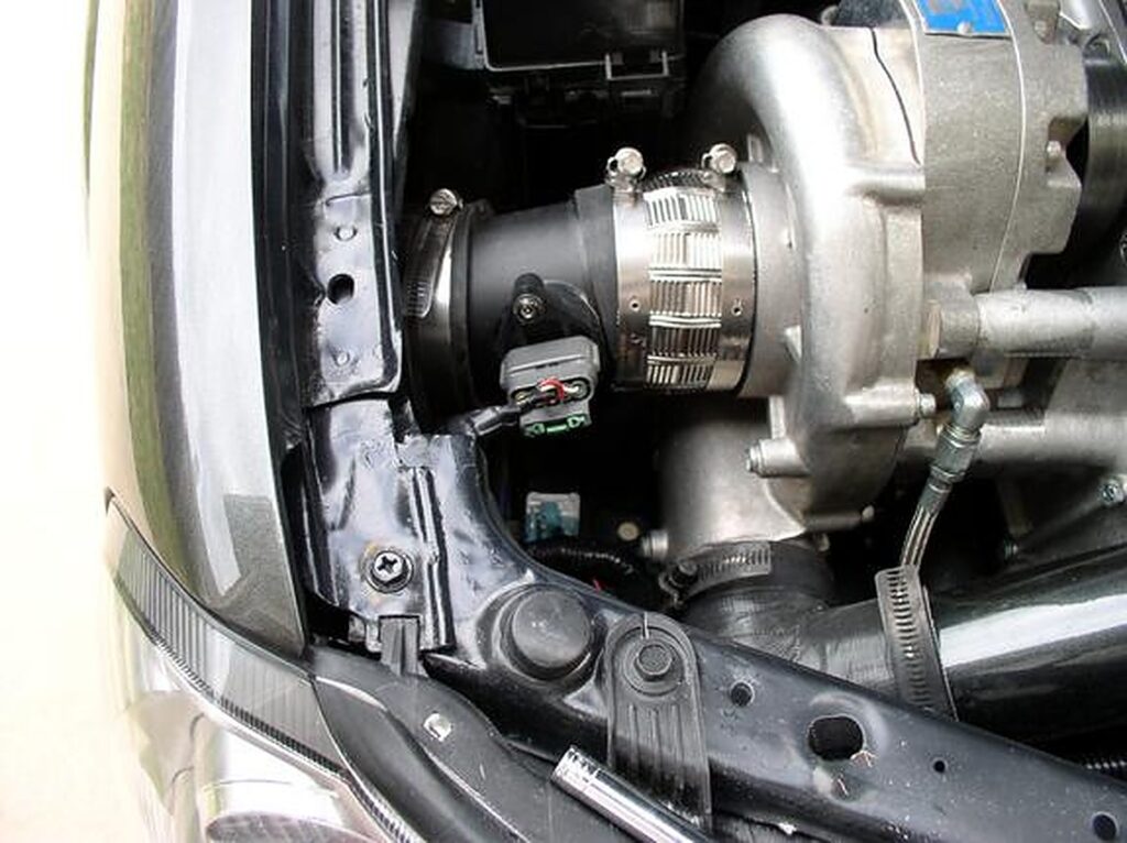
Remove the tape off of the SC and place 3″ ProFlex coupling on the SC and tighten it on there. Next, push the filter assembly thru the wheel well. Then route it so that you can place the washer bottle back in later.
Line it up with a 3″ ProFlex coupling that is attached to the SC. Mine did not go on really square (it seals just fine).
Tighten all the clamps up and place the washer bottle back in. You will only be able to get to the back bolt to the washer bottle and the filter will hold the rest in. Put your fill neck back in. Plug the MAF back in.
Start your car and feel for any leaks around your CAI.
Put the wheel well cover back on and your tire.
Test drive and see if you can feel the difference. Re-check your connections once again.


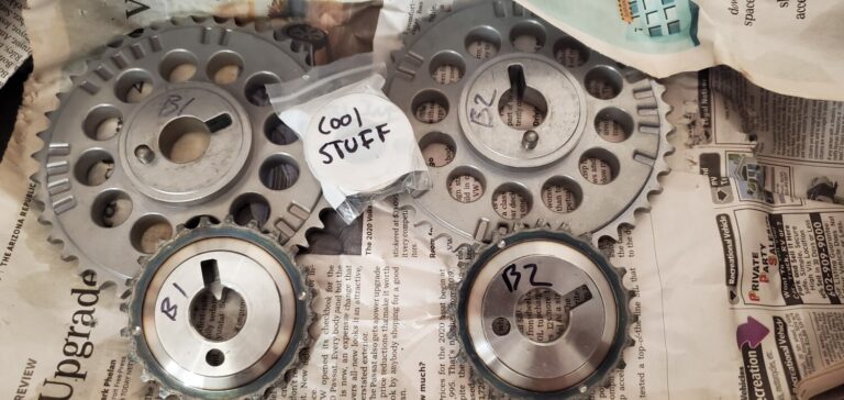
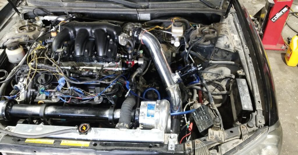
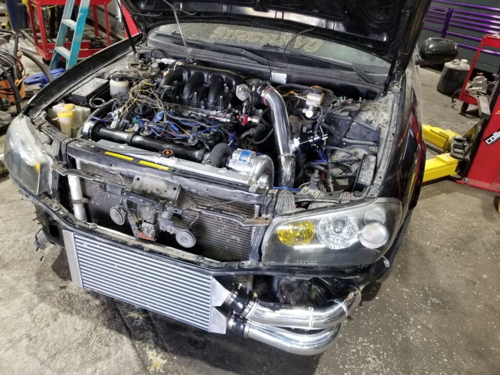
 Leonard’s Engine Bay