Category

my4thgen 95-99

Category

Community Member Credit: shadyonedeath

Materials:

I collected parts for both 00vi setup options. 4th gen LIM setup and all 5th gen LIM setup. Both of them would have used a 4th gen IACV and adapter. I am going with 5th gen lower because I decided the UIM was designed for the 5th gen lower, and I don’t mind tuning it when using the 5th gen fuel rails.

MY Swap Project:

  • 5th gen Upper intake manifold (w/ mounting hardware, throttle cable bracket and PCV hard lines)
  • 5th gen Lower intake manifold
  • 5th gen fuel rail, injectors, NO adapter. (i used the existing line/barb and didn’t need a adapter)
  • 5th gen Throttle Body
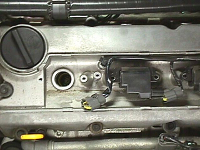
  • 5th gen Rear valve cover
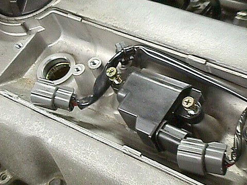
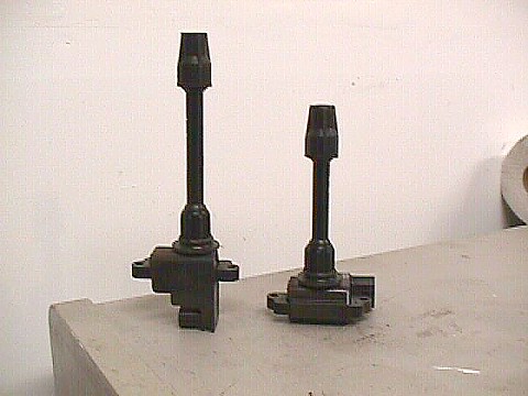
  • 5th gen Rear Coil packs
  • IACV Adapter
  • 4th gen IACV
  • Apexi VAFC2 (for tuning and Activation point)
  • Brass elbows, All threaded 1/4″. Barbs = (2) 3/8″ for Brake booster and EVAP and (1) 1/2″ for IACV)

Prepping the UIM

If you were like me, your junkyard/delivery man wasn’t too friendly with the UIM. As you can see my first UIM has the majority of nipples broken. Good thing we they’re inadequate for our 4th gen vacuum lines and we need to replace them anyway…

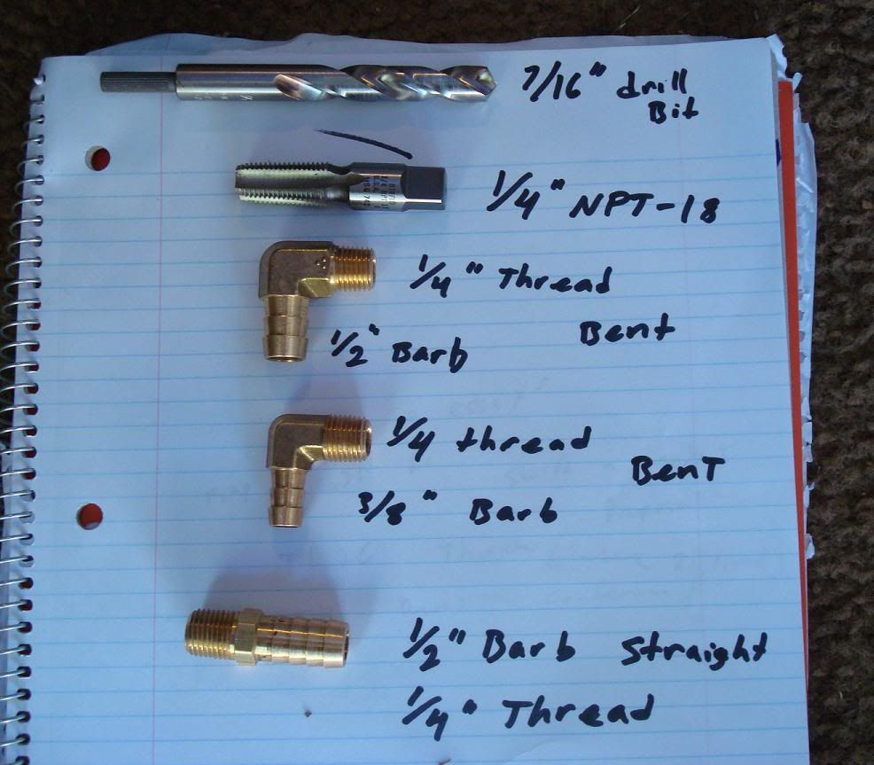
Here is what I will be using.

Materials: From top to bottom of the picture

  • 7/16″ drill bit
  • 1/4″ NPT-18 tap (available for sale, apparently my old man stocked up back in the day. They’re new and i have
  • /4″, 3/8″, and 1/2″)
  • Brass elbows All threaded 1/4″
  • Barbs vary from:
    (2) 3/8″ 90 degree elbows for Brake booster and EVAP
    (1) 1/2″ 90 degree elbows for IACV

Note: Ignore the Straight brass fitting in the picture. Didnt use it. 90 degree bent elbows work best. I used two 3/8″ x 1/4″ elbows and one 1/2″ x 1/4 elbow.

The straight 1/2″ barb is for the IACV adapter.
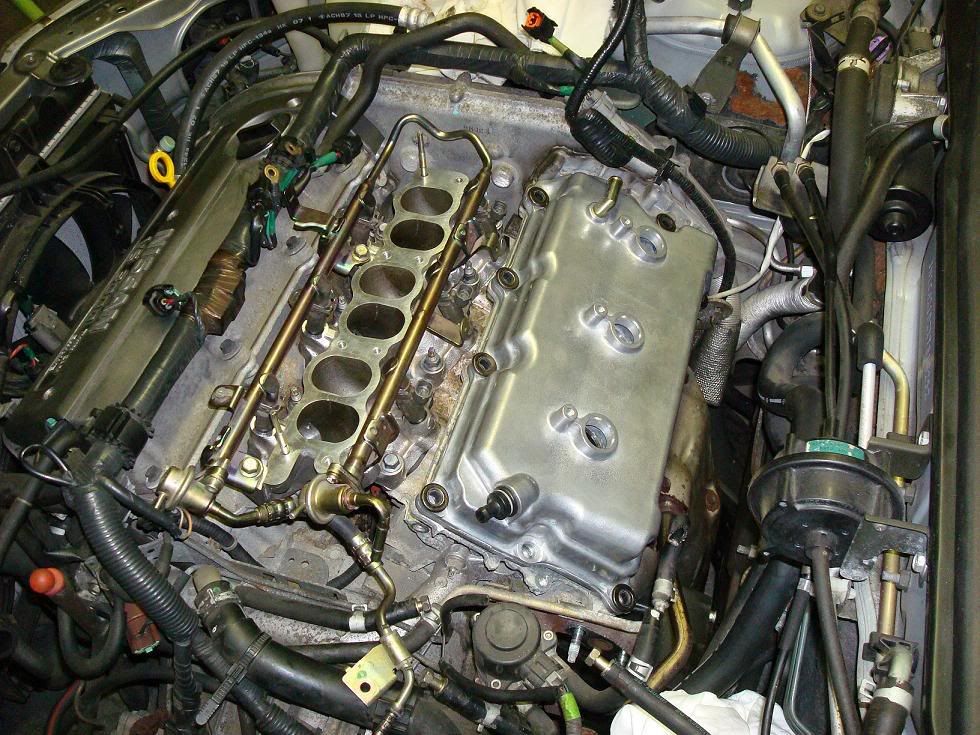
Lets start with the EVAP line located on TOP of the UIM where the Throttle body bolts up. Number (4) on the Diagram.

Damaged tower but still has plenty of meat to work with. First step, drill it out using a smaller 3/8″ drill bit, and move up to a 7/16″ bit to reduce stress. The 1/4 NPT-18 tap requires a 7/16″ hole.

Note: Either this plastic material is super fragile or my tap was razor sharp, but it cut through like butter. Make sure you know how deep your tap has gone so you don’t accidentally ruin your threads by over-turning it.

Result. Make sure you use some tweezers to pluck off excess plastic and prevent it from getting sucked in to your car later. Once its all clean, insert your 3/8″ barb x 1/4″ threaded brass fitting here, and your done. I also used RED permanent loctite (thread lock) to seal it up real good. You will probably want to use some RTV instead of loctite. I didnt, but i will if i encounter any leaks during the install.

Next, the brake booster line. Number (1) in the diagram.. Cut the existing nipple flush with the wall of the manifold and drill using 7/16″ bit. Careful, don’t go too deep, not a lot of meat in there, and you’ll quickly hit a wall inside the manifold. Just drill enough to widen the hole for tapping.

I then pulled out the rubber cap covering a small nipple underneath the brake booster nipple and cut it away enough to allow my brass fitting to screw in. Don’t cut it all the way to the wall like the brake booster nipple above it, leave some nipple there and cover it back up with the rubber cap along with some sealant. This will avoid the hassle of sealing it up with something like JB weld and getting sucked in.

Last, the IACV line, port 5 in the diagram. The brass elbow used is a 90 degree 1/2″ barb x 1/4″ threaded brass fitting that’s required to give enough air flow to the IACV adapter to prevent idle issues. I used a hacksaw to cut the tower behind the existing nipple. I then used my smaller 3/8″ drill bit to enlarge the hole, followed by 7/16″ drill bit. I then used my tap, and ended with the brass fitting and some loctite.

Edit: Don’t use Loctite. When it dries, it gets hard. Hard = cracking if you later want to re-position the nipple in a different angle. You dont want pieces of loctite in your engine. If i were to do it again i’d use High Temp RTV. Its orange and flexible when hard.

Note: These brass fittings are a ***** to get in. Once you’ve twisted beyond the strength of your hand, use a wrench to torque it in there.

Both fittings shown. The reason the top tower for the EVAP is still in tact is because i need to get another 90 degree 3/8 barbed elbow but the hardware store is closed. I WAS going to use the straight one but the hole that supplies that tower with vacuum is too small. I need to cut it off completely and enlarge the hole all the way through the manifold. Also, the process shown in the first drilling of the EVAP line was from my 2nd manifold which i will be selling. I prepped both manifolds for threads but only installed nipples in one.

Update: Top tower fitting installed

Painting 00vi Upper Manifold

Materials:

  • 400-800 grit sand paper
  • Rubbing alcohol
  • Masking/scotch/painters tape
  • High Temp engine paint (gloss black)

Process:

Pretty simple: sand smooth, clean with rubbing alcohol, mask important areas with tape and paint.

Here I used some left over graphite colored wheel spray paint and “flaked” it from a distance to give it a diff. look.

00vi Swap : The Removal I recommend getting your models Factory service Manual for reference.

If you’re attempting the 00vi swap you should be fairly familiar with what needs to be removed and how to remove them. I’ll try and go through the basics. Also, before you start, i recommend your protect your fenders with some type of cover between your knees/clothes and the paint. I used some brown wrapping paper and Painters tape to cover both fenders and areas pained near the engine bay. I also recommend you label your hoses and there they go. Use whatever it takes because no matter how good you think your memory is, you WILL lose track of dangling hoses.

A – Battery
B – Air Box
C – Mass Air Flow Sensor MAF (Handle with care…we don’t need more problems when troubleshooting your 00vi install)
D – Throttle Body – 4th Gen TB’s have a) Throttle Cables, b) Coolant lines (I plugged mine with bolts removed in the process to prevent spilling), c) Connectors (Throttle Position sensors, Brown and Black/Gray) that need to be removed.
E – Electrical log/Harness – This connects to: a) Coil Packs, b) EVAP valve c) EGR temp sensor, d) EGR unit itself, e) Throttle Position sensor. Remove these and the log can be bent out of the way towards passenger side of engine bay.

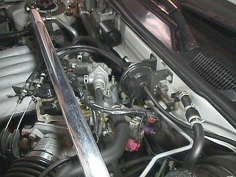
F – Upper Intake Manifold – Mine had 4 bolts up front towards bumper and 4(?) in the rear attached to mounting brackets. Stick your hand back there and familiarize yourself with the brackets and the number of bolts. Not 100% sure how many there are back there. UIM also has the throttle cables mounted to the bracket, loosen the cables and they slip off the bracket. If your 00vi didnt come with a bracket, avoid removing the cables and just remove the bracket itself and push/tape out of the way. The EVAP valve is also on top of the UIM, remove it and get it out of the way. Your PVC line will also be attached to the UIM, remove the vacuum hose. Behind the UIM, your EGR tube is attached, there are 2 bolts holding it. Under the EGR tube are 2 short coolant lines that run through the UIM. I didnt bother removing mine properly due to the tight space, i just took a knife to the hoses since I replaced the two EGR coolant lines and make a “UIM/Throttle Body coolant bypass”. Remember to note which one Runs coolant and which one Returns it, they lead back to the coolant log near the front Valve cover/ Knock sensor connector cable.

G – EVAP valve
H- Not visible in picture but this is where you Idle Air Control Valve is. (IACV)

(ignore the “stand alone” label)

Here is your EGR tube removal since you need to use the 5th gen EGR tube with the 5th gen Upper Intake Manifold. I used a Dremel and a cutting wheel to cut the stud tip off. This is necessary to remove the nut holding the EGR tube itself, since that brass looking tube is in the way. I’ve read you can also cut it using a hacksaw blade…without the handle. Might take a while though. Make sure you plug/cover your fuel lines before grinding away here to avoid any unwanted ignitions.

Rear valve cover and Lower Intake manifold

Pretty straight forward, unbolt and replace. Use new crush gaskets for the LIM and if your Valve cover gasket is still good, use some Ultra Black RTV. I failed to do so and had a oil leak, had to remove everything, clean the oil off the gasket/valve cover, and RTV the gasket into the valve cover grove, then RTV on the gasket to the head. For the LIM, i took my time torquing the bolts, little by little, starting from the middle, outward. Search for the torquing procedure on the org or in your Factory service manual. Same with Rear valve cover. Also, inspect your new rear valve cover’s rubber grommets. There’s four, 1- PCV, and 3 for spark plug tubes.
Fuel Lines:

Ignore the tags. (VAFC2 Vafc 2 VAFCII VAFC II )

I bought my Apexi VAFC2 used and it was missing the 20 gauge extension harness. The wires on the main unit itself are VERY fine, above 22 gauge, and would not be easy to work with when splicing into the ECU.

What I did was take a old Computer Power supply and use the 20 gauge wires as an extension/adapter for my splice connectors.

Materials:

-Splice connectors. Can be found at radio shack.

-Soldering iron / solder
-electrical tape
-Wire stripper
-Wire cutters
-Sacrificial Computer Power Supply Unit wires
-VAFC2 harness (the VAFC2 is inside the glove to protect it… )
-wet sponge (cleaning iron tip)

Note: If i could do it again, instead of cutting wires off the Power supply unit, i would have cut off an entire Power supply unit harness with connectors attached and used that as a removable connection to my VAFC2. The PSU clips would have been useful.

First, i started stripping ends of the PSU wire. If your lucky, you’ll find matching colors to your VAFC2 harness. I found all of them except for brown and pink. For brown i used Black, as it is a ground, and Orange for Pink.

To strip the super thin wires from the VAFC2 harness itself, i used a new razor blade and gently twisted it around the wire. I then bent the wire to expose the cut and pulled off the insulation with my finger nails. Use common sense on applying pressure on the blade.

My method of soldering is pretty amateurish but i don’t care. As long as you make a solid connection, any method works. I just twisted both ends of the wires and bent the tip back with pliers.

Followed by solder.

I then used electrical tape to seal the connections. Others will suggest heat shrink wrap but i couldn’t find any @ Home Depot, radio shack, or auto zone. The result.

Note: Maxima’s DO NOT use VAFC2 wires: ORANGE, LIGHT BLUE, and PURPLE. I covered each tip with electrical tape and then taped them all together and stuffed them back in the main insulation on the VAFC. See diagram in next post for wiring.

Before you do ANY of this, make sure you disconnect your Negative battery terminal before you work on splicing into the ECU.

Here we have the wiring. There are two power wires (red) and two ground wires (one black and one brown) required to function the VAFC2. Each set is spliced into the same Power or Ground in on the ECU harness and spaced apart 1cm or more. The MAF wire on the ECU harness must be CUT, not spliced. Once cut, the end still attached to the ECU CONNECTOR/CLIP is connected to the YELLOW wire on the VAFC2 harness. The other end of the MAF wire we cut is attached to the WHITE wire of the VAFC2 harness.

Refer to YOUR Maxima model’s Factory Service Manual for correct wire colors on the ECU harness. Wire listings can be found in section EC under ECM Terminals and Reference Value.

Note: I haven’t messed with the MAF wire yet because i need to get some plugs for the wiring. These plugs will allow the MAF wire to be reconnected to its original form easily should you choose to remove the VAFC2. Also it helps make a cleaner and secure install. I also avoided splicing into the Knock Sensor wire, apparently this caused some issues with the car starting and previous installers have avoided this part of the install. Please correct me if im wrong on this.

Edit: DO NOT use knock sensor wire. We dont need it. – per gtr_rider. Its not designed for our cars

Go to the Passenger side and remove the cover concealing the rear of the ECU/ECM. You will see a white plastic cover over the wire harness. Use a 10mm socket wrench to remove the bolt and then proceed to remove the harness/clip from the ECU. Once off, give the harness a bit of a tug to expose more working space. Nothing to drastic, just enough to get an extra inch or two. Remove the white/clear plastic cover from the harness clip using a flat head screw driver. Now we can begin searching for our desired wires.

Splice connectors are pretty self explanatory.

Don’t ask me how im going to get the plastic cover from the ECU harness back on, i probably wont.

Plug ECU harness back in, bolt it on, and reconnect your negative battery terminal. Turn key to ON position and if all connections are correct, enjoy your working VAFC2. I did it on my first try.

Note: The Yellowand white wire above are for the MAF wire. I didn’t get to this yet as i need some plug connectors. The Blue wire i believe is for a Wideband 02 sensor for tuning. Don’t have this yet, so also not used. The Orange wire you see is actually routed to the PINK wire on the VAFC2. PINK wire is used to send the 12v signal to the VIAS to activate the 00vi.

All systems go. At first my RPM signal wasnt working. I went back and made sure the tachmeter connecter was fully spliced using a pair of pliers. It did the trick and everything functions correctly.

I finally got some more brass fittings from ebay. My local source ran out of them and they were getting a bit pricey. (5$ a elbow). I got (6) 3/8 x 1/4 elbow fittings for about 10$.

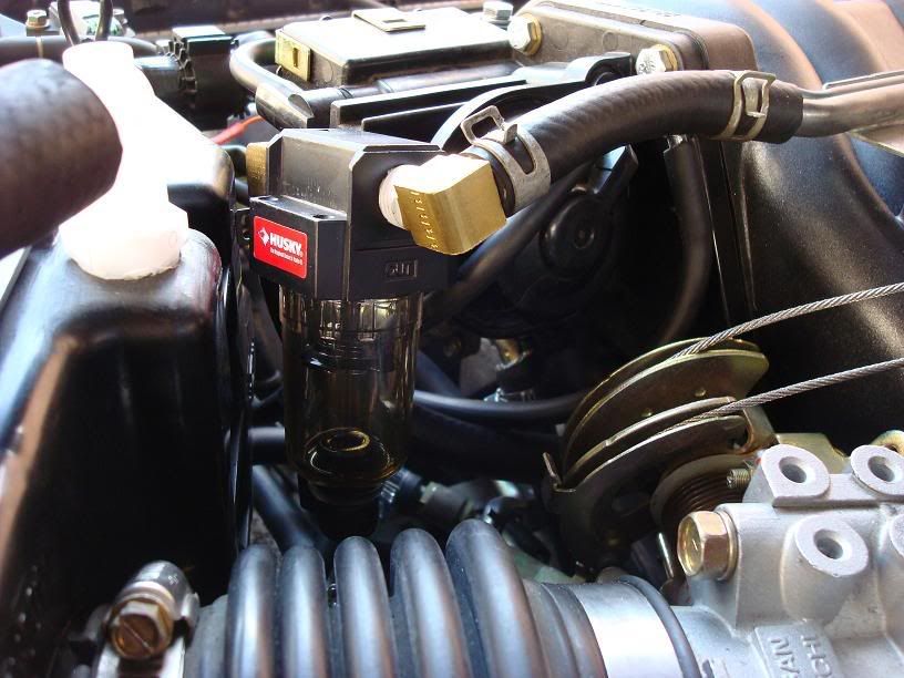
Why six? Well, i need two for the 2nd 00vi im going to sell, 2 for my oil catch can, and 1 for my current 00vi, which i painted in above posts.

-5th gen Upper intake manifold
-5th gen Lower intake manifold
-5th gen fuel rail w/Damper and FPR, No adapter.
-5th gen FBJC100 290cc injectors
-5th gen Throttle Body
-5th gen Rear valve cover
-5th gen Rear Coil packs
-5th gen Snorkel & Air box modified to fit 4th gen MAF
-IACV Adapter
-4th gen Idle Air Control Valve
-Apexi VAFC2
-Husky (Home Depot) Oil Catch Can

 

Loading

Community Member Credit: Jeff Ketch

Here is a list of things that need to be done for the 60K service.
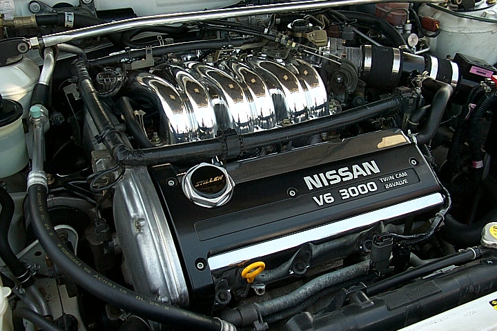
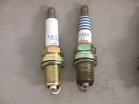
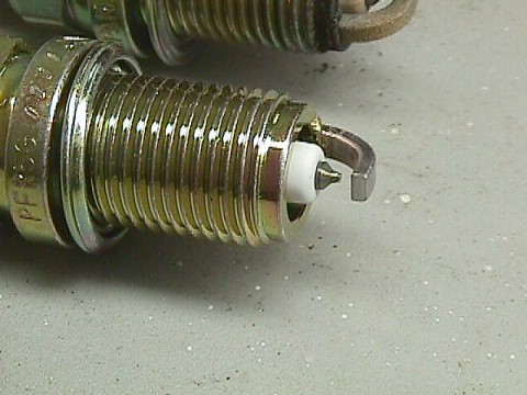
  1. Spark Plugs: 6 NGK Platinum spark plugs are required for the tune-up. Platinum plugs do not need to be gapped. If you use copper plugs the gap is .044. Put anti-seize on the spark plug threads and torque to 18 ft/lbs. The spark plug socket is 16mm or 5/8. The spark chambers are very deep as you will find out. A magnet will help to remove and install the plugs. Also a couple of socket extensions are necessary. Remove the spark plug cover (Nissan V6 3000) to reveal the front three plugs. The rear three plugs are behind the exhaust manifolds. The last picture shows an approximate location.
           
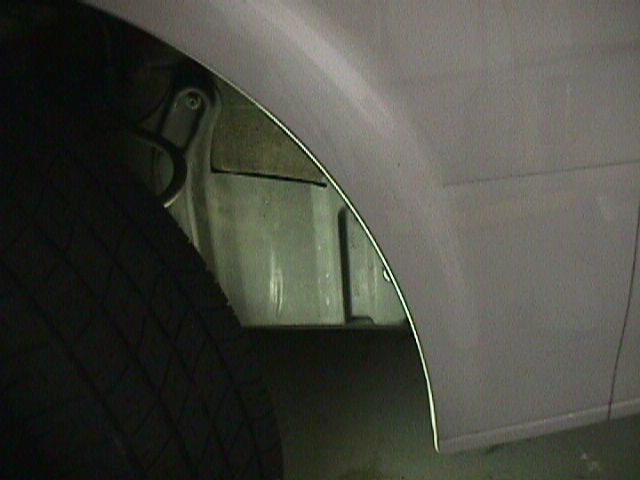
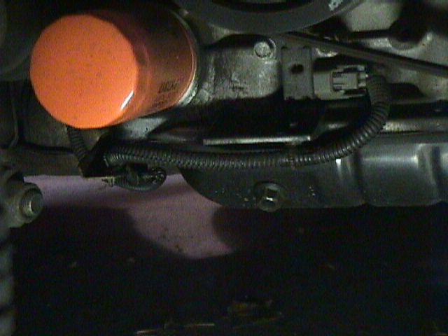
  2. Oil Change: Make sure the car is on a flat surface. Turn the steering wheel all the way to the right. The filter and plug are behind a panel in the passenger fender well. There are about 4 Phillips head screws holding the panel in place. There is one more Phillips head screw under the front nose of the car that needs to be removed. Once the panel is removed you can see the plug and filter. Remove the drain plug (turn left) and make sure that you keep the crush ring that is on the drain plug. Nissan recommends that you replace the crush ring ever oil change. The ring should be good for about 3-4 oil changes. Remove the old oil filter and then reinstall the oil plug. Put fresh oil into the new filter and install. When the filter gives slight resistance turn it another 2/3 of a turn. Tightening the filter by hand is all that is needed. Add 4 quarts of fresh oil and then start the car. The car takes 4.5 quarts but make sure that you do not over fill. The Nissan filter # 15208-31U00.
  3.  
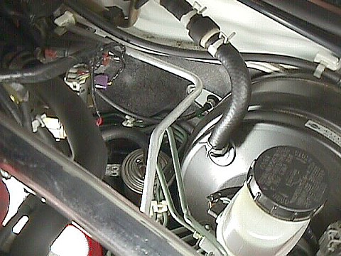
  4. Fuel Filter: The filter is located against the fire wall near the brake fluid. There is no real easy way to remove the filter. It has a hose clamp at the top and bottom of the filter. The hose clamps are tightened with Phillips head screws. The problem is Nissan did not leave a lot of room to get a screwdriver in there in order to remove the filter. If you want to attempt to change the filter here are a few tips. Leave the car running. You will need to remove the fuel pump fuse. The fuse panel is under the steering wheel on the left. Locate the fuel pump fuse and remove it. In about 5-10 seconds the car will stall. Try to start the car at least one more time. This releases the pressure in the fuel line. Turn the car off completely. Now try and remove the top and bottom hose on the filter. When reinstalling the filter make sure that you don’t install upside down. When new filter is installed put the fuse back in and start the car.
     
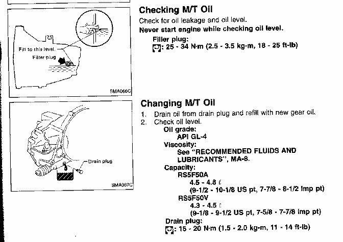
  5. Transmission Fluid: The drain is under the transmission near the driver’s side of the car. The fill is in the front of the engine and looks like a large square opening. In order to open that fill plug you need a 1/2″ ratchet with out the socket. The transmission takes 4.5 quarts of MT-90. I have provided a picture from the shop manual to show the location of the drain bolt and fill plug. Easy way to fill the transmission is to get some plastic tubing and tape a funnel to one end.
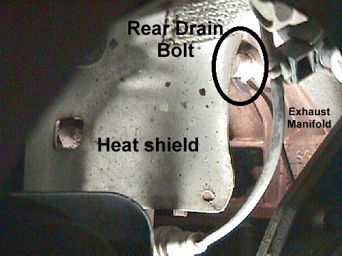
  6. Radiator Coolant: The radiator takes 9.5 quarts of fluid. The mixture is 50% coolant and 50% distilled water. There are 3 drains that you need to find. One is the radiator drain which is directly under the radiator. The second is in front of the engine dead center near the exhaust manifold. Third is in back of the engine. Here is a picture of the third drain bolt. If you take off the passenger front tire, look on the left side of the front shocks and turn your head a little to the right. That is were the picture is looking. The bolt is in the top right of the picture left of the black wire. I had the dealer to it for under $50.
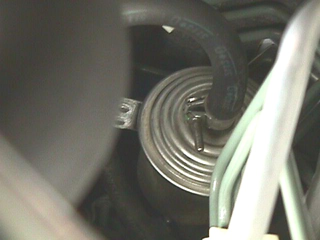
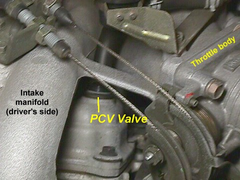
  7. PCV Valve: The location of the valve is not longer a mystery. Located near the throttle body.
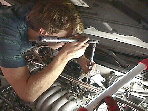
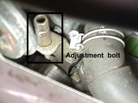
  8. Belt Replacement: The ’95 has two accessory belts. One is the alternator and the other is compressor/power steering. This jobs took me over a hour to complete. You will need long combination wrenches and sockets. The sizes are 12 and 14 millimeter. Please note how tight the belts are because you have to adjust the belt accordingly. It’s call “deflection” so please push on the belts and remember. After the install you need to get the belts close to the same deflection.

    Take off the passenger side front wheel and the oil cover. This will expose the belts.


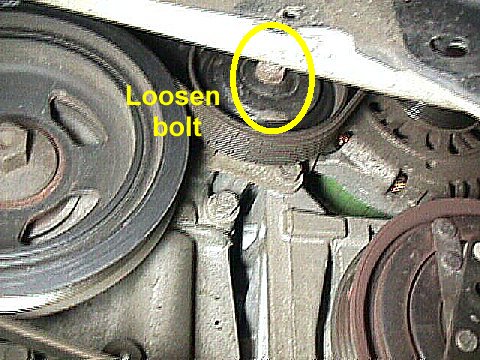
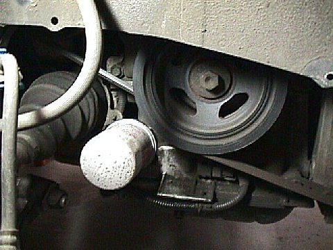
    View from under the car. Looking at the center pulley. You have to loosen the bolt in the middle of the pulley. Then directly above is the adjustment bolt that you will loosen to raise the pulley. The next picture shows the top bolt.


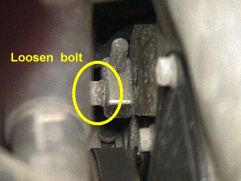
    View from the top passenger fender looking near time chain cover. Loosen the bolt so that you can raise the center pulley. This is the belt that needs to be removed first.


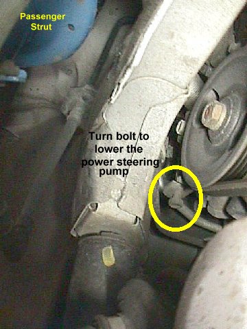
    View from the top looking to the left. Loosen the bolt so that you can lower the power steering pump. There is a bolt on the other end of the threads that you can’t see. That bolt will lower the pump.


    View from the bottom of the car. Tighten the bolt so that you can lower the power steering pump. The bolt is threaded into a clamp that when tightened the clamp closes, lowering the power steering pump.
  9. Tighten throttle cable: Make sure the cable is low and in-between the half moon shape. The cable at the relaxed state should not be above the half moon…there needs to be more tension. The outside cable is your cruise control and the inside is your throttle. To fix this follow the cable about 6 inches back to two nuts. Loose the front nut and spin that forward, the cable will come loose but now you spin the back nut in the same direction and that will take up the slack along with securing the cable to the mounting bracket.
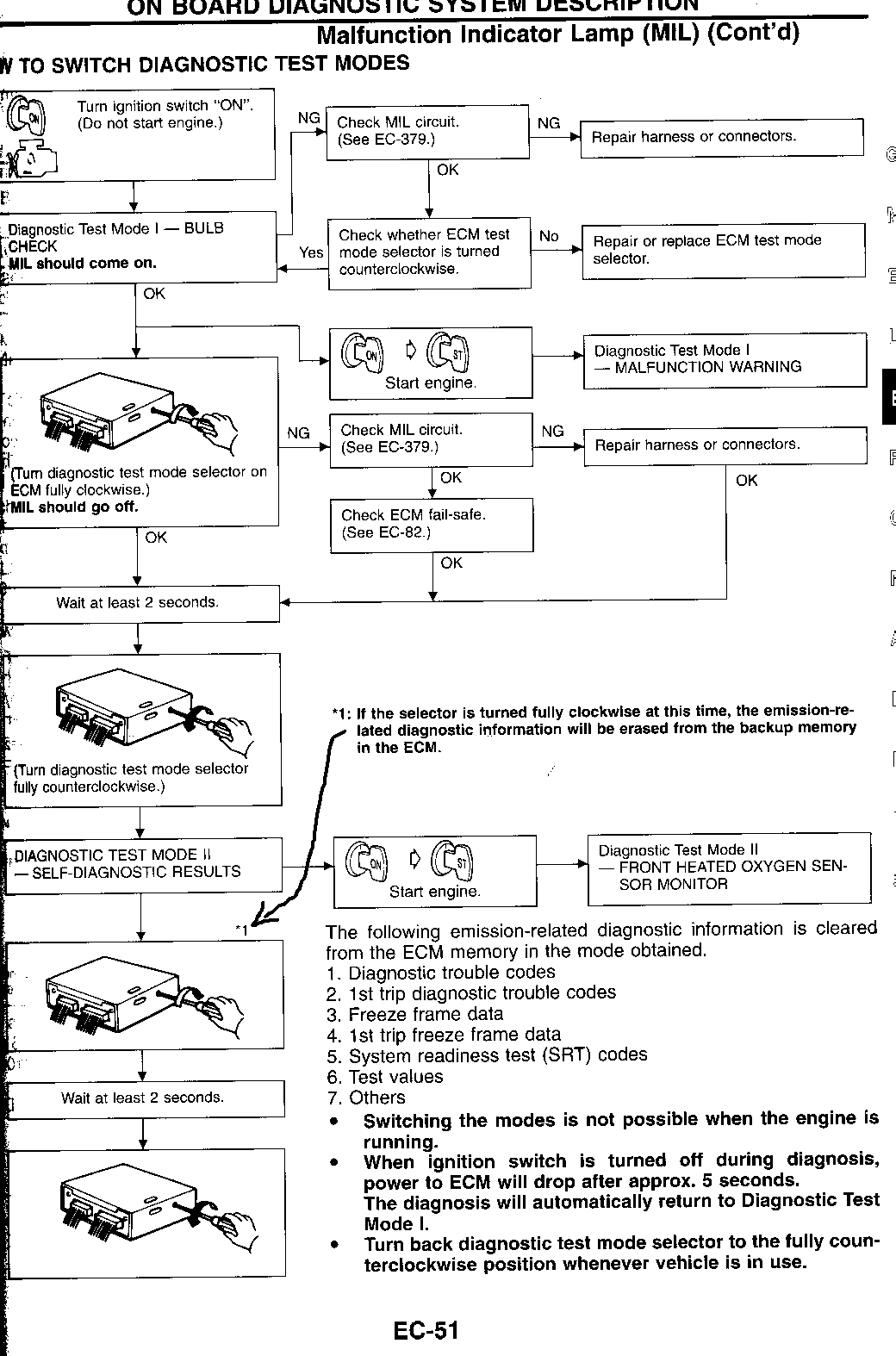
  10. ECU reset: This is not needed for the 60K service. If the “check engine light” comes on. This is the proper way to reset it. Andi is the one who scanned the page.

Loading

Community Member Credit: luke95gxe

So I decided to install a cold air intake the diff is noticeable and I love it.

Tools Needed

  • Flathead Screwdriver or 8MM Socket
  • Phillips Head Screwdriver
  • Drill Bit
  • Sawzall

Parts Needed

  • Cold Air Intake Piping
  • 3” Rubber Coupling with Clamps

My ram air intake set up:

Here is the pipe I used. It was beaten up so I painted it.

Remove fuse box and battery on driverside drill pilot holes and cut a hole a lil bigger than 3” in diameter.

Remove drivers-side wheel

Remove the splash guard by Phillips head screws you don’t have to completely remove.

Install cold air piping through the hole

Install air filter

Put splash guard back on and wheel and enjoy a better breathing engine. Finished product

I can definitely feel a difference on pulls than the ram air intake feel free to comment sorry for the crappy pics taken with my cell phone.

Loading

Community Member Credit: EnervinE

Figured I’d do a write-up because there’s next to no information about this procedure on this site. That, and a shop wanted $350 to remove and install – talk about a joke.

This is generally regarded as an extremely frustrating, time-consuming, impossible procedure, but in reality it’s quite easy if you know what you’re doing and you use a couple tricks I discovered. The driver’s side, since I had no idea what I was doing, took me roughly four hours of work, along with many bruises and foul words uttered. However, the passenger’s side, even with taking all of these pictures, only took me about an hour.

Following these instructions, I’d say this job’s about a 3 out of 10 on a difficulty scale. Don’t let a shop gouge you for this job, you can do it without much trouble.

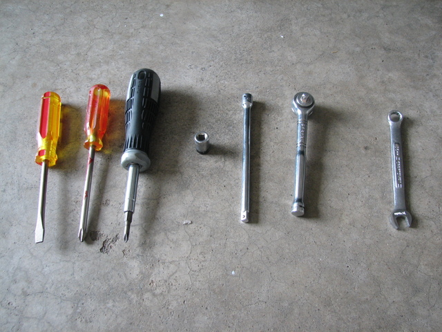
TOOLS NEEDED:

Flathead screwdriver
Small and large Phillips head screwdrivers
10 mm socket and extension
Ratchet
10 mm wrench
Optional: Magnetic grabber (bolts like to fall out of your hands and into the door crevices…this helps.)

Okay, let’s get started!

FRONT DOOR1. Make sure the window is rolled up before beginning work.

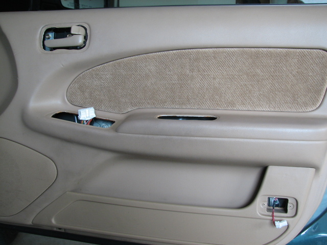
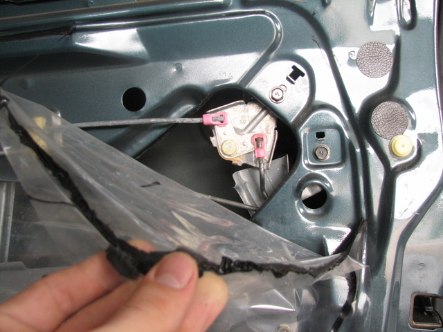
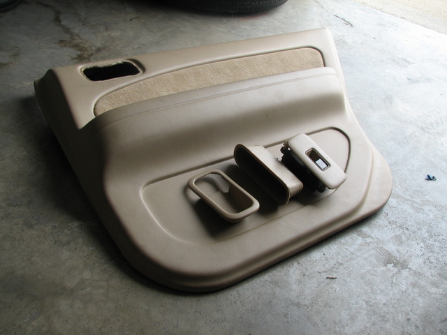
2. Remove all accessories on the inner door panel. Pop the handle trim off with a flathead. Be gentle, as it will snap with too much force. Remove the cup handle’s screw and pop it out. Use a flathead to remove the window switch. Undo the connector and set it aside. Remove the light’s lens, remove the two screws, and undo the connector.

3. Remove the two screws on the bottom of the door panel.
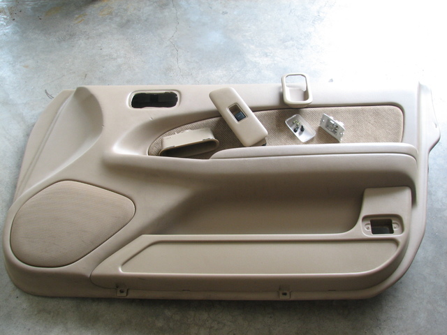
4. Remove the door panel. It is held in by a bunch of snap-in pieces that Nissan likes to use everywhere. Lift it upwards and away and set it aside with all of its accessories. (note: the driver’s side has an extra connector on the back for the trunk popper. Remove it.)

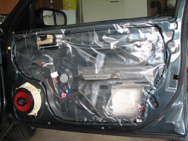
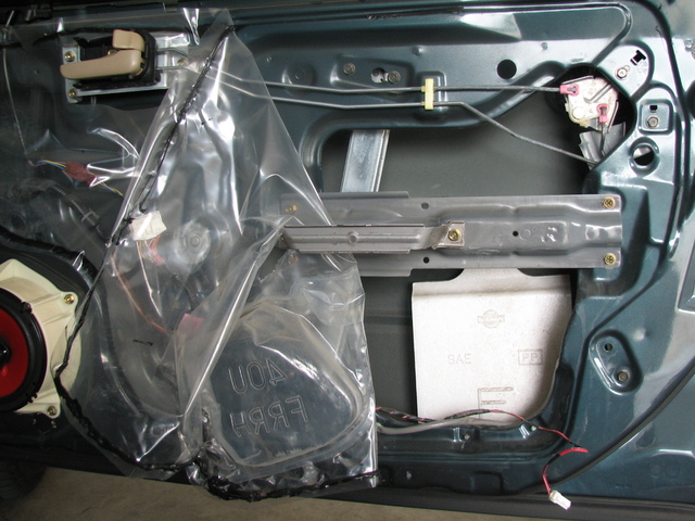
5. You should now be looking at the door with the panel removed.

6. Start peeling away the weather covering. It is sealed with a black goop. Try to conserve the integrity of the goop so you don’t have to apply more sealant when you replace the covering.

7. Peel away enough to give you some room to work with.

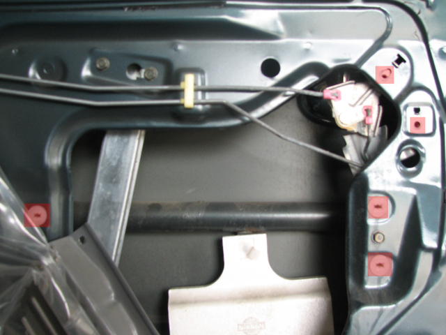
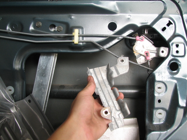
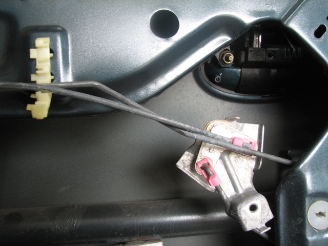
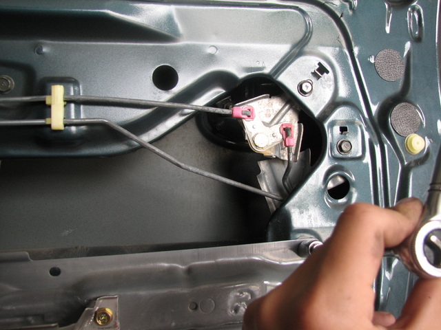
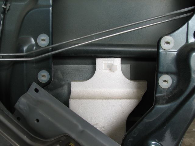
8. Remove the bolts highlighted in the picture below – 5 in total. Push the middle bar downwards and out of the way.

9. Remove the lower bolt holding this metal piece in and remove it.

10. Unclip the whiteish-yellow piece holding the two bars in place. Move the assembly downward and out of the way.

11. Remove the left nut holding the handle in place.

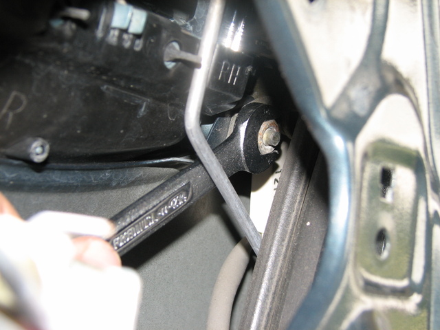
12. Use the 10 mm wrench to remove the right nut holding the handle in place.

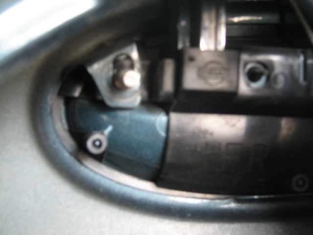
13. Pull out the bar inserted into the handle, shown removed below:

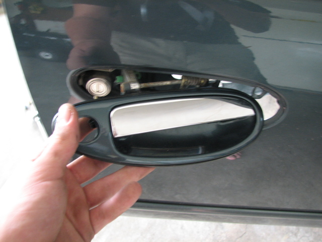
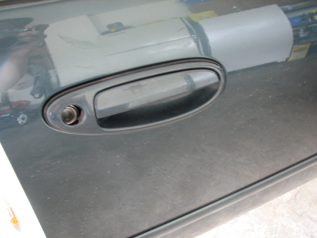
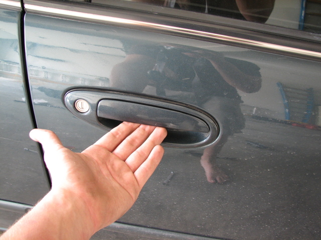
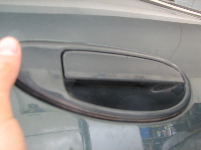
14. Remove the handle from the outside.

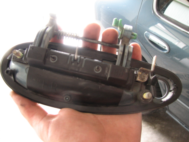
15. Examine the replacement handle. Make sure it operates correctly and has everything installed on the reverse side.

16. Insert the handle most of the way into the door.

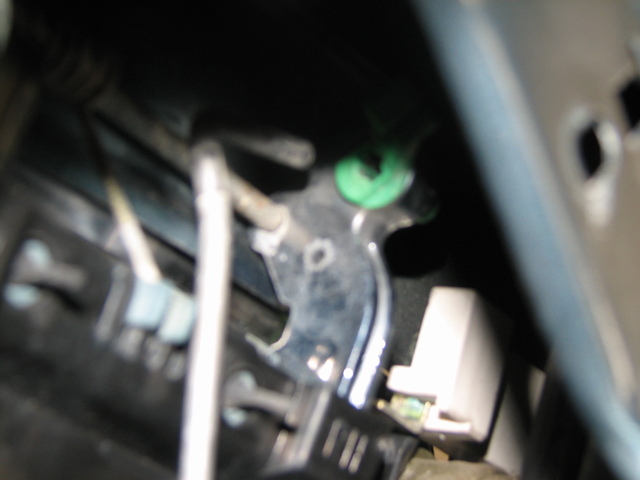
17. On the back side, line up the bracket for the keyhole with the bolt on the back of the handle. It won’t go all of the way through yet, as the keyhole is not inserted into the handle.

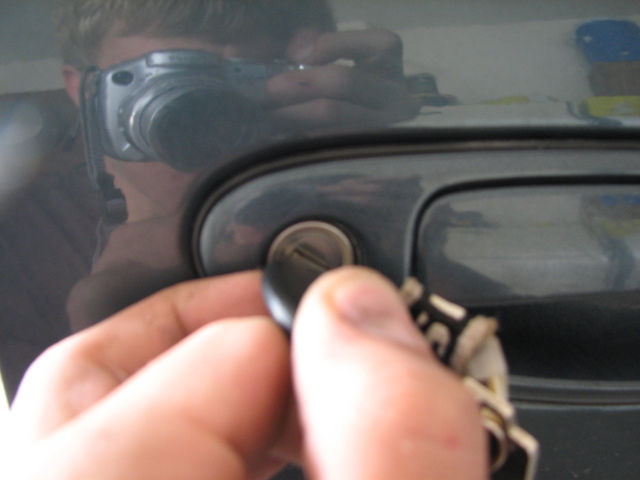
18. I found that the keyhole is almost impossible to push into the handle. I figured out the best way to do it is to take your key and insert it into the keyhole and turn it left. This locks the key in the hole, enabling you to pull it through the handle.

19. You can now thread and tighten the right nut, which will pull the keyhole all of the way through. Don’t forget to remove your key afterwards! Reinstall the left nut and insert the latch rod back into the handle.

20. MAKE SURE THE HANDLE WORKS before continuing work. If it doesn’t, recheck that the latch rod is installed correctly.

21. Reinstall the removed metal plate. Move the large metal bracket back upwards and reinstall all bolts. Don’t forget to re-fasten the white-ish yellow bar guide.

22. Double check that everything has been re-installed, then replace the weather covering. Make sure the sealant is applied so no water can get through.

23. Reinstall the door panel and all accessories.

24. You’re done with the front side!

REAR DOOR

Some steps here are similar to the front door procedure – if instructions are vague, refer to steps above.
1. Make sure the window is rolled up before beginning work.

2. Remove all accessories on the inner door panel. Remove door panel and set aside with accessories.

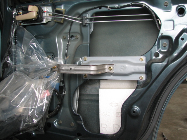
3. Peel away the majority of the weather covering – you’ll need a lot of room to work.

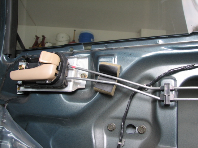
4. Remove the three bolts holding the inner handle in place.

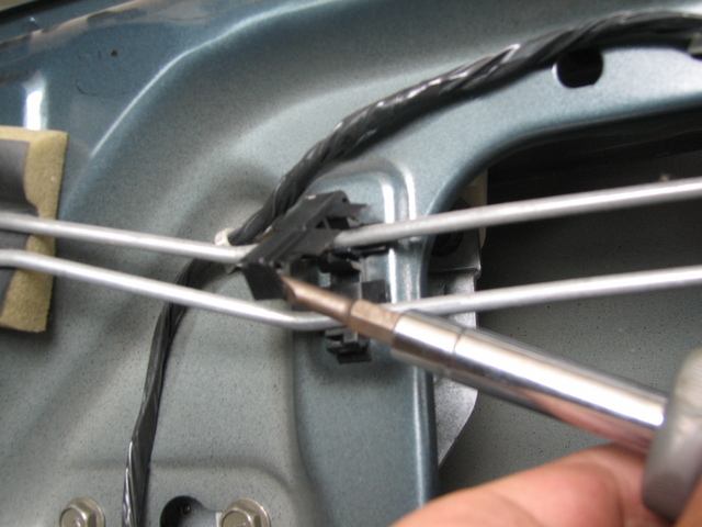
5. Unclip the black plastic guide and remove the bars.

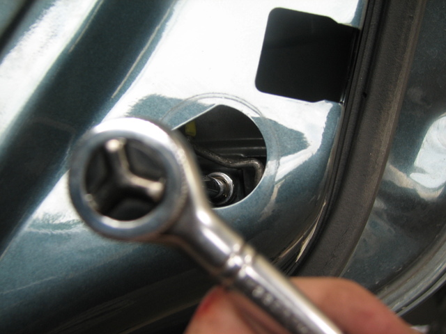
6. You can access the left nut holding the outer handle in place with the socket and extension. Remove it.

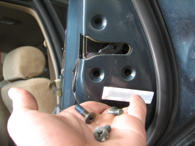
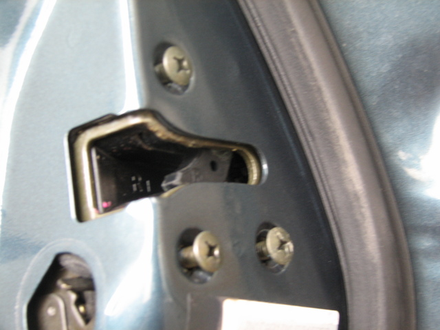
7. Remove the three screws holding the latch assembly on the side of the door.

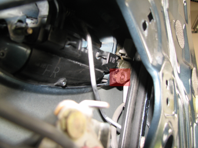
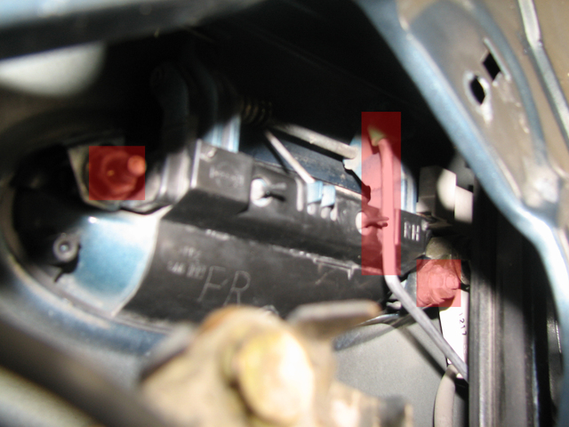
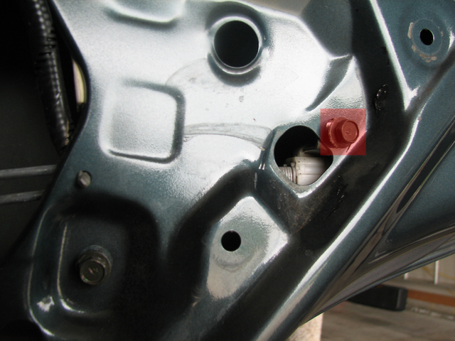
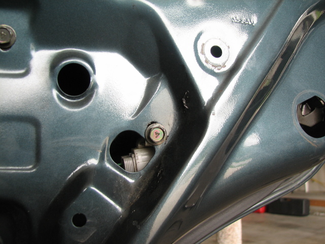
8. Remove the bolt highlighted in the below picture. The latch and rod assembly will come loose.

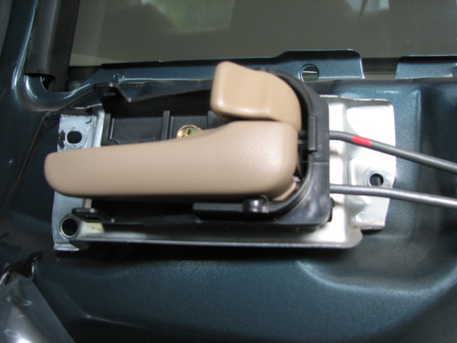
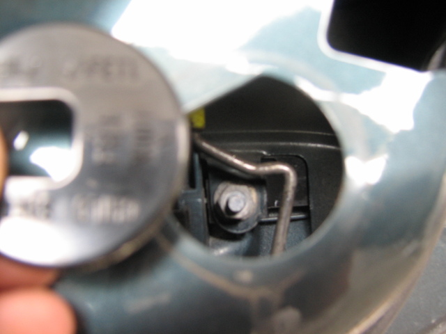
9. Remove the black “child safety” plastic piece. If the latch and rod assembly is moved to the side enough, the right nut for the handle will be visible through this hole. Remove it with the socket and extension.

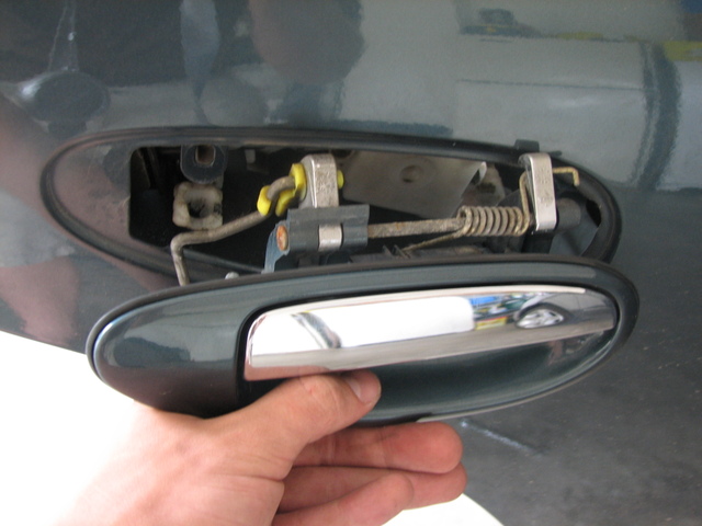
10. Remove the handle, with the latch rod, through the other side.

11. Examine the new handle. Make sure the handle operates. Make sure it contains the latch rod – if not, install the one from the old handle.

12. Fit the new handle into the door.

13. Reinstall the right nut through the child safety hole. Move the latch and rod assembly if needed to install the left nut.

14. Remove the 4 bolts holding in the large metal bracket and push it downwards, out of the way.

15. Reinstall this bolt into the assembly finger tight to hold the assembly in place.

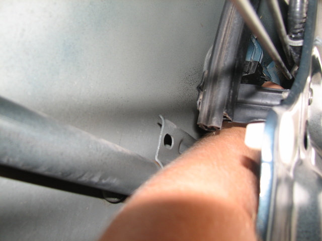
16. Here’s where it gets tricky. Remember the latch rod that goes from the outer handle to the latch and makes the outer handle work? That couldn’t be installed until now because the left and right nuts for the handle had to be installed first. This has to be done by feel, and it helps to have a long arm. Stick your arm along the bottom of the door, upwards until you feel the latch rod. Grab it, then feel around for a lever with a hole in it. Push this lever down and insert the rod into the hole. It’s too far back to get a picture, but feel around and you can get it.

The proper way to run your arm up there:

17. Once the latch rod is in place, reinstall the three screws for the latch.

18. MAKE SURE THE HANDLE WORKS before continuing work. If it doesn’t, recheck that the latch rod is installed correctly.

19. Re-tighten the bolt you hand-tightened. Replace the inner rods in the black keeper and snap it shut. Reinstall the three bolts for the inner handle. Replace the large metal bracket and install the 4 bolts. Make sure all screws and bolts are reinstalled and tight.

20. Replace the weather covering.

21. Reinstall the door panel and accessories.

22. You’re done with the rear side!

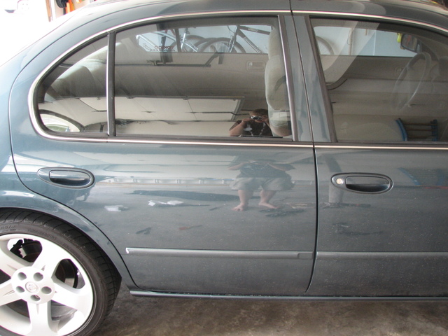
Before:

After:

Loading

Community Member Credit: Jeff Ketch

Installation was actually rather simple but did require some fabrication to get everything hooked up and working. Only a short piece of 3/4″ by 1/8″ steel and some aluminum angle were needed for mounting everything. However, understand that horn kits don’t ship with wiring or connectors, so plan on making several trips to the Radio Shack to get what you need. I suggest 10 or 12 gauge wire (with an inline 20 amp fuse) for the compressor circuit, while any 14-16 gauge wire will handle the switching tasks. You’ll need to tap into the stock horn wiring for the switching.

I am going to try and explain the wiring.

  • The compressor has two connections. One female end on the compressor and the other end to relay #30. WIRE: female connectors at both ends.
  • The other compressor connection is ground (negative…frame of the car or run an open connector to the car batteries negative terminal).
    WIRE: female one end and open or circle connector on the other side.
  • Relay #85 to ground (negative…frame or negative battery terminal)
    WIRE: Female connector on one end and open or circle connector on the other side.
  • Relay #86 gets a female connector and the other end is a male that plugs into the stock horn connector. The stock horn is in front of the radiator (looks like a 3″ diameter disk).
  • Relay #87 gets a female connector for the relay and the other end goes to the positive battery terminal( open loop connector. Take off the nut on the battery and put the connector between it).

Relay numbers:

  • 85: Ground
  • 86: Stock horn switching
  • 87: Hot lead that runs to the battery terminal (POSITIVE).
  • 30: Hot lead running to the compressor.

Short cut for Maximas:

The relay is not necessary for the air horns to work.

  • Plug a male connector into the stock horn switching, plug the other end of the stock horn switching into the bottom of the compressor (positive)
  • The compressor has one more connection (negative), the negative to the compressor and the other end to the ground (car frame)

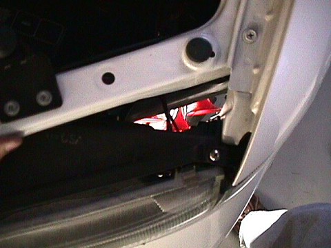
This picture is taken to show where the horns are installed. We’re looking down on top of the driver’s side headlight, and you can see the front of the horns light up by a drop light in the space in front of the wheel inside the fender.

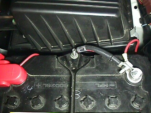
Here is the wiring that goes to the battery. Since the battery was so close, we didn’t bother wiring to a ground bolt. We used 12 gauge wire.

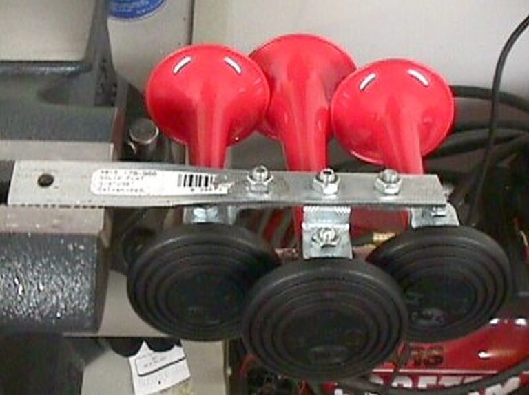
The horns are mounted inside the drivers side front fender, behind the fog light. Here is a picture showing the horns mounted to the strip of metal. We picked up the metal at Home Depot, they’ve got tons of it. Doesn’t have to be 3/4″ x 1/8″, anything in that range will do. Underneath the metal, you can see the support bracket that connects to the fender. This comes with the Maxima. It is too thin and also has a shape to it that wouldn’t allow mounting the horns to it.

You can also see the relay is attached using the same bolt as the horn all the way to the right. The top and bottom terminals connect to the compressor, thus the heavy 12 gauge wiring. The other wires tap into the stock horn wiring to control the relay, and don’t have to be heavy duty, so I used some extra speaker wire I had laying around.

You are looking top down…between the radiator and the front grille. The picture shows the stock horn switch (black) and the wire used to tap into the stock horn. By tapping into the stock horn for switching when your factory alarm goes off it uses the air horns. Also disconnect the other stock horn that is in the engine bay on the left side.

Here’s another view of the above picture, taken from farther out. You can easily see the fender support brace here. Take the 10mm bolt out, then put the horn bracket between the support brace and the frame. This is also where I ran the ground for the stock horn.

Here is another view of how we mounted the horns.

Yet another angle. These pictures should be clear enough so that you can understand how to do this on your own.

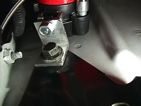
This picture is taken from the floor, looking up to see where the compressor is mounted. We used a short section of 1 1/4″ x 1 1/4″ aluminum angle to mount the compressor to the top of the shipping tie down hooks which are attached to the frame via three heavy bolts.

Here is a close-up of the aluminum angle we used to mount the compressor. Again, this was obtained from Home Depot, but be warned… the shortest length they sell is 8 feet… and you only need about an inch or so to make this bracket. If you felt adventurous, you could make the bracket by bending a piece of the same 3/4″ x 1/8″ steel that the horns mounted to.

Finally, here is a good shot of the area where the compressor mounts. The horns are at the top of the picture, the compressor mount is below the rightmost horn, and the driver’s side fog light is at the bottom of the picture.

Finished Product

Loading

Community Member Credit: justmax

Basically this is a mod that short-circuits the Cruise control relay that requires you to turn on the toggle switch on your dash to the left of the steering column…

What you’ll need:

1. A couple of inches of 14-gauge wire (16 or 18 might work, but I didn’t want to risk the wire melting)

2. A couple of crimp-on flat spade connectors

What to do:

Attach the spade connectors to either end of your wire, like this:

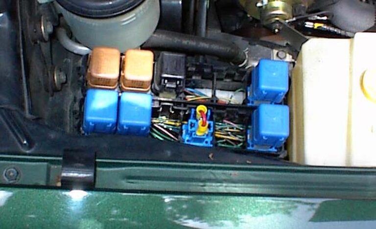
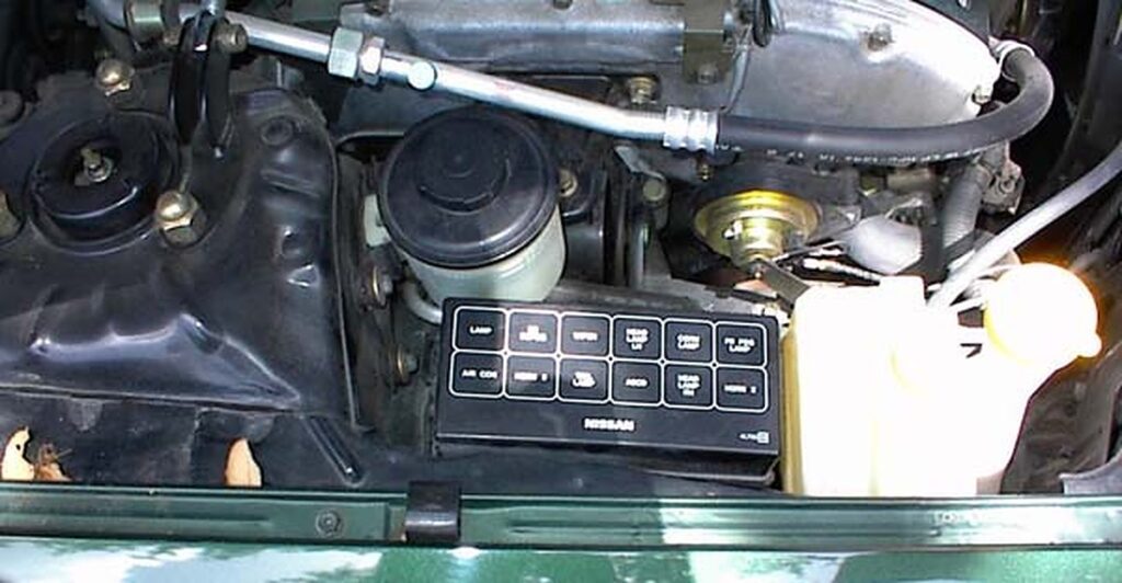
Open up the relay box on the passenger side of the engine bay, you’re looking for the slot that has ASCD (Automatic Speed Control (Device):

Remove the ASCD relay from its slot (a small flat-head screwdriver will help you with the clip that holds it in). Now insert your wire into the connection that is perpendicular to the other 3, and the connection opposite that, like this:

Put the cover back on the relay box and put your unused relay away, cuz you’re done. Now the cruise control will be on whenever the car is on.

Loading

Community Member Credit: Sexima

Things you need to BUY:

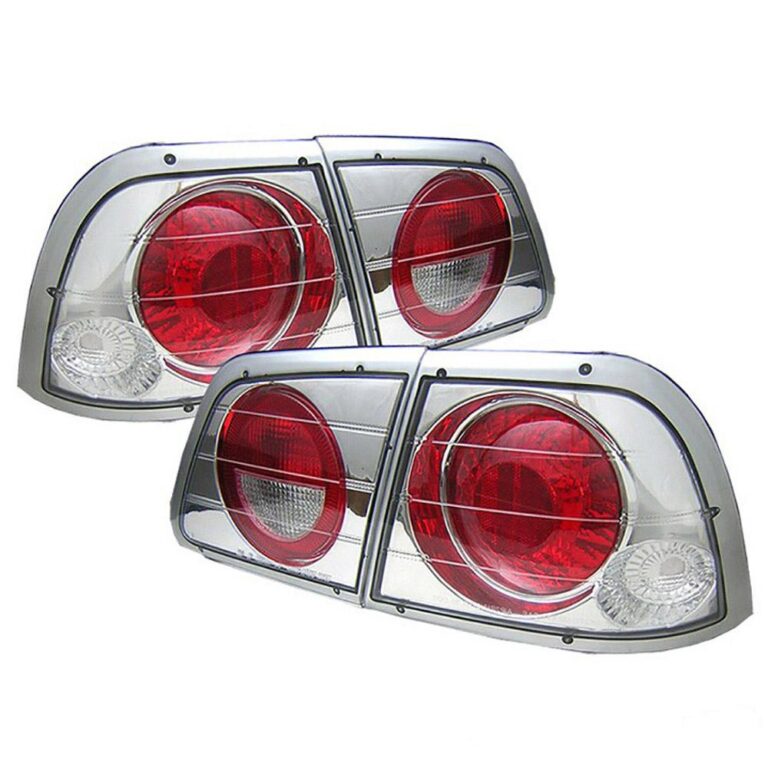
  • Altezzas (Search eBay / Google)
  • Spray Paint & clear coat & primer from Paintscratch.com *tri-coat if needed*
  • some type of Circle shape that will cover up the red spots in Altezza’s
  • Goof Off or Goo Gone product *Home Depot*

Instructions

1. View your Altezza’s and enjoy it while it lasts.

2. With the circle shape (I took bowls and matched them up on the Altezza’s and then draw the shape on paper. I taped the front side so it doesn’t absorb the paint in. Then taped them to the Altezza’s making sure no paint will go through. Then put it on the Altezza lights.

*Note*: I didn’t cover up the side marker because I didn’t need them You may cover them if you want to.

3. Spray a thin layer or two of the primer. Try to get a primer that is close to your car color. Let it dry.

4. Use the paint you got from paintscratch.com and spray them layer by layer. The best is to put a thin layer on, come back in 10 minutes, put another thin layer. And repeat this step till you have the whole thing covered. Try putting about 10 layers on.

5. Wait till it dries… Let it dry for about 3 hours.

6. Clearcoat *or tri-coat if you needed* with layers. about 4-8?Whatever floats your boat.

7. Let it dry for an hour or so… after it is dry, CAREFULLY take off the circle thing that you used. you don’t want hand marks on that thing…

8. You will see some parts that you painted that you don’t want. Simply wipe them off with Goof Off product. Do not use too much of it, it will leave little marks. Don’t try to make it too perfect or it will look stupid at the end.

9. Go outside and clear coat the WHOLE THING and it will leave you one shiny
skyline’s ass!!

Finished Product

NightTime

DayTime

The originator of this Style Tails Pic…


Loading