Category

my4thgen 95-99

Category

Community Member Credit: D.Mason

Tools Needed:

  • 8mm Deep Socket
  • Phillips head screw driver
  • Flat head screw driver
  • Heat Gun
  • A metal ruler or some sort of straight edge
  • A rotary tool with a cutting blade or soldering iron
  • Gloves
  • Acrylic fluorescent light cover sheet (Home Depot, Lowes, OSH)
  • Pliers
  • Hammer
  • Knife or prying tool

Estimated time: 3 hours

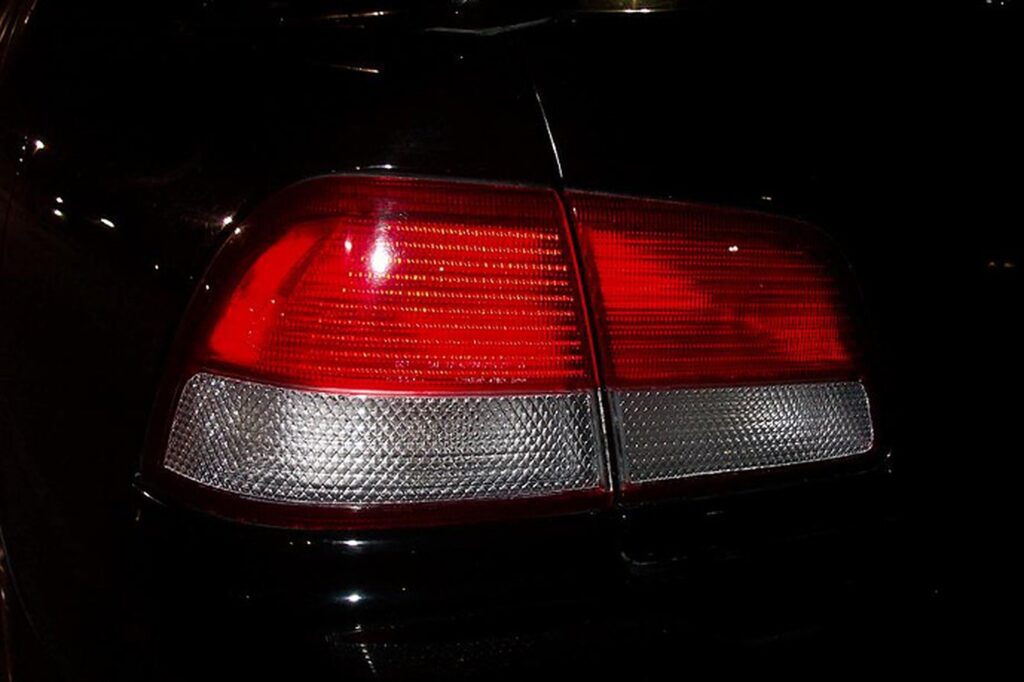
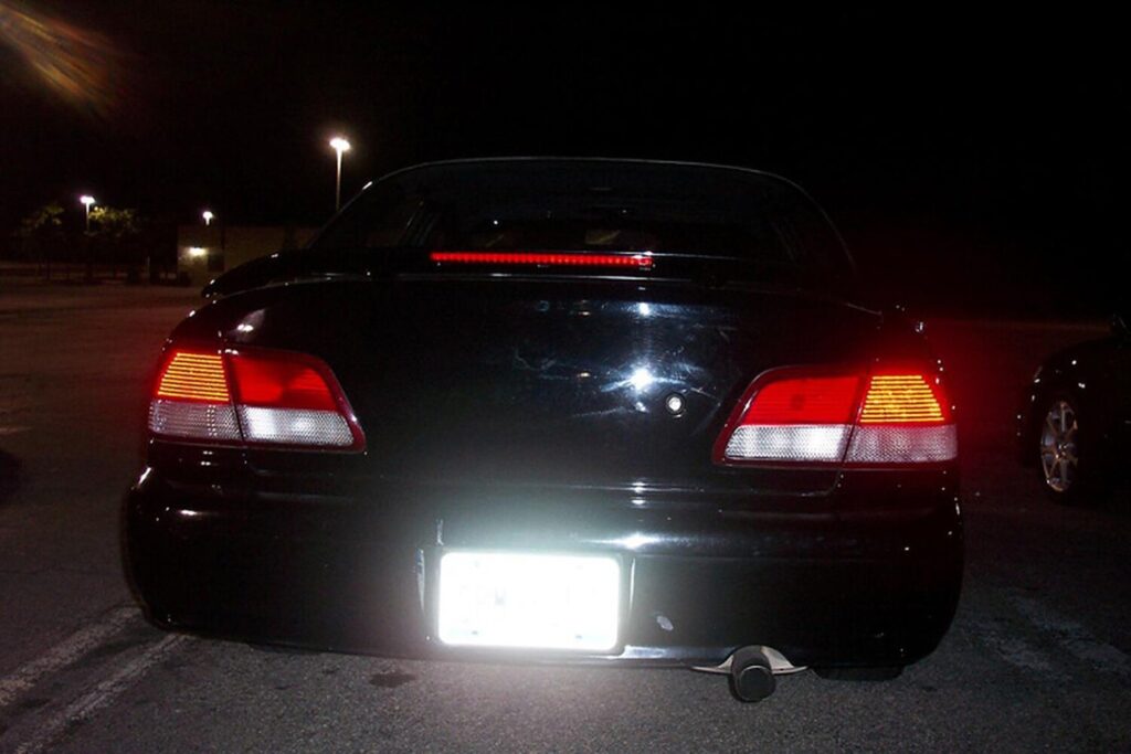
Note: These were the best picture we could get on this one.

The first step in modifying your taillights is to remove the taillight from the vehicle. Begin by removing the interior lining in the trunk. Some of the tabs that hold the lining in require a flat head screwdriver while others come off with a Phillips screwdriver. There are 2 plugs that need to be unplugged from the tail light. They both have white connectors. There are also some plastic pieces that hold all of the wiring to the nut. These may be tough to yank off. I used a pair of pliers to pull them off. There are 4 8mm nuts that hold the taillight in. Remove these using an 8mm deep socket. The only thing holding the taillight is some black sticky adhesive. There are a few ways to get the taillight out. One method is to gently heat up the adhesive using the heat gun so that the adhesive softens. Then push on the taillight. Another way is to gently tap on the 4 studs that hold the taillight in the vehicle. Lastly you can push the taillight out of you are strong enough. Place the bottom of your palm on the flat part of the taillight and push hard! Be careful of the adhesive so that it does not get on your hands or the taillight.
1. Remove the 5 small black Phillips screws that are located around the taillight.
2. To separate the taillight lens from the housing you will need to heat up the glue that holds it together. It will most likely take at least two passes on each side of the taillight to get the glue warm enough.
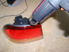
3. Some heat guns only have a ‘low’ and ‘high’ setting. This particular one has 10 different setting. As you can see a setting of 8 was used. The key is to not overheat any one particular spot because it will melt the plastic housing or taillight lens.
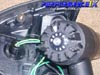
4. Pick one side to begin with and hold the heat gun about 1″ away from the black housing. DO NOT HEAT UP THE TAILLIGHT LENS AT ALL! It will begin to fry like an egg. Heat up that spot for 7-10 seconds. Do this on every spot on this particular side of the taillight.
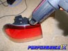
5. Working your way slowly around the tail will ensure no damage to the housing or lens. This is the most time consuming step in the entire process.
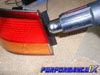
6. One you have gone around the taillight twice, it may be soft enough to pry open. Using a knife or some type of prying tool, try to pry on a corner of the taillight and see if it gives. If it does, slowly pry the tail light open until it separates from the lens. If the glue still seems cold, apply some more heat with the heat gun.
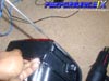
7. Be Careful of the lens beginning to separated.
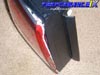
8. The lens is completely separated. Make sure that the glue does not stock to the outside of the lens. It’s quite messy.
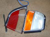
9. Use the knife or pry tool to remove the orange lens. Use some heat if necessary.
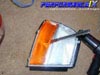
10. Cutting the acrylic lens can be a bit frustrating. Don’t let it get you down. Here are some tips on cutting the piece out. Some people use the orange and red lens and trace it out on the acrylic sheet. Others try to make a paper template that will fit in the taillight lens and then use that template to cut the acrylic. Some tools that can be used to cut the acrylic lens are a rotary tool, acrylic cutter, or a soldering iron.
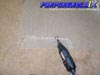
11. Once the lens is cut, you need to wedge it into the taillight lens. Use a bit of heat the curve the lens. Use very little heat or the lens will melt!
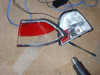
12. Removing the red lens is up to you. I chose to remove it. Some don’t. Your call. Simply remove the Phillips screw.
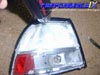
13. Once the new lens is in, you are ready to put the taillight back together. Reheat the glue until it is soft and then put the lens into the housing. Hold it tight for about 15-20 seconds so that it seals properly. Put the screws right back in so that it helps seal the taillight the way it originally was.
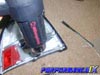
14. Isn’t that beautiful! One note. There is a size #194 wedge bulb behind where that small red lens was. That light is just a driving light that turns on with one turn on the light stalk. I chose to remove the bulb so that it wouldn’t show. Again, user discretion. Put the taillight back in and re-connect everything. Put back lining too!
Loading

Community Member Credit: gtr_rider

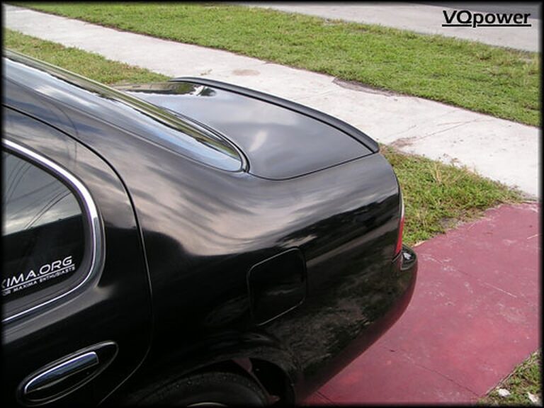
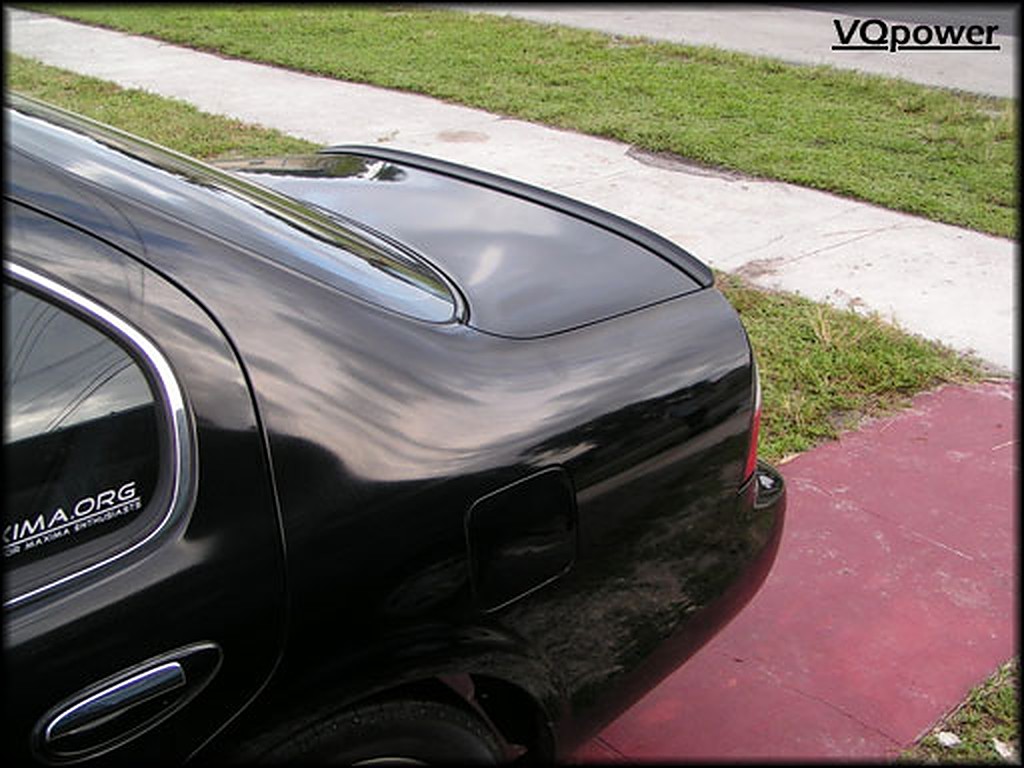
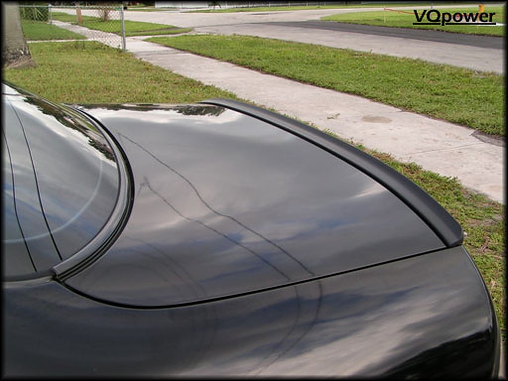
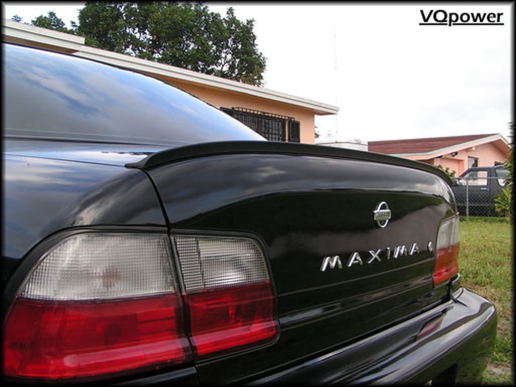
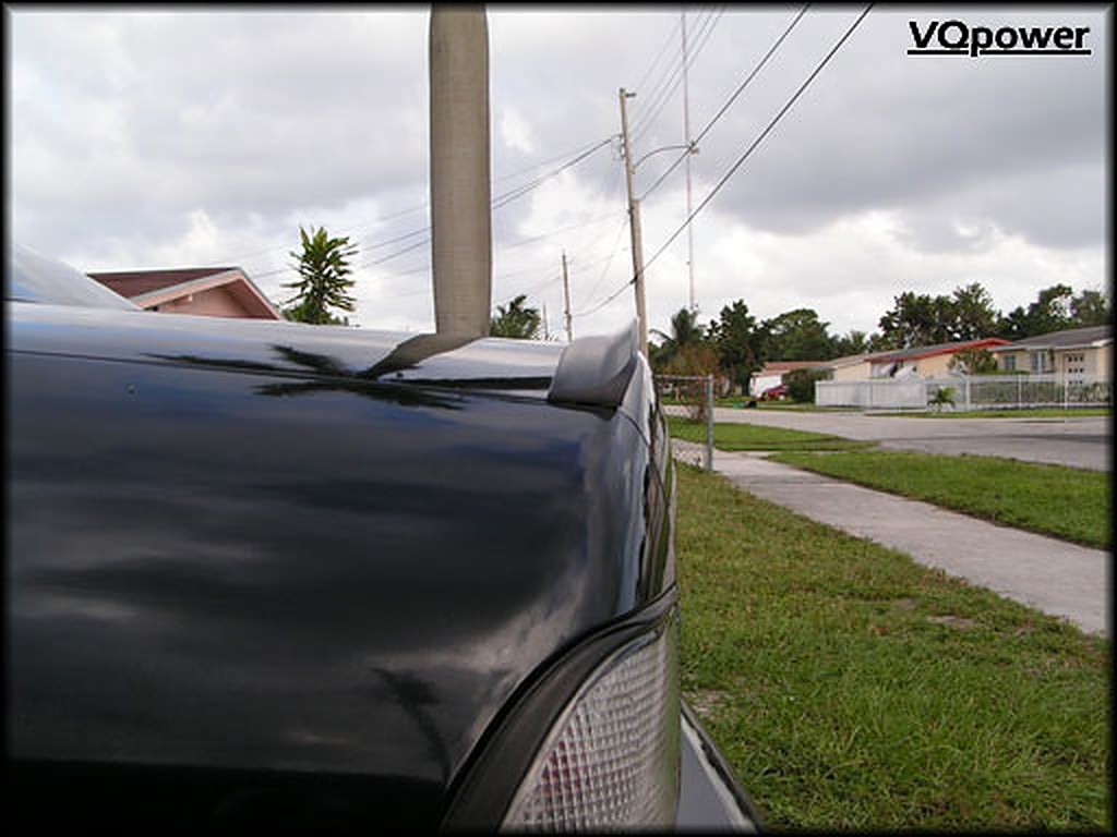
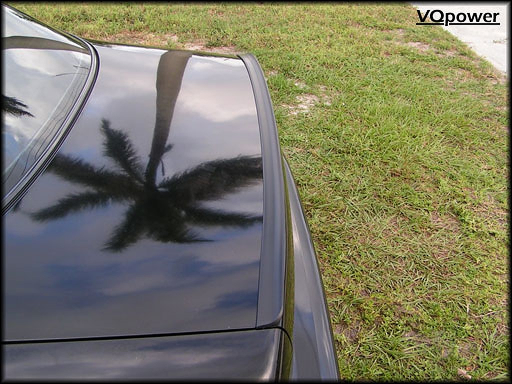
I was able to get a hold of an A32 lip spoiler which is really designed for the 1st gen I30. I was going to give it a try and put it on my A32 Maxima(1995-1999). To my surprised when it came to my door, it was way more flexible than I imagined it to be. That making it a plus because install would be more easier to perform. I put it flush with the very edge of the trunk, and aligned each corner to extend a little past the edge(slightly longer on each side). Masked off the line on the trunk for later placement, rubbed some alcohol along the area and put the lip down. Looks amazing, and I encourage those spoiler-less Maxima owners to pick one up.


Loading

Community Member Credit: nadir_s

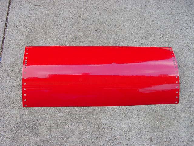
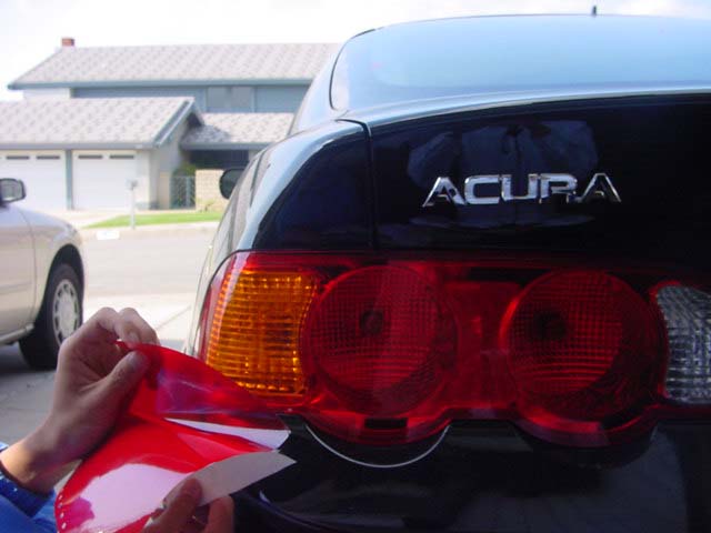
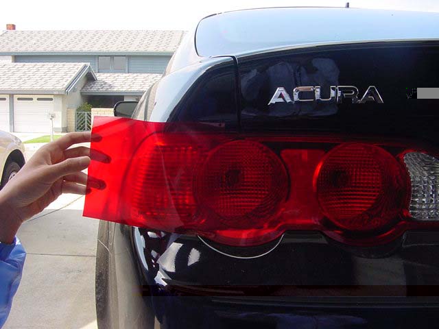
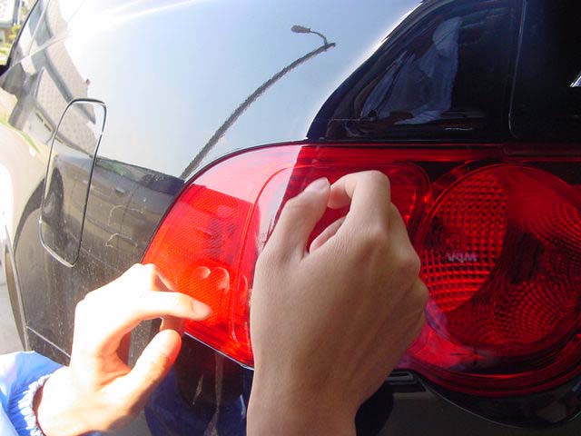
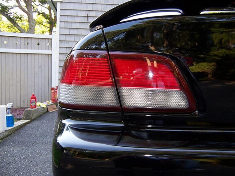
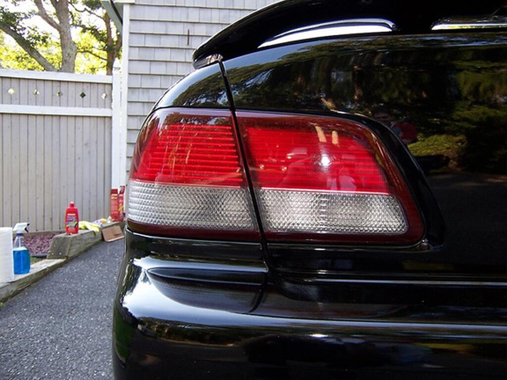
I’ve explained this a lot of times but i thought I’d write a clean explanation on how to “red-out” your tails. This really goes out to all the 95/96 owners who want to at least get rid of the ugly ambers on their tails. This process requires some effort but is worth it in the end. There are 2 ways to red them out… using red tape or painting them. This is how to use the tape. Of course the real red/clears look great but this is a pretty simple $3 cosmetic mod!

Things you need:

  • HeatGun or BlowDryer (heatgun works better)
  • Soapy water (water mixed w/ dishwasher fluid works)
  • Red Translucent Vinyl Tape (can be purchased at a hobby store or from Oracal.com – 8300 High Performance
  • Translucent (link is external)… one sheet would be enough to cover both ambers; $3 per sheet)
  • something flat and hard… a credit card works perfect

Procedures:

1. Wash/Clean both tails so that there isn’t any dirt on them

2. Now, apply LOTS of soapy water on the tails… let it run down, it doesn’t matter, but they need to be wet as you apply the tape. The reason for the soapy water is to avoid any air bubbles or having the tape annoyingly stick onto the surface where u don’t want it to be.
3. Now place the tape on the ambers and position it. With the water under the tape, you will be able to move the tape and adjust it properly.

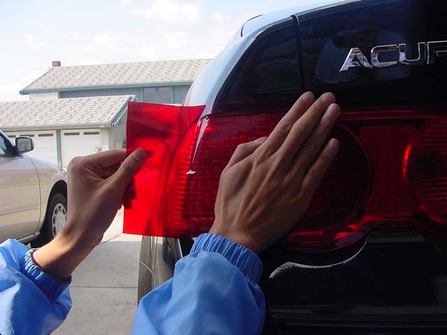
4. After adjusting it, use the credit card to squeeze out the water underneath. Start from the middle, then move outwards. Keep scraping the top of the tape so that the water underneath will squeeze out from the ends of the tape. Don’t worry, the adhesive will still be 100% sticky.

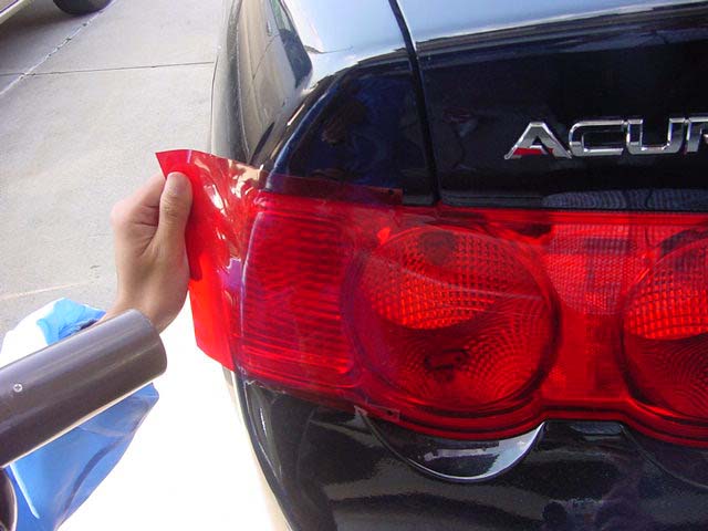
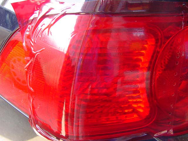
5. Now that you’ve squeezed out as much as u can on the most flat surface and the tape is stuck to the ambers, you will realize that u have to do the outwards of the ambers where they curve. For this to be done properly, use your heatgun/blowdryer to heat the tape so that it “melts” or become softer and stretchable.

6. As you heat up the curved parts of the tape, stretch the tape out as hard as you can w/o ripping it hopefully to wrap around the curve and not form any air bubbles. CAUTION: Don’t burn your fingers!

7. After doing a satisfactory job w/ the tape stuck to the ambers, use an exact-o knife or razor to cut the excess tape off. CAUTION: Don’t cut yourself in this process.

Voila! No more ambers.

As you read this instructions, you may start to realize this is EXACTLY how tinting windows are done. Basically you are doing a tint job on your ambers. Good luck!

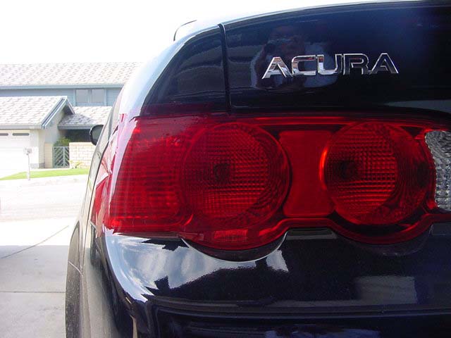
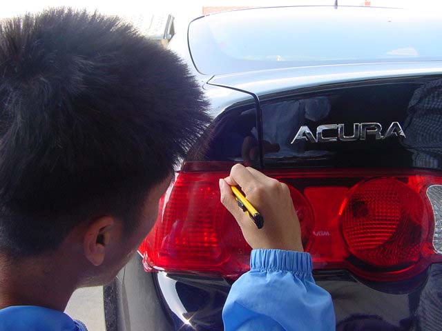
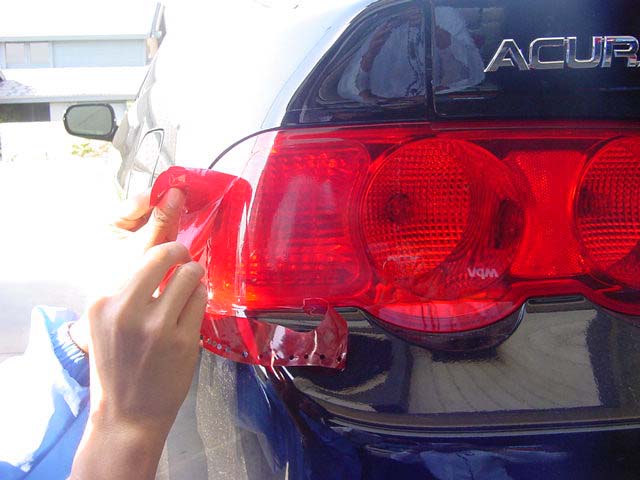
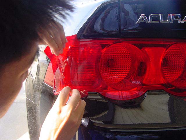
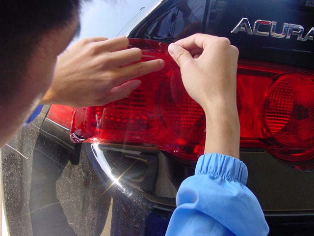
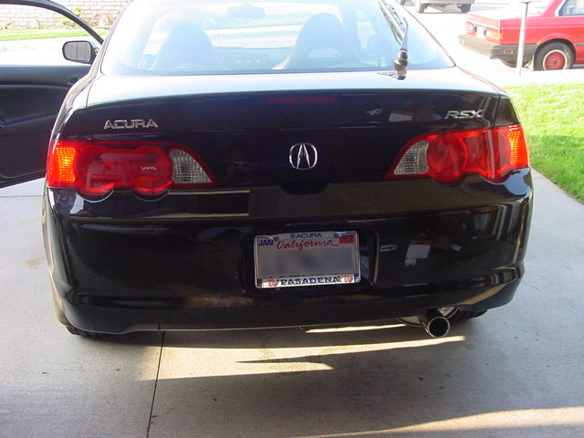
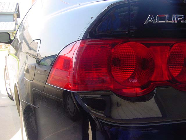
ACURA RSX RED OUT TAILLIGHT INSTALLATION

Tools Required

  • Xacto Knife
  • Hair Dryer
  • Red Transparent Vinyl

Step One

Get your sheet of transparent red vinyl.


Step Two

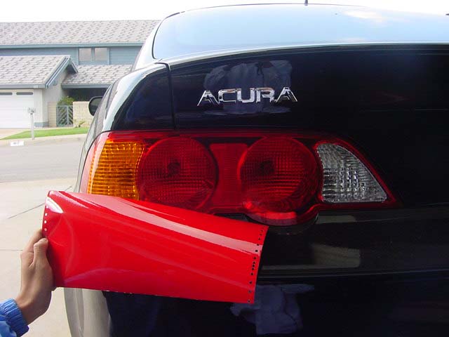
Put the sheet up to the signal light and see how much you will need.


Step Three

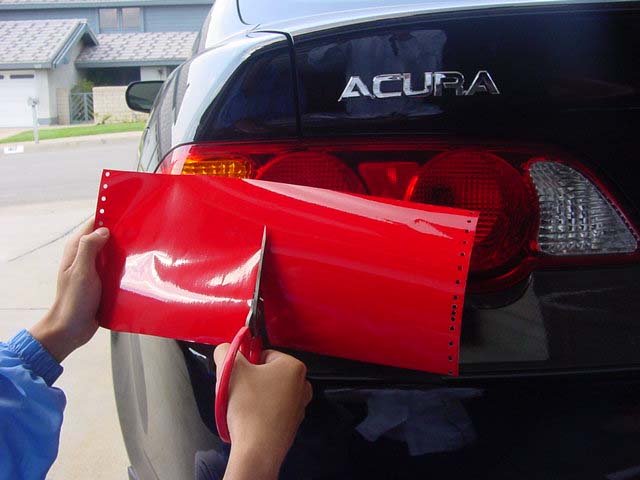
Start cutting the vinyl so u have enough for one side.


Step Four

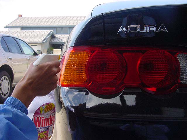
Mix water and dishwashing liquid in a spray bottle and spray onto the tail lights.


Step Five

Peel off the vinyl, exposing its sticky side.


Step Six

Apply the vinyl flat and parallel to the tail light.


Step Seven

Flatten the edge out as much as possible, while pushing outwards towards the borders of the vinyl. Doing this will push out all of the soap water underneath. If you fail to push out most of the water, theirs a chance of small bubbles forming. Now do the same to the sides of the signals. This part is a bit trickier because the vinyl might wrinkle a bit on the sides.


Step Eight

This step is optional, but it is highly recommend. This will help get rid of wrinkles, giving you a smoother, cleaner look. Use a blow dryer and aim it towards the edge of the vinyl. You will notice that the vinyl quickly becomes more flexible. Use this to your advantage. Pull the vinyl outwards and stretch it so that it is taut (not slacked.) And use flatten it down. It helps to have another person help u at this stage, but not necessary. The vinyl should be on nice and smooth over the amber signal area.


Step Nine

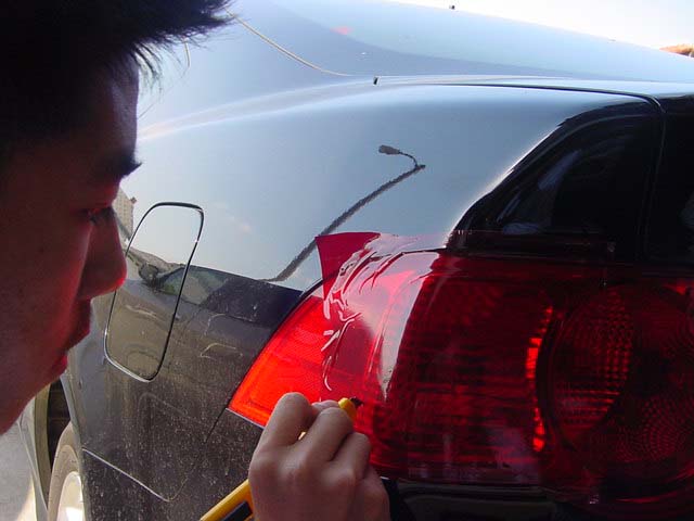
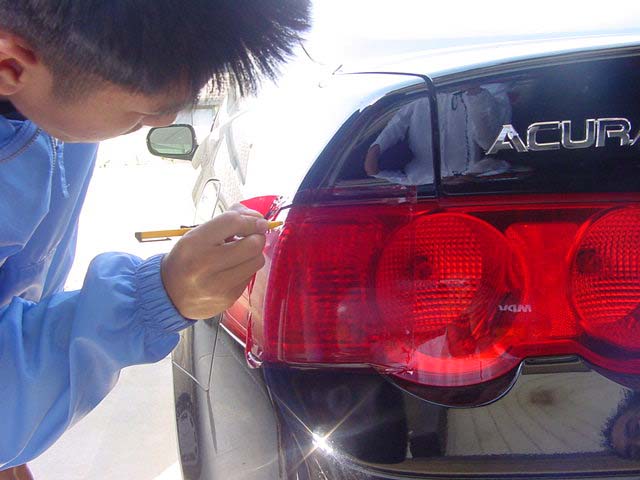
With your exacto blade, begin lightly tracing the shape of the signal. You should be able to see the shape through the vinyl.


Step Ten

Once you have traced the entire outline of the amber tail light, start peeling off the excess vinyl.


Step Eleven

Once you have gotten rid of all the excess vinyl, flattening it out again with your hand to get rid of any left over water/bubbles.


Step Twelve

Wait about 5-10 minutes to ensure its dry.


If you ever want it back, all you have to do is peel it off. The vinyl is very strong and will withstand the weather and car washes.

Loading

Community Member Credit: RyanT35

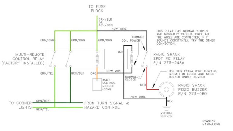
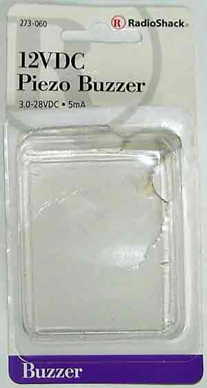
Make your 4th gen Maxima beep when the alarm is turned on for less than $10. If you don’t like to watch the alarm turn on but would rather hear it turn on then this mod is for you.

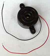
Basically, there’s relay (multi-remote control relay) in the trunk which flashes the corner lights when the alarm is turned on. We’re going to buy a cheap $3 buzzer, another $4 relay, and attach it to this MCR relay so that the car beeps. Hear it for yourself: buzzer.wav

The mod should take less than 1 hour to perform. Here’s the schematic:

1. Go to Radio Shack and buy item # 273-060 (buzzer) and item # 275-248A (mini-relay).

2. Remove the Lamp and BCM fuses before starting work. The Lamp fuse is located inside the car. The BCM fuse is located in the engine bay.

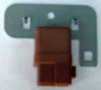
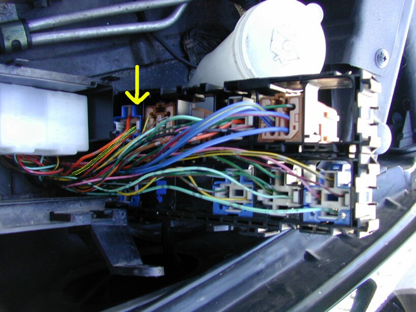
3. Locate the Multi-Remote Control Relay in the trunk. Start by removing the plastic cover above the trunk latch. The relay is the brown rectangle in the picture below:

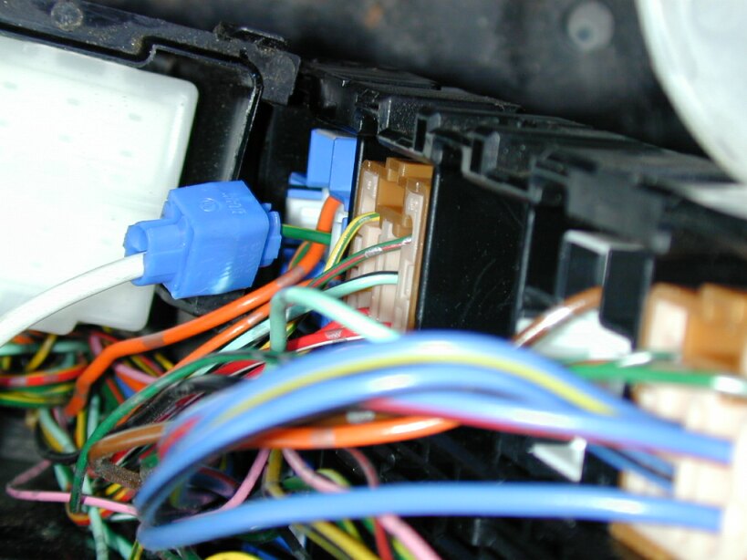
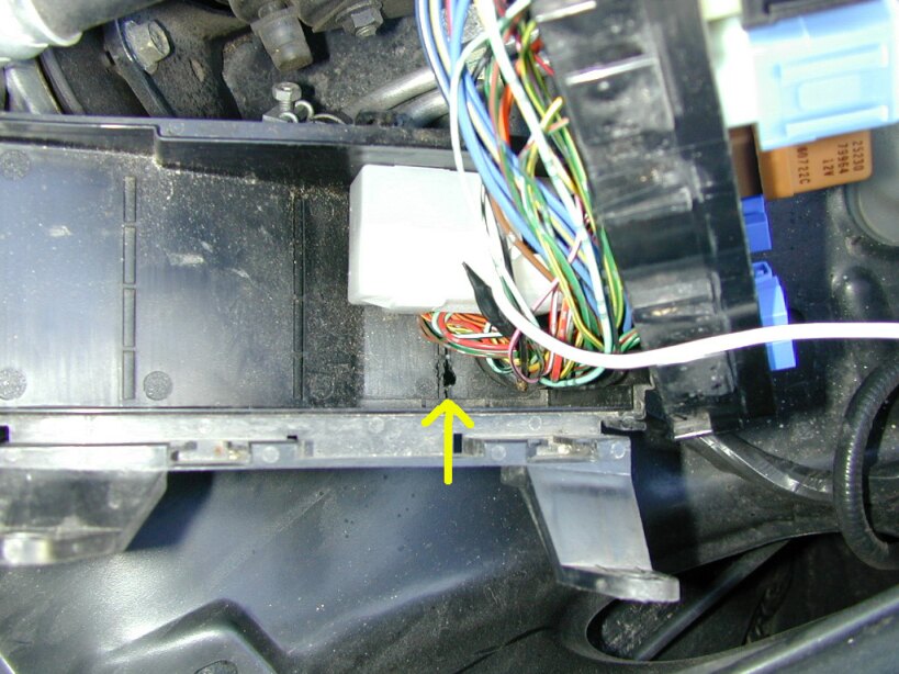
4. Remove the MCR relay and it’s mounting bracket. There’s a mounting tab for another relay so I used this space to mount the new relay and buzzer. I also used connectors to make the mod removable (although this could move the budget into the $10-$15 range).

5. Splice into the “Green/Orange” wire (orange is the strip color) for power (+12v). There’s 3 of these wires so just choose one. Next, splice into the orange wire (solid color) for the sink from the BCM (ground).

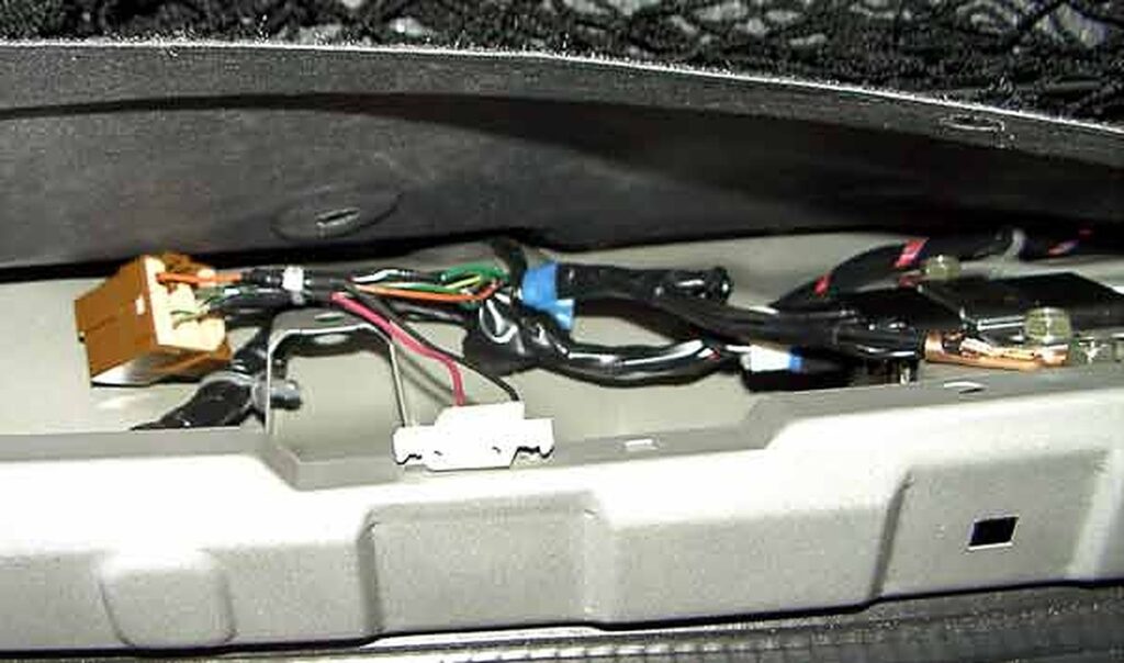
6. Connect and test (refer to the schematic for details). The final setup looks like the picture below. Turn on the alarm and it should beep twice. Note: don’t splice your buzzer into the G/B or G/Y wires (to save on the extra relay) unless you want to beep while turning…

Loading

Community Member Credit: Dallas Nissan Enthusiasts

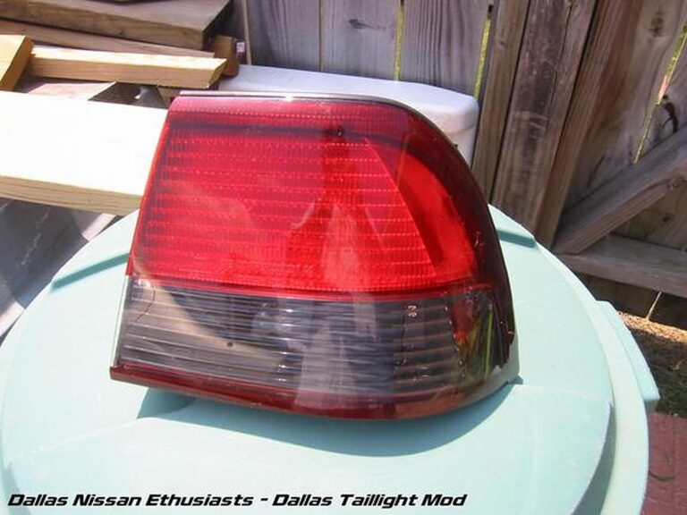
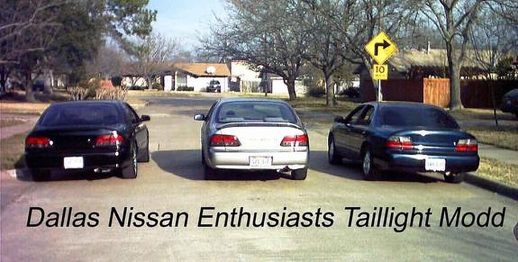
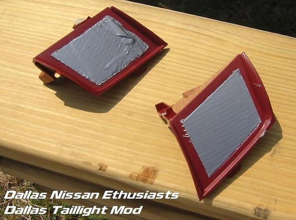
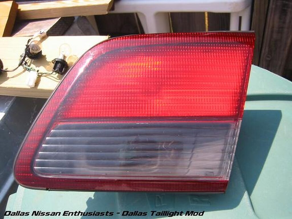
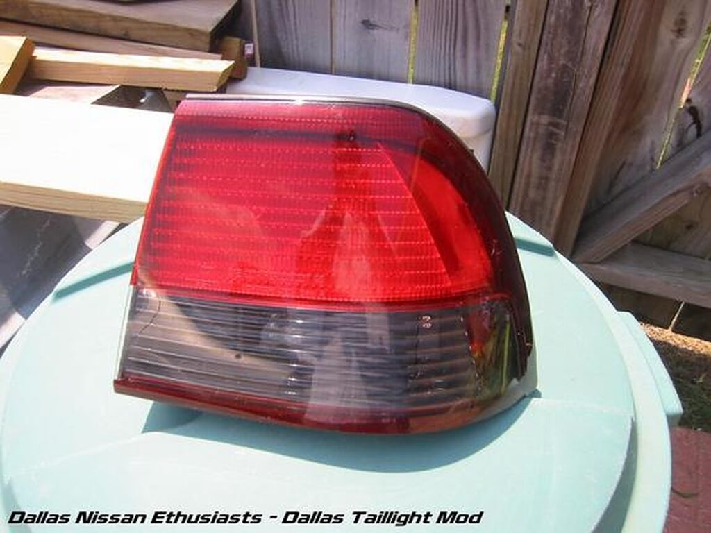
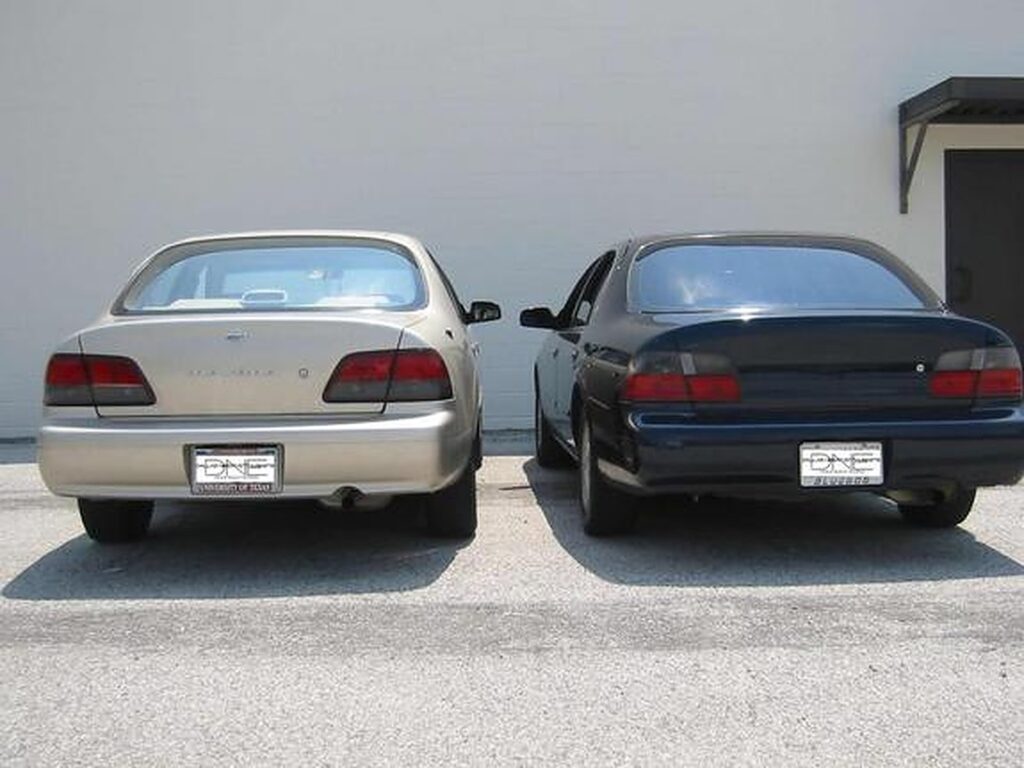
This write-up below is a step-by-step set of instructions with pictures on how to do the Dallas Taillight Mod. It is similar to the 97-99 Red/Clear mod but with a twist.

Things you will need:

  1. Good size flat head screwdriver
  2. 8mm deep socket
  3. Needle nose pliers
  4. Heat Gun (not necessary but helps a lot)
  5. Can of high temperature flat black spray paint. (AutoZone)

This is the paint we used.

We will start with the reverse light assemblies.

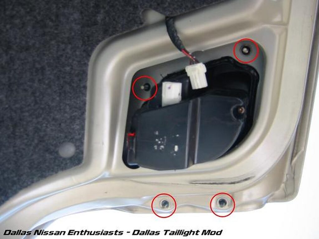
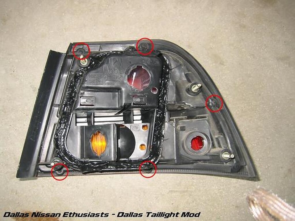
First, unscrew the 4 8mm nuts that hold the reverse light assembly onto the trunk lid. All 4 are highlighted by the red circles. Once these nuts are removed, remove the screw that holds the plastic cover on the back. You should now be able to pull the small plastic cover off which hides the bulbs and sockets. Go ahead and unplug the wiring harness located at the top of the pic.

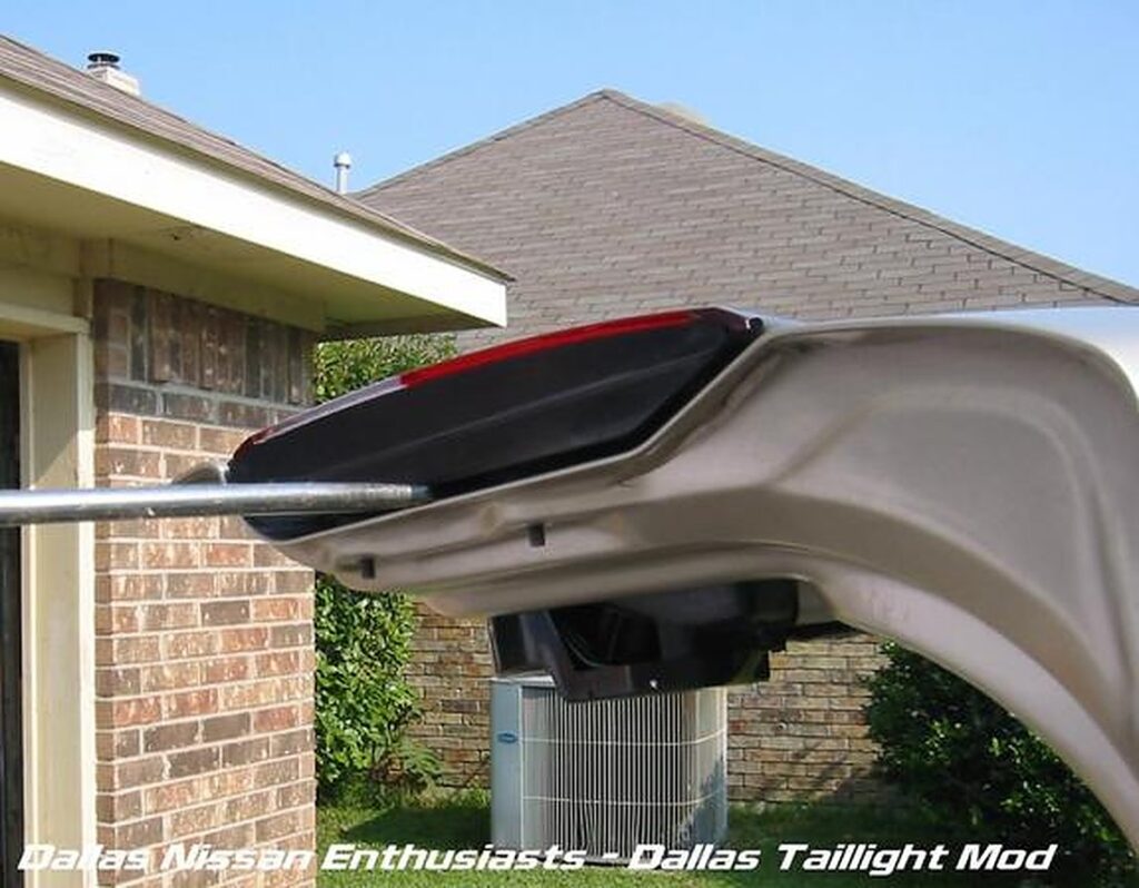
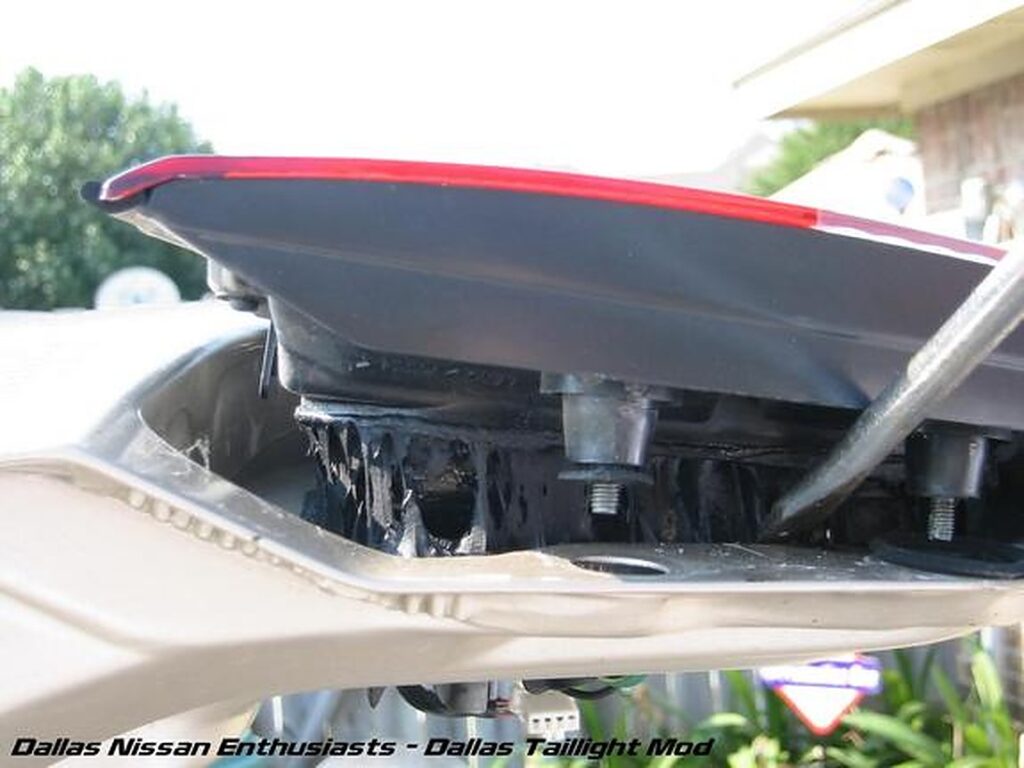
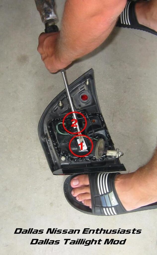
You can now take the flat head screw driver and stick it in between the taillight assembly and trunk lid (as shown on the left) and pry it up (as shown on the right). As it comes up, you can use the heat gun to heat that black goo up which will make it easier to pull it off and make the assembly cleaner once it is off.

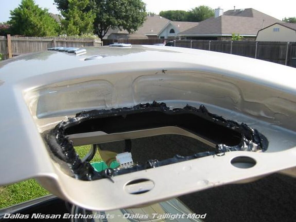
Once you have pried that end up, you can use your hands and lift the assembly straight out of the trunk lid.

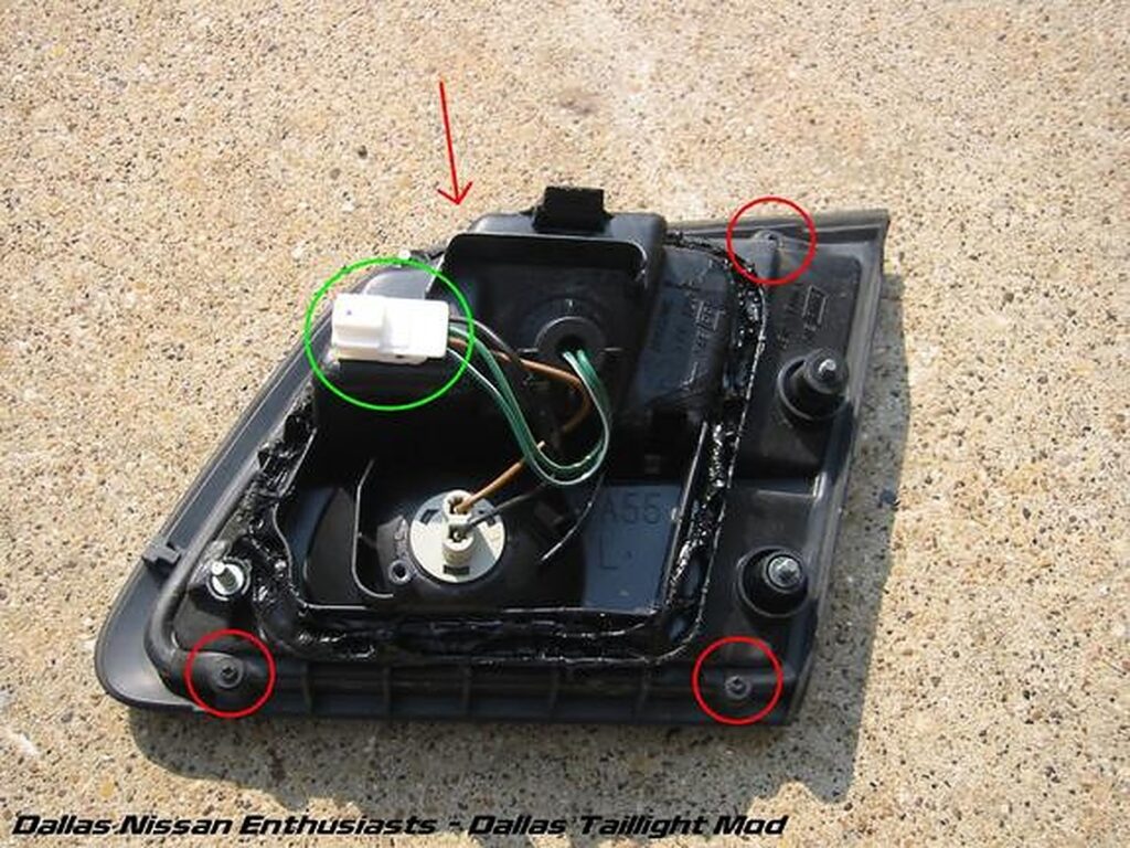
Now that the reverse tail assembly is out, you need to remove the lighting wiring plug from the assembly and remove the four screws. The plug is marked by the green circle and the four screws are marked by the red circles and the red arrow. Using the flat head you can pop the plug off by pushing on the plug from the ride side with a fair amount of force.

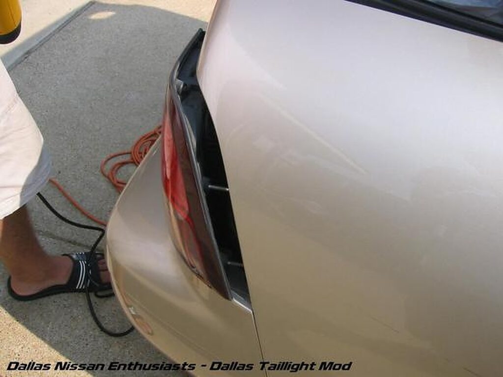
Now we can begin on the turn signal assemblies. Again, unscrew the four nuts which are marked by the red cirlces and the red arrow (didn’t get picture of all four). You will have to pull those white plastic things off the two inner bolts to remove those nuts. A set of needle nose pliers can help if you can’t pull them off with your hands. You can now use the screw driver again and pry from the trunk side, use the heat gun again if you want (makes things easier and cleaner), and pull the assembly straight out (as shown on the right).

For the side, there are two light harness plugs to be popped off (left) and 5 screws that you must remove (right). You can see I am using a big flat head screw driver and a very small sledge hammer to remove the plugs. This is overkill, but it was close, available, and it worked.

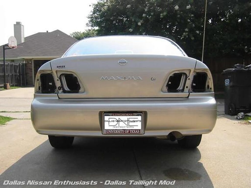
Your ride should kinda look like this now. Pretty huh?

Now with all the tails removed, all the screws removed from each assembly, and all the lighting wiring remove, we can go inside and begin the hard part.

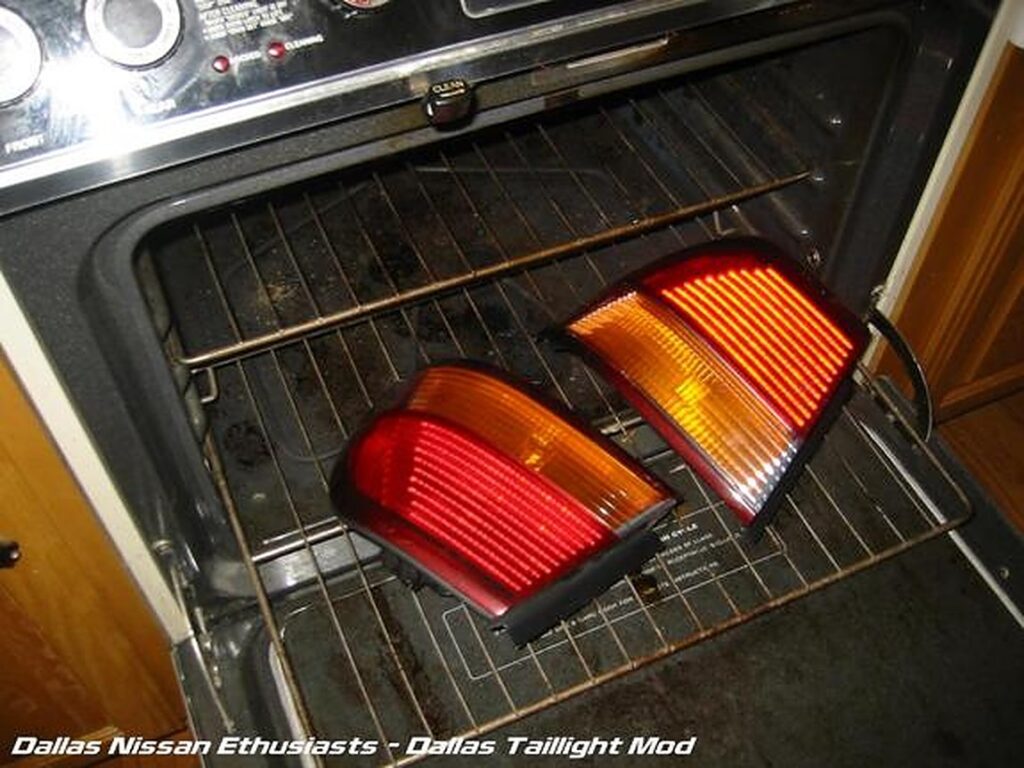
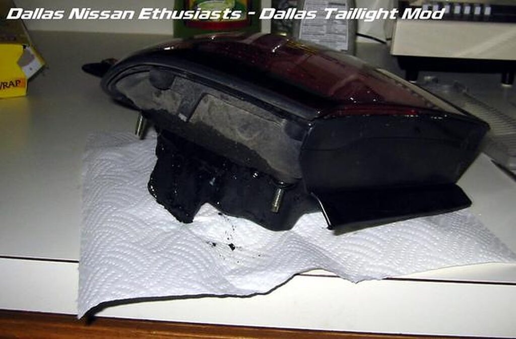
From this point, some people have chosen to sit with a heat gun and heat the edges of the assemblies but that seems to difficult to me, so I use the oven. Set your oven to 200 F degrees. Once the oven has heated up for a bit, place the reverse tail assemblies or the signal tail assemblies in the oven. We did the reverse first, but it doesn’t matter. The pic shows the signal tail assemblies on the lowest oven rack to really get them warm.

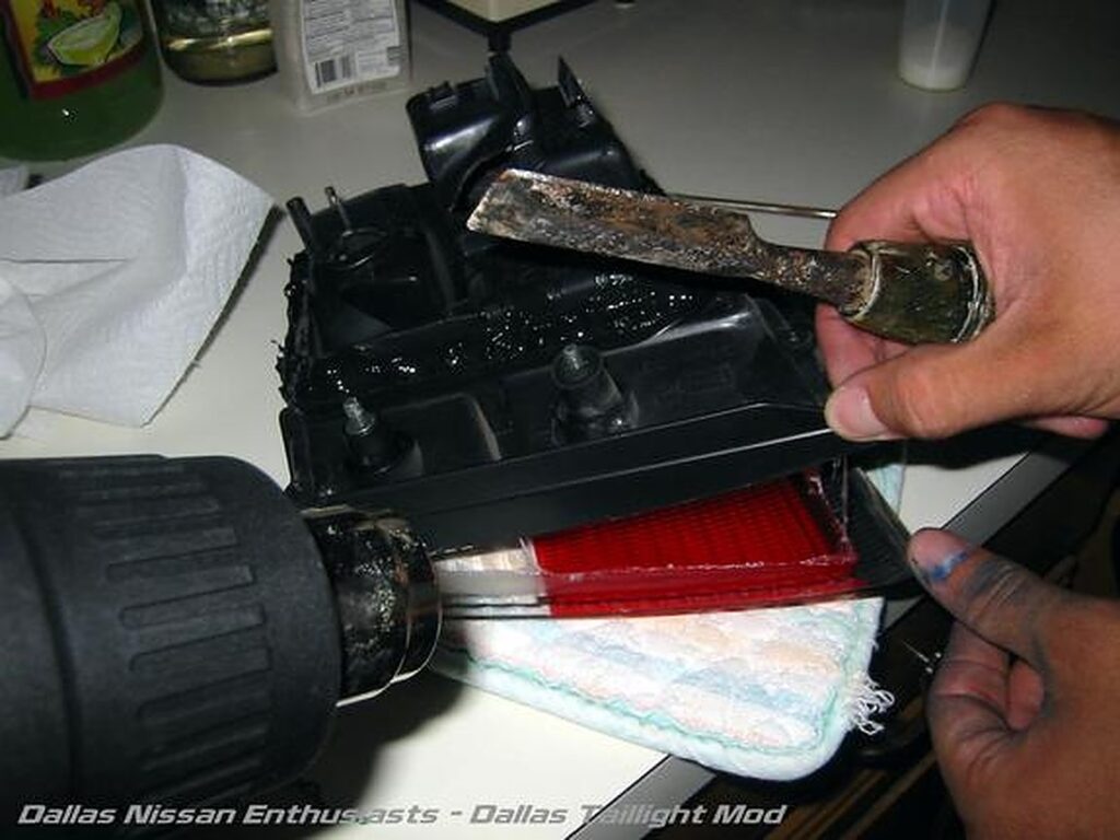
The tails should be in the oven for 10 mins (a little longer won’t hurt). Once 10 mins has passed, pull your tails out (WARNING: They will be VERY hot). Use something with a long flat tip (I ended up using that large untensil in my right hand in the pic on the right) to pry the lense from the plastic assembly (left). Be very careful not to crack your lense. You will have to pry fairly hard, but don’t over do it. Be patient. If possible (a friend is helpful here) use the heat gun at the same time to keep the glue hot and keep things cleaner as you pull the two apart (right).

Opening the turn signal assemblies are a bit more difficult. Start by pulling the lense off from the straight edge. Once the lense is most of the way pulled apart from the housing, pull it straight out. The bottom left corner is a little weird in its design. Be careful with this part as to not break your lense. Now you must pull the orange piece of plastic out of the turn signal assemblies and the clear piece out of the reverse. You should be able to just pull. You will not need these again. Do not pull the clear pieces from the upper half of the tails where the brake lights are. This makes the light spectrum more spread out.

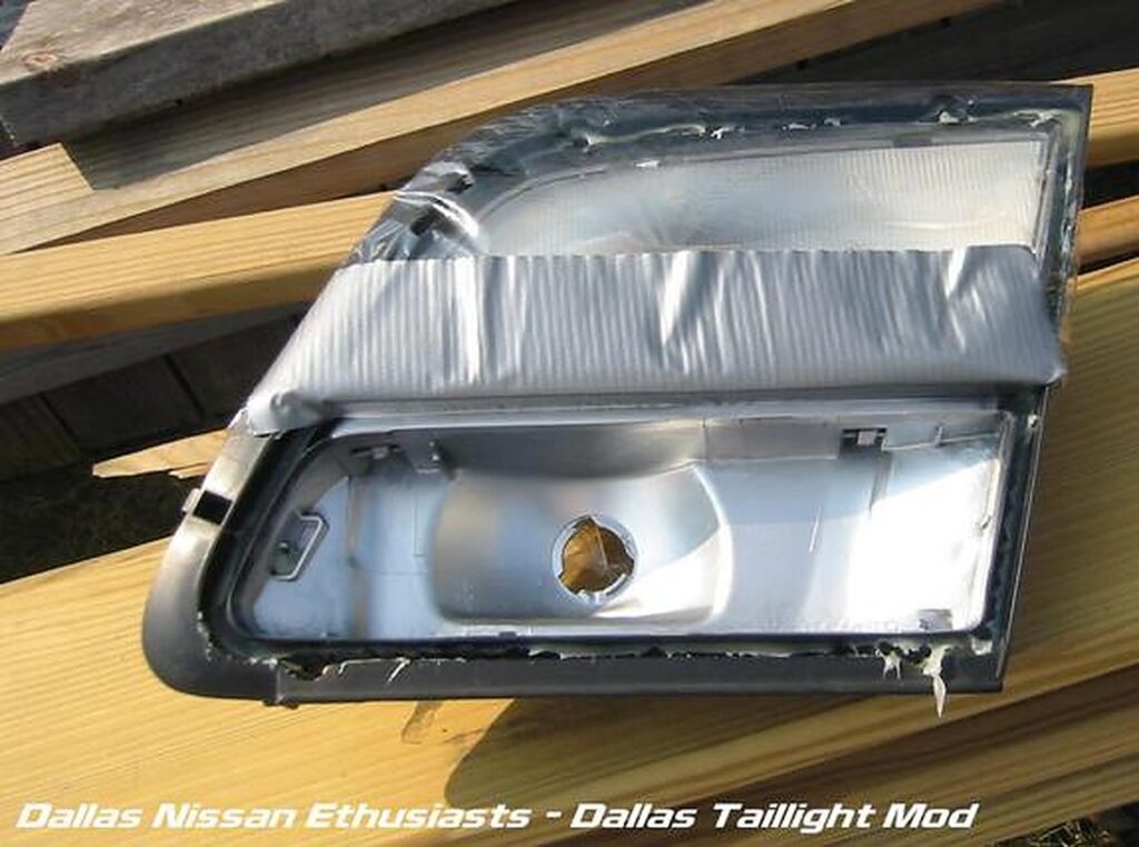
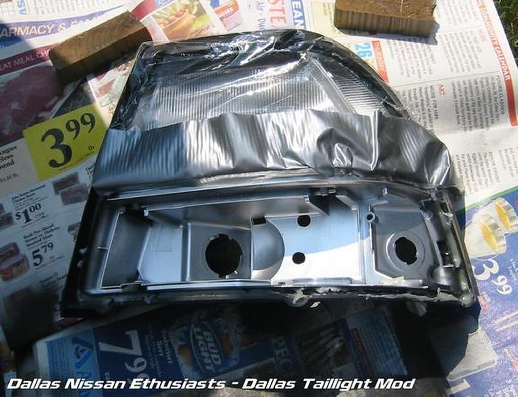
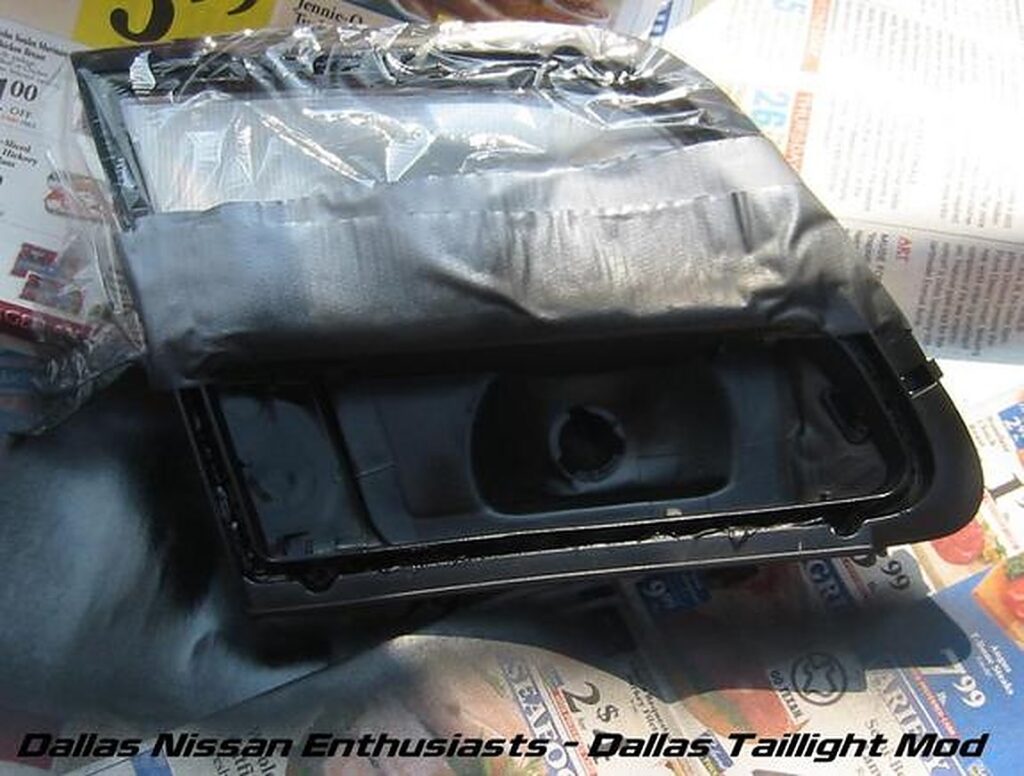
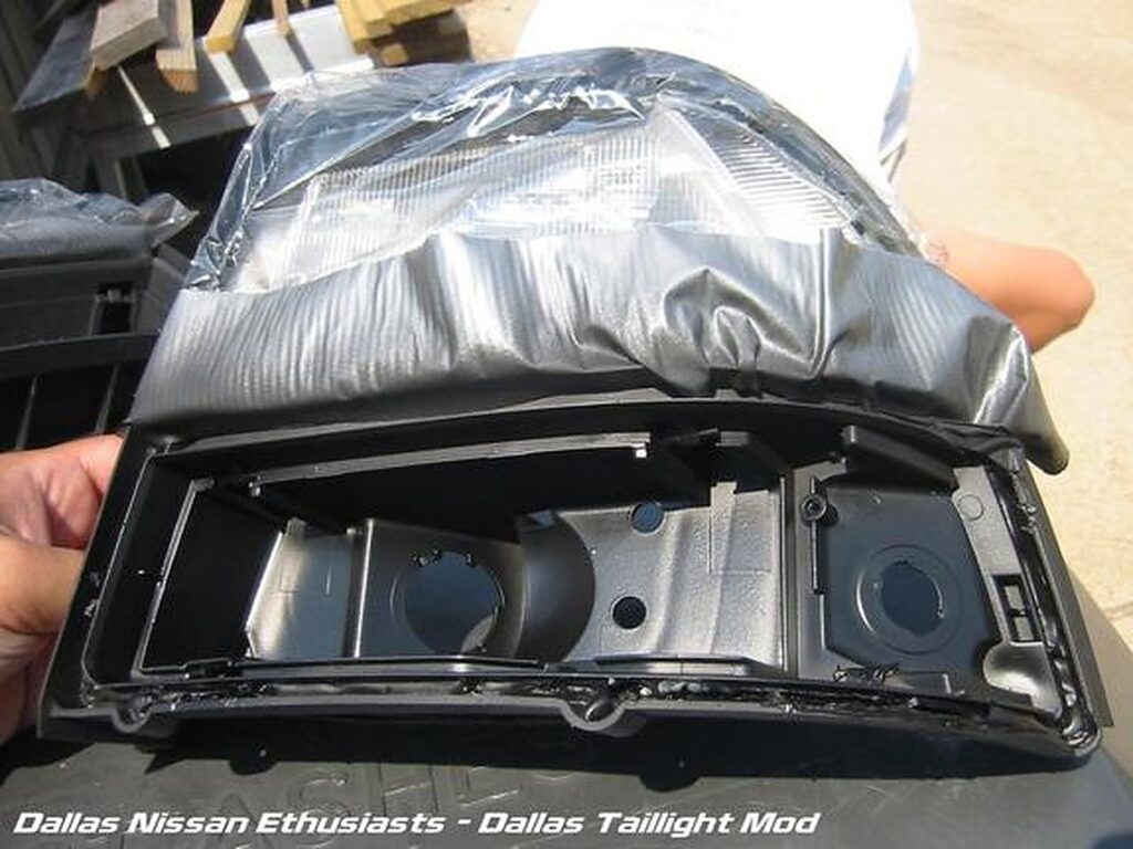
Now that all your lenses have been removed from their housings, prepare the housings to be painted. The best thing would be to use painting tape and some paper to cover the areas you do not want painted, but all we had at the time was duct tape and saran wrap. You can pick up painting tape at your local Home Depot or Lowes.

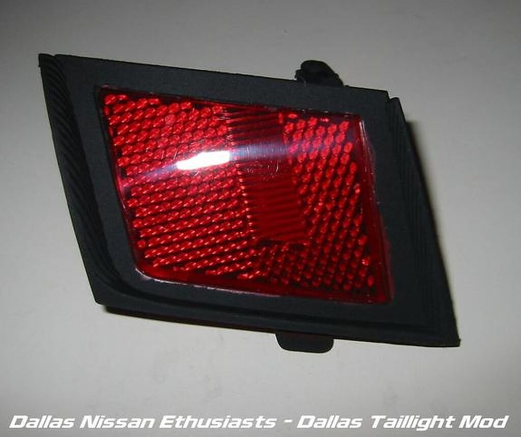
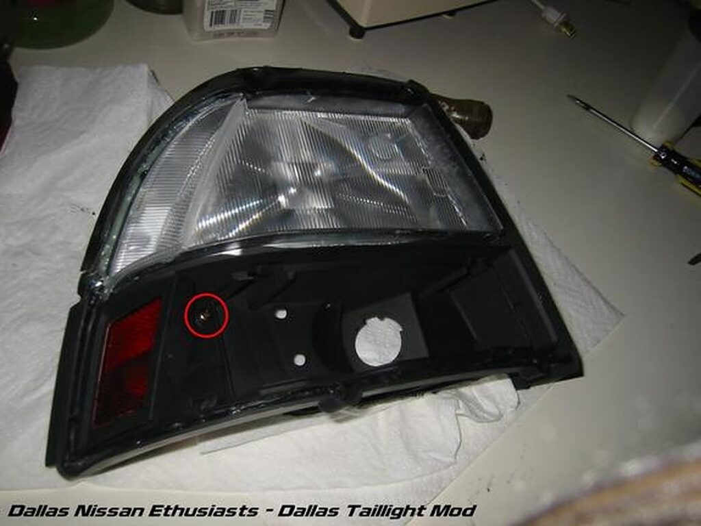
Now, for the turn signal assemblies, you must remove the little red side light cover by removing the one screw that holds it in (sorry no pic). Using the painting tape (or duct tape in our case) cover the reflective part. As to not paint it black. Some people have chosen to leave these covers out completely, but that is your choice.

Once you have the protective stuff all put on the tails, you can spray paint your tails. Be sure to get all the corners and hard to get areas for that clean look. I recommend holding the can 12 to 18 inches away from the housing itself as to not get overspray. We put two coats of paint to make sure we got everything. This is what your tails should look like.

Now take your paint turn signal tail assemblies and your painted reflectors and put them back in. Don’t forget to put the screw back in (red circle).

Once the paint has dried, you can put the lenses back on the housings. Use the heat gun to heat up the glue a bit first. Once they are back together, put them in the oven for about 5 mins at 200 degrees. After 5 mins pull them out. The glue has been reheated so that you can push the lenses onto the housing more for a better seal. Once all together, your tails should look like this.

Now all you have to do is put the tails back in and you’re done! What a nice a$$ you have. 🙂


Loading

Tools:

  • Flathead screwdrivers- small and medium.
  • Large Philips screwdriver.
  • Rachet- 10mm sockets.
  • Voltmeter, Voltage light, or Multimeter.
  • Electrical Tape
  • Approx. 3 feet of wire.
  • Wire Taps

Info:
This modification is a very easy process that allows the fog lights to be on with the parking lights. It also allows the fog lights to remain on with the high beams. This process was done on my 1997 Nissan Maxima SE, automatic.

Let’s Begin:
Click the image to open in full size. Click the image to open in full size.
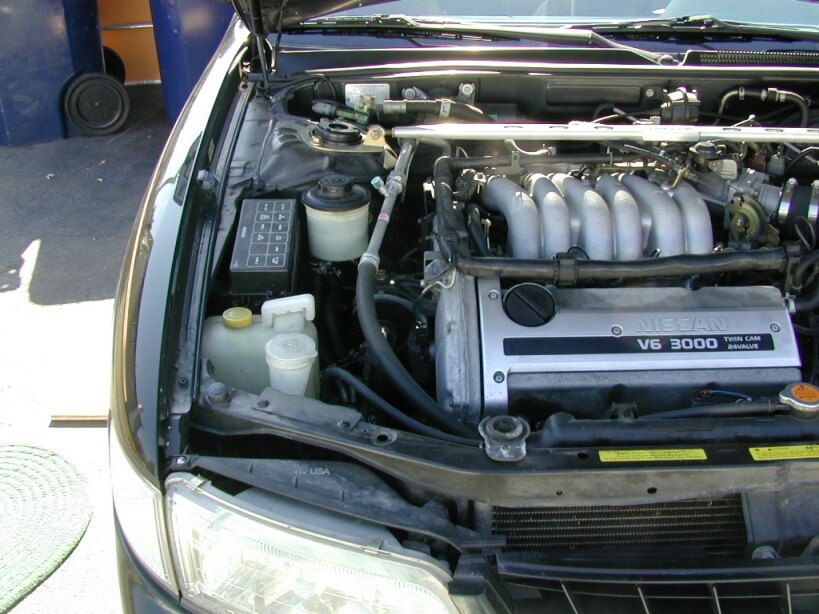
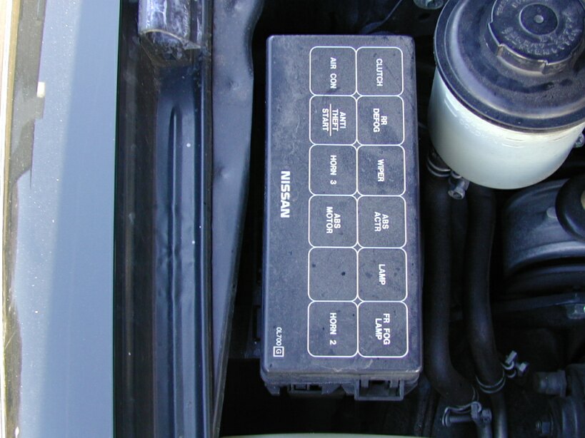
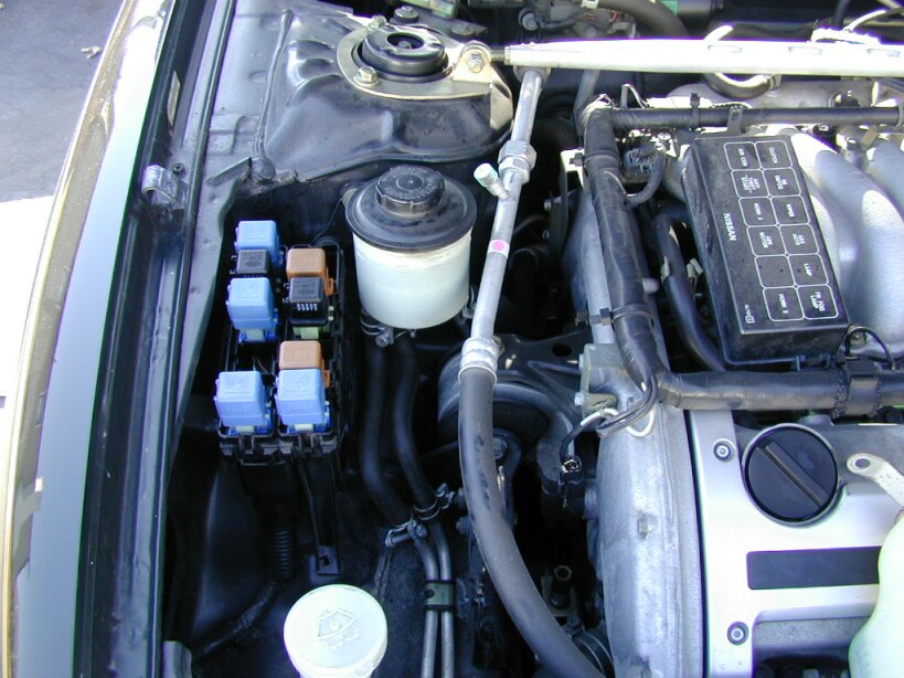
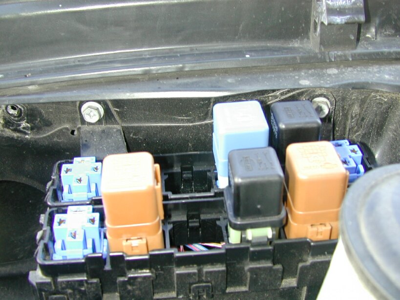
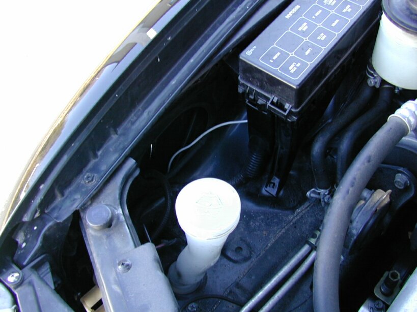
The relay box is located on the passenger side of the engine bay, right next to the coolant reservoir. Close up of the relay box. Notice the Fog Light relay is marked.

Click the image to open in full size. Click the image to open in full size.
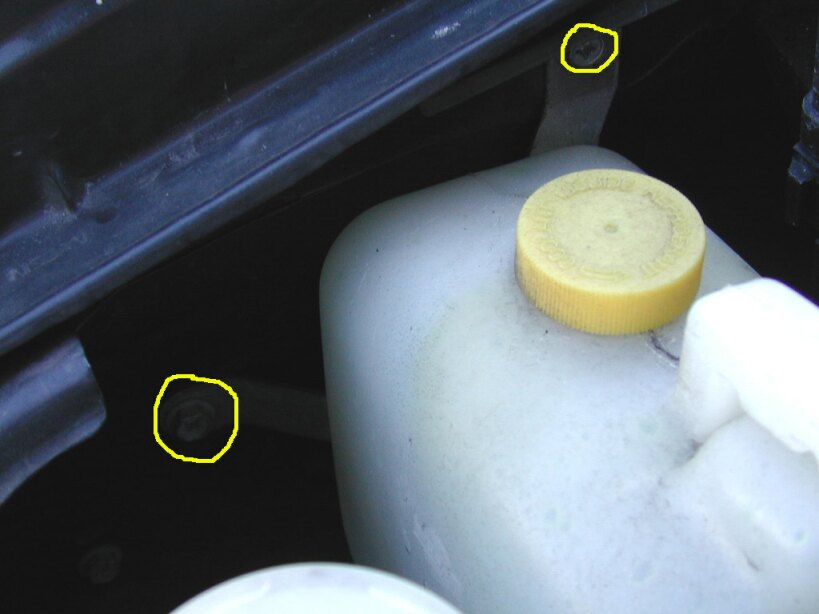
In front of the relay box is the coolant reservoir. Remove the coolant reservoir by removing the two hex head screws. You can use a large Philips head screwdriver or a 10mm socket. Place the reservoir out of the way. I put it in between the engine and the radiator, it’s sits there without disconnection the hose. Remove the top of the relay box. This is easy, there are only a few clips to undo. Put the top on the side. > Click the image to open in full size. Click the image to open in full size.
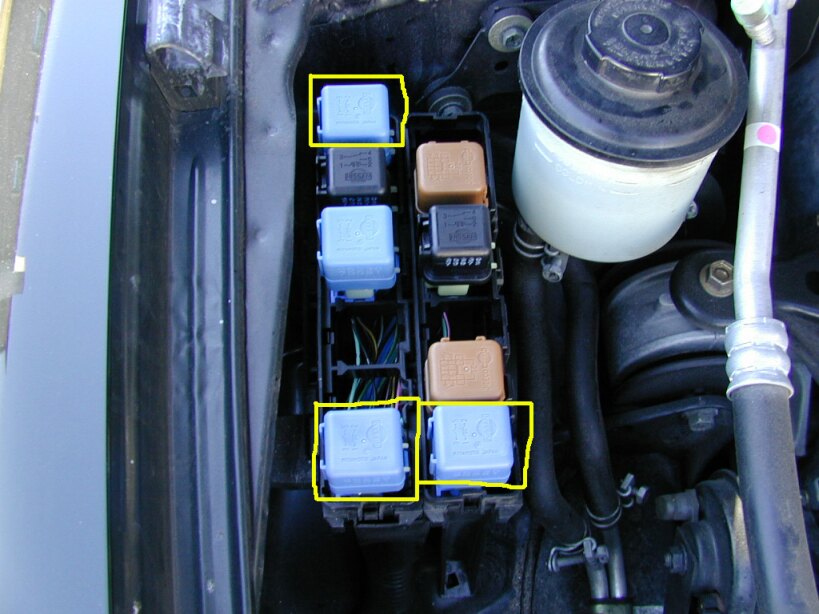
Now you can see the relays.
The three relays highlighted in yellow need to be remove in order to remove the relay box. I believe if you have a manual transmission that there is a forth relay that needs to be removed (it would be in the upper right of the relay box)
**These relays should all be the same, but just in case make sure you remember where they originally were.**
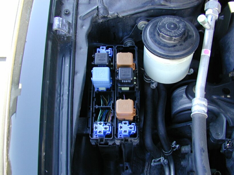
This is what the box looks like with the relays removed.
Click the image to open in full size. Click the image to open in full size.
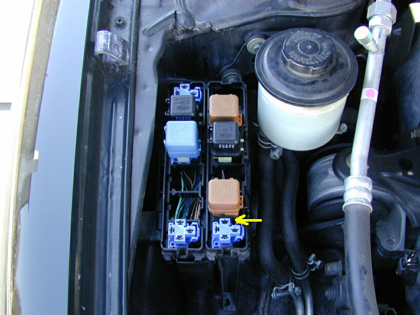
Turn the lights on and test the relay with the voltmeter (or other electrical device). The marked terminal should give around a +12V reading. You can use the terminal across from it as the ground. The two hex head screws need to be removed. You can use a large Philips head screwdriver or a 10mm socket.
Click the image to open in full size. Click the image to open in full size.
^^FENDER WALL SIDE^^ ^^ENGINE SIDE^^

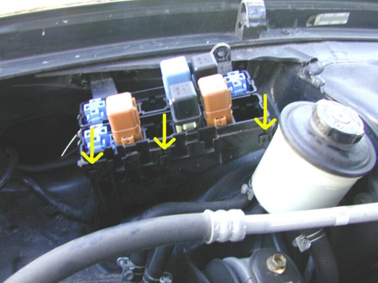
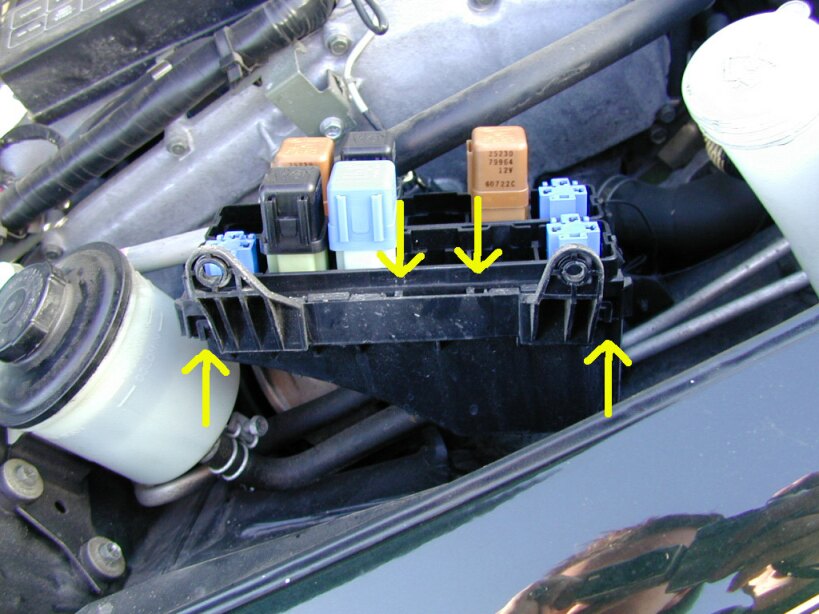
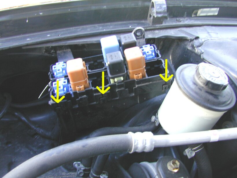
Once the relay box is remove from the frame, it need to be taken apart. There is an upper and lower piece. In order to take it apart there are three clips on the side that faces the engine and two of the same clips on the fender wall side. But on the fender wall side there are also two additional clips. I used a small screwdriver to unlatch all the clips, be careful not to break anything. All the clips are marked in the two pictures above.

Click the image to open in full size. Click the image to open in full size.
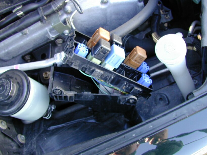
Here is a picture of the two pieces of the relay box apart. With the relay box open, you want to locate the +12V terminal of the Fog light relay. It’s the green/yellow wire. I’ve marked it with an arrow and outlined it in yellow. You want to cut this wire, make sure to leave yourself enough wire on the relay side of the wire to splice into. Once the wire is cut, tape off the +12V wire with electrical tape (this is the half of the wire that isn’t attached to the relay)
Click the image to open in full size. Click the image to open in full size. Click the image to open in full size.
^^WIRE TAP^^ (Radio Shack). Splice into the green/yellow wire with a long wire, around three feet. I used a wire tap to do this, but it can be done in other ways. Make sure to wrap it with enough electrical tape. The new long wire needs to be run out of the relay box. So I cut a small hole in the bottom to run the wire out of. You can also see in the picture the original +12V wire that is cut and wrapped in black electrical tape.
Click the image to open in full size.
Put the relay box back together.
Reattach the box to the car with the two hex head screws.
**To test the lights: Turn on the parking lights, then touch the new wire to the positive terminal (RED) of the battery. The fog lights should turn on when the wire touches the battery. They should also remain on with the high beams.***
Click the image to open in full size. Click the image to open in full size. Click the image to open in full size.
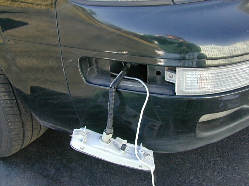
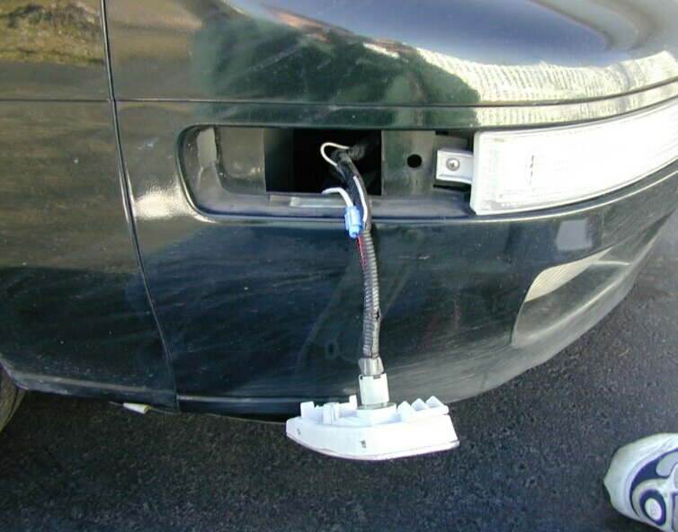
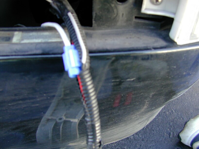
Remove the corner light with a screwdriver (wrap with a cloth to protect the lenses), it should pop right out. Run the wire through the fender wall to the corner light. Splice the new relay wire into the red/blue wire. Again, I used a wire tap and then wrapped the entire thing with lots of electrical tape. Push the lenses back into the bumper.
YOUR DONE!!!
Turn the parking lights on and make sure the fog light switch is on too. Now your fogs will also be on. Turn on your headlights with your high beams on, your fog lights will remain on.

Loading

Owner: Meximax

Year: 1996
Model: Maxima
Color:  White
Transmission: 6-Speed Manual
Trim: GXE

Highlights: Fully built FWD VQ35 with a overspinning, belt-slipping Vortech V2 SQ running on custom JWT tune and mated to a 6-speed HLSD putting down 443whp/378wtq (STD corrected) on 93 octane. Uncorrected numbers were 454whp and 387wtq.

Mod List:

Engine:
– Swapped VQ35 with VQ30 timing equipment (no variable valve timing)
– 8.8:1 Wiseco Pistons (stock bore)
– Eagle Rods w/ 3/8” ARP Bolts
– Balanced/Blue Printed Rotating Assembly
– ARP Main and Head Studs (std)
– JDM Cams (AKA JWT S1 Knockoffs) on custom intake cam timing
– Cosworth Headgasket
– JWT Valve Springs/shims
– Mild head work (gasket matched intake/exhaust ports)
– New OEM VQ30 timing equipment (chains, tensioners, etc., including water pump)
– Custom Z33 Intake Manifold w/ Motordyne 7/16” Spacer
– 70mm ’01Pathfinder TB

Boost:
– Vortech V2 SQ
– Matty’s V1 SC Plate
– 2.62” pulley
– FMIC (bar and plate) 29*12*3.5, 3” in/out
– 3” charge pimping

Transmission:
– Swapped ’03 6-spd transmission
– Helical Limited Slip Differential from Spec V
– 3.813 Final Gear retained
– Stock Flywheel with welded A32 CPS Signal Disk
– JWT Z33 Clutch
– Stock ’03 6-spd axles
– Redline 100% heavy duty shockproof oil

Engine Management System (EMS):
– JWT Custom Boost Tune (93 octane and 116 octane, 7300 rev limit)
– Apexi SAFC
– J&S Safegaurd w/ knock monitor
– Kenne Bell Boost-a-Spark
– NGK Iridium gapped to .035
– Innovate XD16 O2 Wideband

Fuel:
– RC 550 Injectors
– Walbro 255 high pressure fuel pump (hardwired)
– Custom Dual Feed Returneless rails on OEM return system
– Aeromotive Adjustable Fuel Pressure Regulator (1:1 rise rate)

Exhaust:
– Hotshot headers w/ custom 3” collector
– Custom 2.5” True dual with X-pipe

Loading

Owner: emdot

Year: 1996
Model: Maxima
Color: White
Transmission: Manual 5-Speed Transmission
Trim: SE

Mod List:

Engine and Transmission

  • 2003 VQ35DE 3.0 Timing Components and Cam Adapters
  • Vortech V2 Supercharger
  • 3.33″ Pulley (~9 PSI)
  • Blitz BOV
    NWP VIAS Delete Plate
  • RC 440cc Injectors
  • Aeromotive A1000 Fuel Pressure Regulator
  • WeaponR Fuel Rail Adapters
  • Steel Braided Fuel Lines
  • Walbro 255LPH High-Pressure Fuel Pump
  • Z32 MAF
  • Apexi SAFC-II
  • AEM Water/Methanol Injection
  • Cattman Y-Pipe to 3″ Full Exhaust
  • ACT Heavy Duty Pressure Plate
  • ACT 6 Puck Unsprung race disc
  • 1-Piece SS Clutch Line

Exterior and Suspension

  • Custom White Pearl Paint job
  • 97-99 Front End Swap
  • Stillen Full Lip Kit
  • Carbon Fiber Hood
  • Paradox Full-size Roof Spoiler
  • Work Equip 17×8 +22 F 17×9 +20 R
  • KSport Kontrol Damper System
  • AddCo Rear Sway Bar
  • Stillen Rear Upper Tie Bar
  • Goodridge SS Brake Lines

Interior

  • Carbon Fiber Dash Trim
  • LED Gauge Cluster, Door switches, Dome light, Map light, OEM Security Light
  • ProSport Electronic Boost Gauge in Single Pod
  • AEM Methanol Progressive Controller
  • Recaro Neck Pillows
  • Alpine CD9853 Head Unit
  • Stock Bose Speakers
  • Rockford Fosgate Amp
  • Rockford 12″ Sub

Loading

Community Member Credit: ATTappman

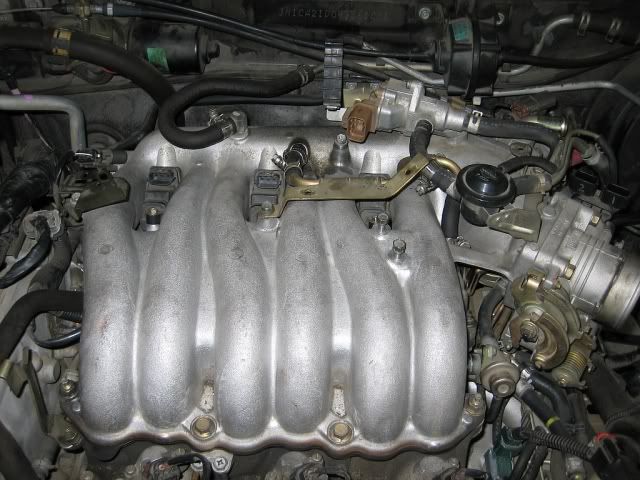
Recently I had to remove my UIM to tighten the hose clamps on the coolant hoses connected to the backside of the UIM. Here’s a description of the job with some photos. The car is a 1997 GLE Fed spec.

Part 1:

First, you have to remove the air intake. Start by popping off the four clips that secure the top of the air filter box:

Disconnect the MAF sensor electrical connector:

Disconnect the two large vacuum hoses and one small hose from the resonator:

Note that I unhooked the IACV end of the second large hose, to keep the hose attached to the resonator.

Part 2:

Loosen the hose clamp on the throttle body, wiggle the air duct off of the throttle body, and lift the whole air intake assembly out of the engine bay:

Disconnect the two electrical connectors from the throttle position sensor:

Disconnect the four electrical connectors from the IACV/fast idle solenoids/EGR temp sensor:

Part 3:

Unhook the cruise control and accelerator cables from the throttle lever. Note that the accelerator cable runs underneath the little tab on top of the throttle lever:

Remove the three 10mm bolts that secure the cable brackets to the UIM. Move the whole assembly to the back of the engine bay:

Disconnect the electrical connector on the EVAP purge volume control valve:

Part 4:

Disconnect the electrical connectors to the ignition coils and the front O2 sensor:

Unhook the wiring harness. It’s secured by plastic clips. With a pair of needle-nose pliers, compress the two “wings” on the bottom of the clip while simultaneously lifting up from the top. Move the wiring harness to the passenger side of the engine bay:

Remove the two 10mm and two 12mm bolts/nuts securing the EVAP purge control valve and the EVAP purge volume control valve to the UIM:

Part 5:

Remove the 10mm bolt holding the EGR temperature sensor bracket onto the IACV. This bolt is hard to see – you can locate it by feel. You’ll need a 3″ extension or a deep socket. The EGR temp sensor wire is in the way – make sure to move it aside to keep from pinching it with the socket. (No pics for this – it’s too hard to see).

Remove the three 12mm bolts holding the IACV to the throttle body. You need an extension for the bottom bolt (my camera battery went dead here and I switched to my cell phone camera – the pics are blurry, sorry):

Lift off the IACV, being careful not to lose the gasket in the engine bay:

Move the EVAP valves back toward the driver’s side of the engine bay. Most of the hoses will still be attached:

Part 6:

Remove the clamps on both ends of the PCV hose assembly, remove the 10mm bolts holding it to the UIM, and remove it:

Unscrew the two screws holding each ignition coil, and pull out the ignition coils. (No pics).

Unhook the vacuum hose from the UIM to the brake booster:

Now comes the hard part. The UIM is bolted onto the rear cylinder head with two support brackets. The EGR guide tube is also bolted to the UIM with two bolts. All of these are 12mm. The best way to locate the support bracket bolts is to feel with your hand along the firewall side of the UIM. Here’s what it looks like with a socket and ratchet on one of the bracket bolts:

You can see one of the EGR tube bolts, but you have to locate the other one by feel. It’s difficult to get a socket on the right UIM bracket bolt. You need a pretty shallow socket and a low-profile flex head ratchet (this is one job where Snap-on tools pay off). If you can’t use a ratchet, try a 12mm offset wrench. Once you loosen the bolts, use a socket to spin them off. Be careful not to drop them.

Taking off the left EGR tube bolt:

Part 7:

At this point, I was soaked with sweat and had a backache, so I stopped taking pictures.

The only remaining bolts are the four 12mm bolts on the front of the UIM. There’s a pattern for tightening these bolts, so I loosened them in the opposite order. If you’re looking down at the UIM from the front of the engine bay, the tightening order is 4-1-2-3 from left to right, so take them off in the reverse order.

Now the only thing holding the UIM on is two coolant hoses in the very back. If the UIM won’t separate from the lower intake manifold, take a thin putty knife and gently pry between the UIM and the gasket, being careful not to gouge the UIM.

Next, get an assistant (I used my wife – she’s a good scout) to hold the UIM as far up in the air as they can. This will reveal the two coolant hoses on the back of the UIM. It’s an extreme PITA to loosen the hose clamps and pull off these hoses. When you pull on them, you just pull the UIM and your assistant toward you. It took me a lot of patience and a lot of swearing to get them off. Getting them back on is no fun either. Maybe somebody can share a trick for this.

With the coolant hoses off, you can lift the UIM out of the engine bay. Here’s what it looks like with the UIM removed:

You can see the two support brackets and the top of the EGR guide tube. Here’s what my EGR guide tube looked like the first time I took the UIM off:

Reinstallation, as they say, is simply the reverse of removal.

Be careful not to knock the EGR tube gasket off into the engine bay. If you put in a new EGR tube gasket before reinstalling the UIM, it helps to tie two loops of fine dental floss through the EGR tube bolt holes and the gasket. This will secure the gasket to the EGR tube and keep it from falling off when you’re putting the UIM back on.

When reinstalling the UIM bracket bolts, get your assistant to move the UIM up and down slightly so that you can align the bolt holes on the UIM with the bolt holes on the cylinder head.

As you may have noticed, I rethreaded most of the bolts into their holes to keep from losing them. The ones you can’t do this with are the IACV/EGR temp sensor bracket bolts, the UIM support bracket bolts, EGR tube bolts, and UIM bolts themselves. I made post-its for each set and put the bolts on the post-its.

I used Permatex gasket adhesive to hold the UIM gasket and the IACV gasket in place during reinstallation. It was mildly successful.

That’s about it. Hope this helps somebody.

Loading