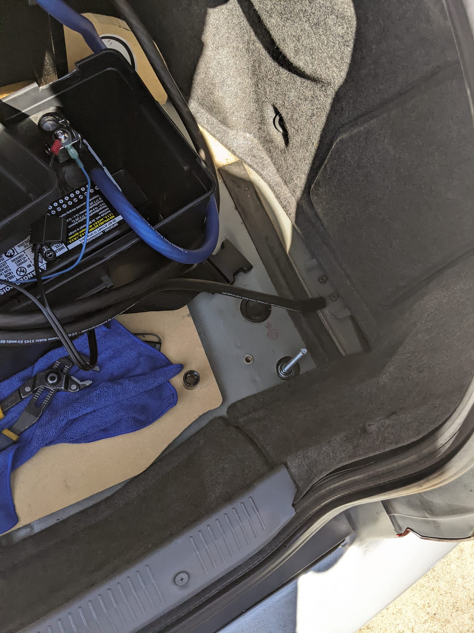
Finally decided to replace my main ground for the battery relocation. It was originally under the mount bracket for the scissor jack in that little pocket, but with mega shitty crimp terminals and basically to body sheet metal.
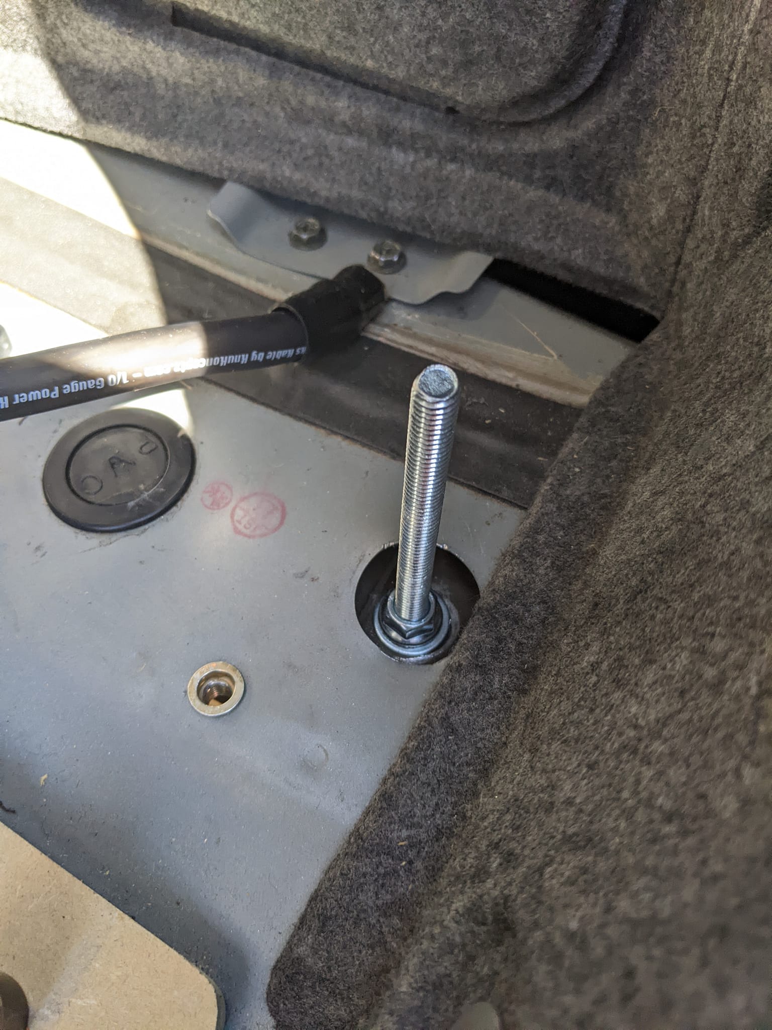
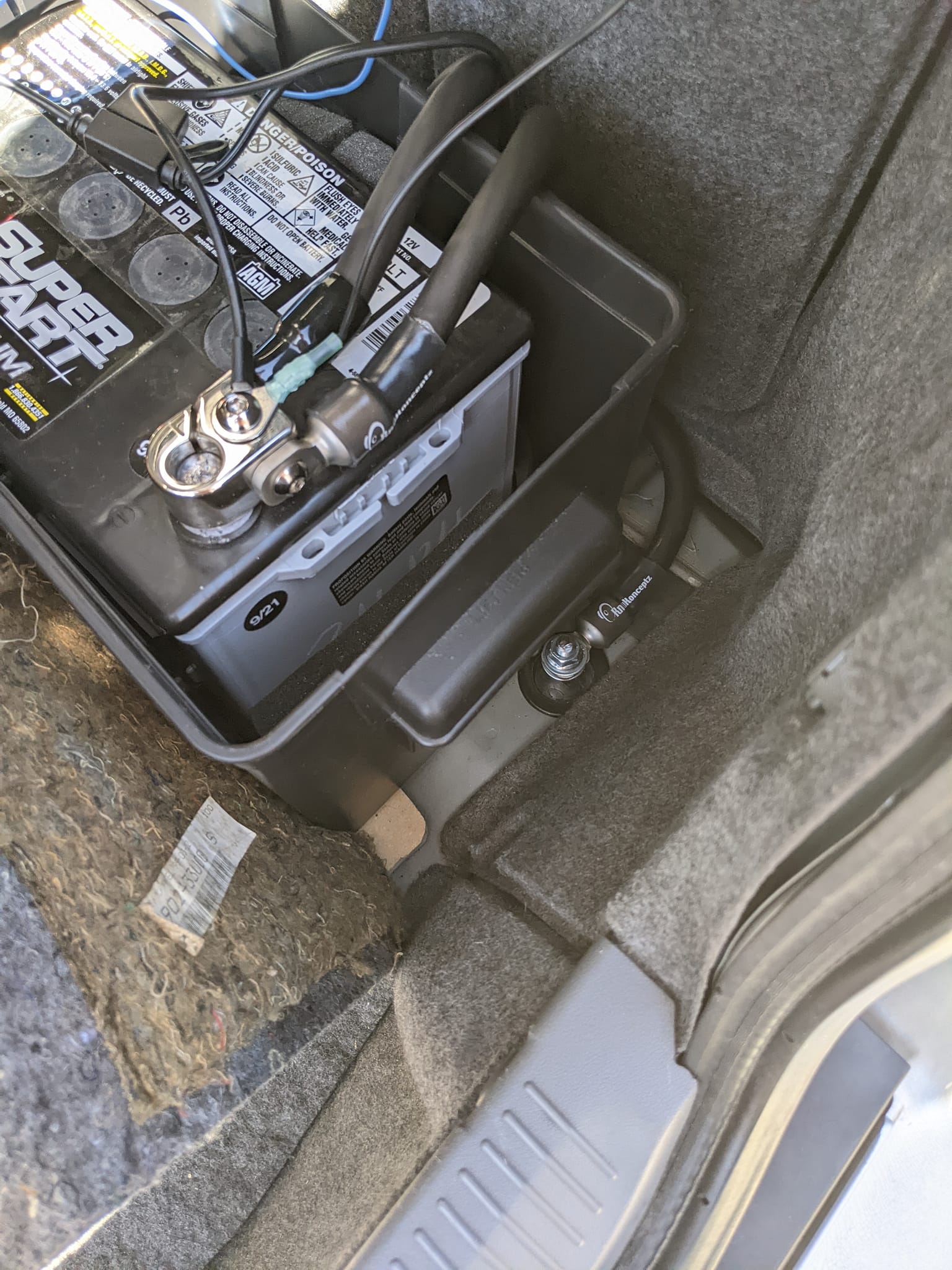
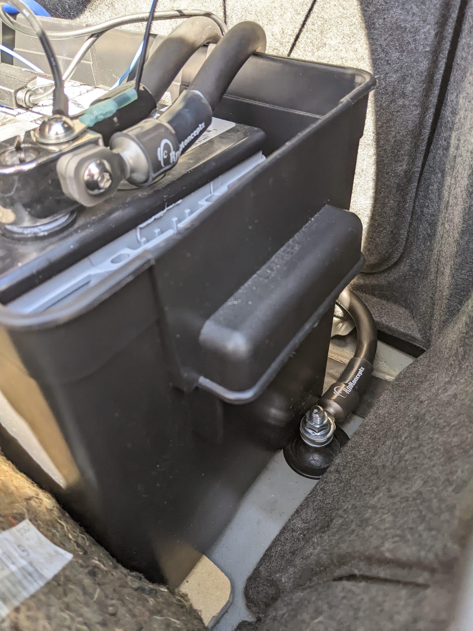
Started by popping off that little cap to reveal the bolt to the bumper support. Removed the bolt to find the tacked in nut no longer attached and the threads on nut and bolt are both just mangled to hell… Went to Lowes and ended up with a 6 inch 3/8-16 threaded rod and various nuts and washers. Have a nylock nut underneath, then a flanged lock nut to sandwich that. Drilled a hole in the cap to seal it back up, then ran down another nylock nut and sandwiched the new KnuKoncepts terminal. Cut off about 2″ of excess threads and she’s good to go! (Need to get one of those battery terminal covers).
I’ll slowly but surely redo the others and add grounds in the front!
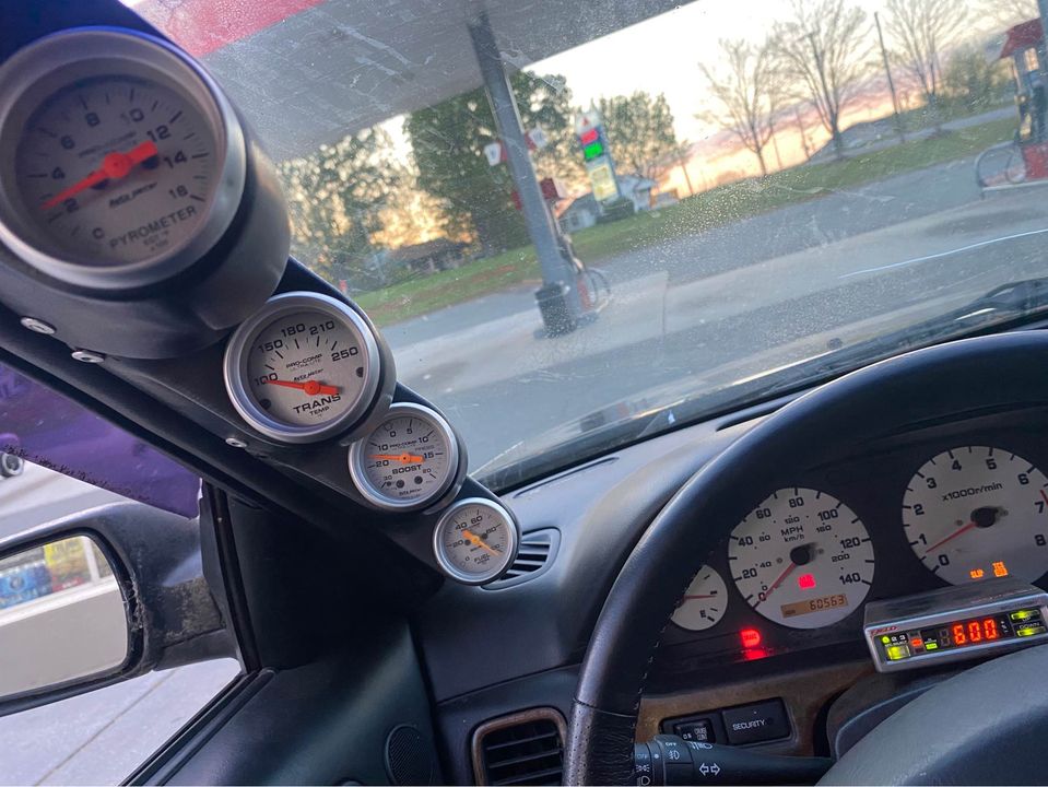
The front side of your G-TECH/Pro EGS has the main RPM gauge window with the backlit numbers. Colors in the backlight are adjustable to your car’s interior. During the time EGS is turned off the display will appear very dark, that’s normal. As soon as the unit is powered the dial face and the RPM needle will become visible. The aluminum back of the EGS may get warm during the operation, not to worry, that means aluminum is doing its job and dissipating heat generated by the powerful backlight LEDs
In this post I will go over the process I went through when building my turbo kit. As many know, the car was first equipped with a rear mount turbo for many years.
Some information about the car:
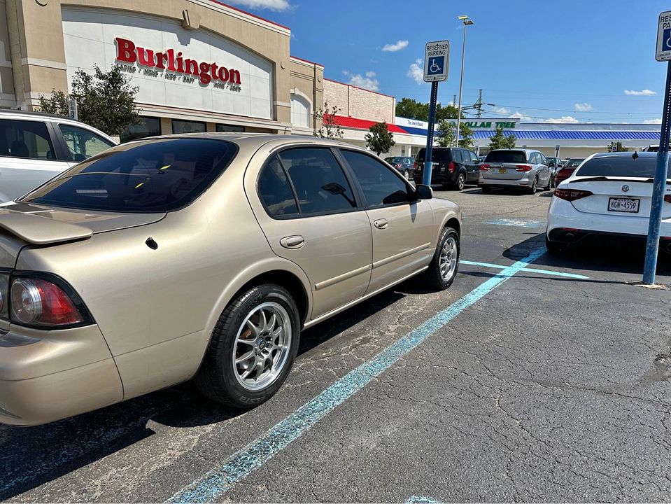
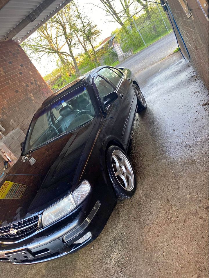
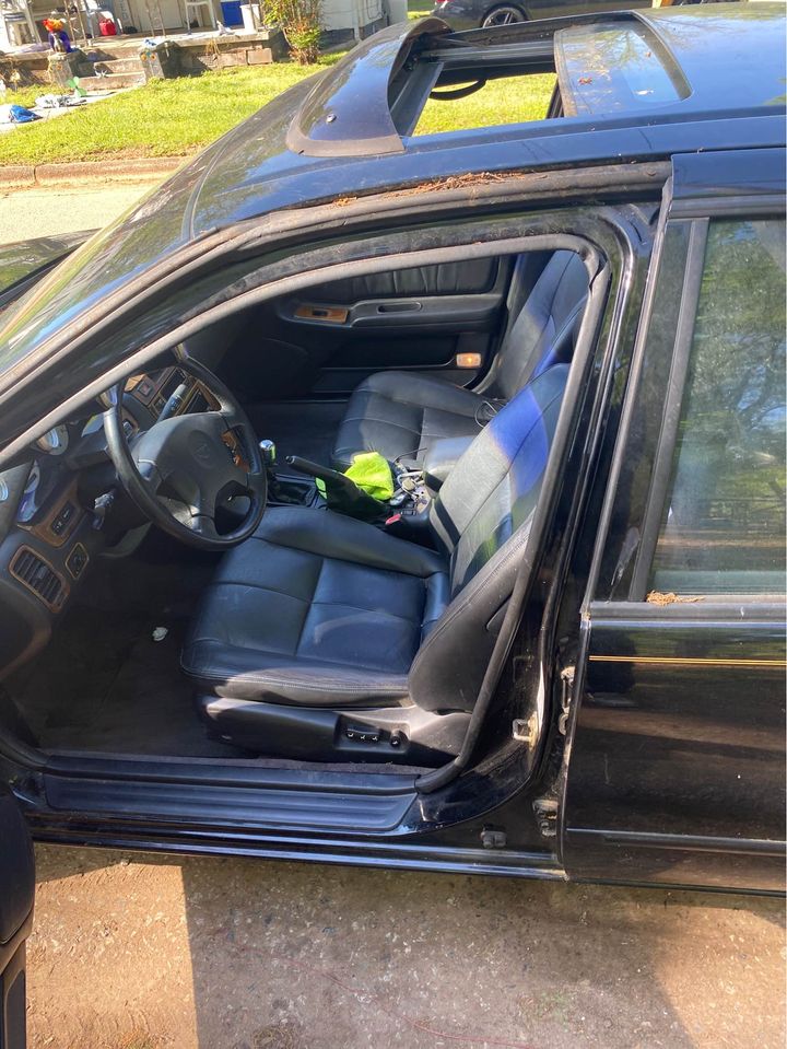
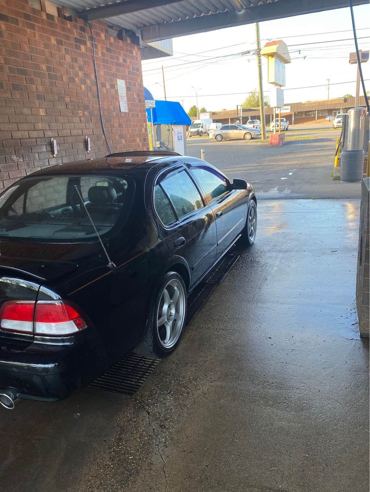
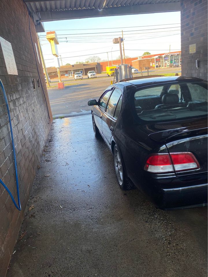
1997 Maxima
Automatic
Turbo (initially rear mount turbo)
Rear Mount Turbo Preview
As a rear mount turbo, it was a great experience. It was my first time being in a turbo car much less driving one. I saw an episode of Powerblock on SpikeTV showing an installation of a rear mount twin turbo setup on a Corvette. Right away I started brainstorming and realized how easy it would be to do it. I started gathering parts and in a weekend we installed it. I went for my first drive, felt what it was like to get anything greater than 0psi and boy was I hooked. I will make a post soon about the details involved with the rear mount turbo.
I used 370CC injectors to begin with.
The turbo was a T04b with a .60ar T4 turbine.
None Intercooled with Meth.
7-10psi
Rear Mount Turbo Dyno VQ30-00VI
(Expect a post about the rear mount soon)
It made 299whp / 291wtq
Front Mount Turbo Design
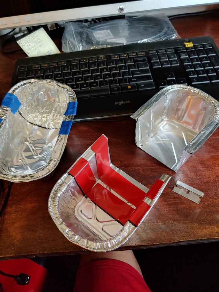
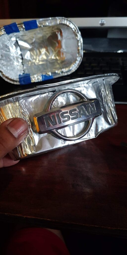
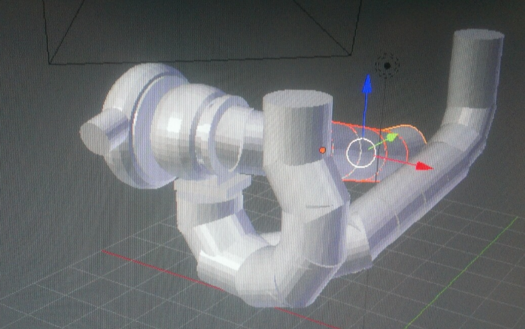
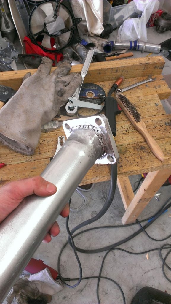
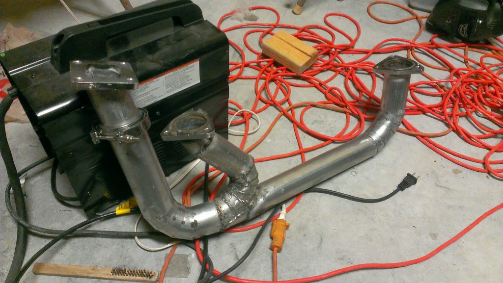
Fast forward several years and the car now garaged I was able to start gathering more tools and I was gifted a Harbor Freight 90amp Flux Core welder. Right away I started piecing together a front mount turbo kit in my mind. I started doing mock up 3D designs to get an idea and better visualize what I was going to do. I did not want to do the usual reverse y-pipe, or have to remove the battery, I wanted it to be efficient, and my own solution. This is the design I started with:
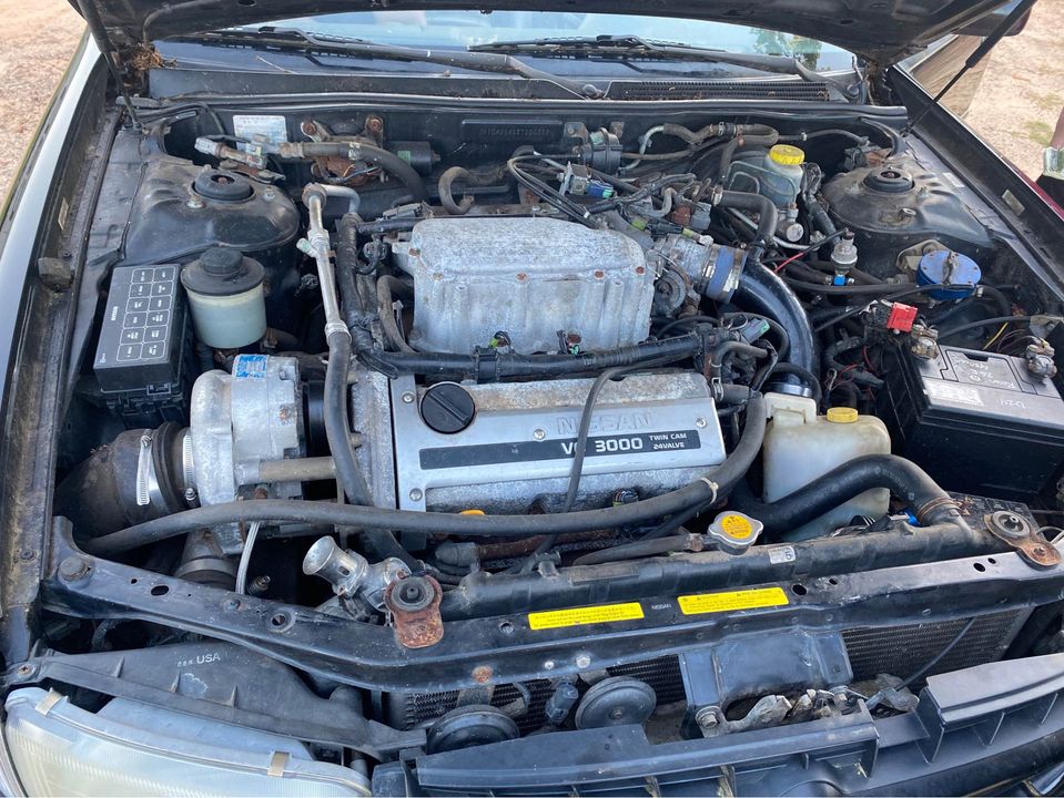
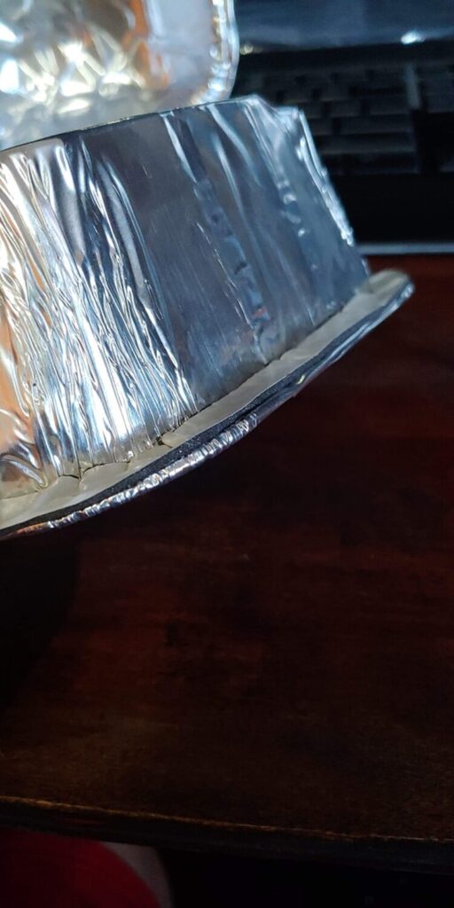
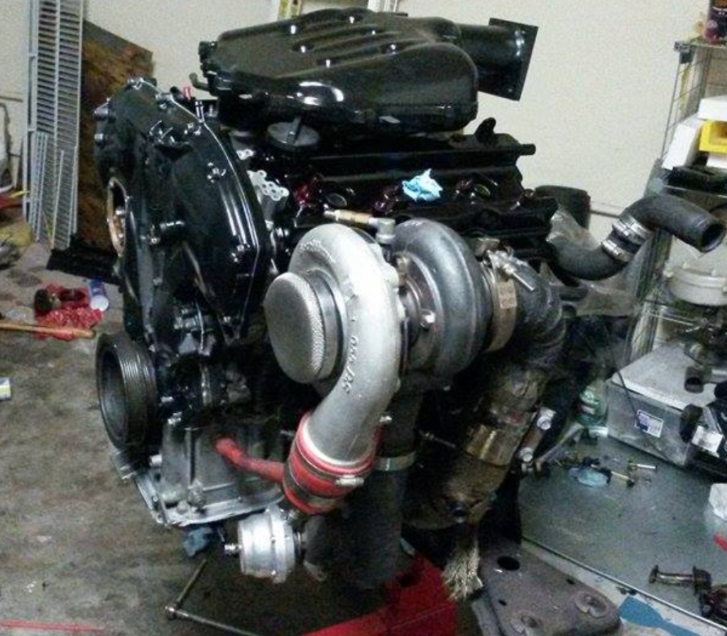
My plan was to place the turbo in the location of the AC compressor and remove the compressor. I mocked up the physical turbo to check the spacing in that area and I decided to put the turbo higher near the grill. Part of the reason for the new position was because I did not want to keep using a scavenge pump; the turbo would require one due to its low position.
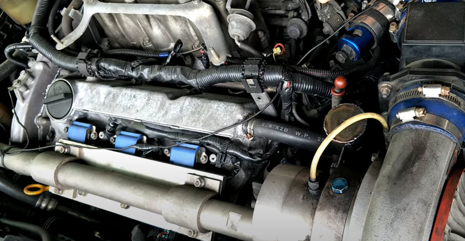
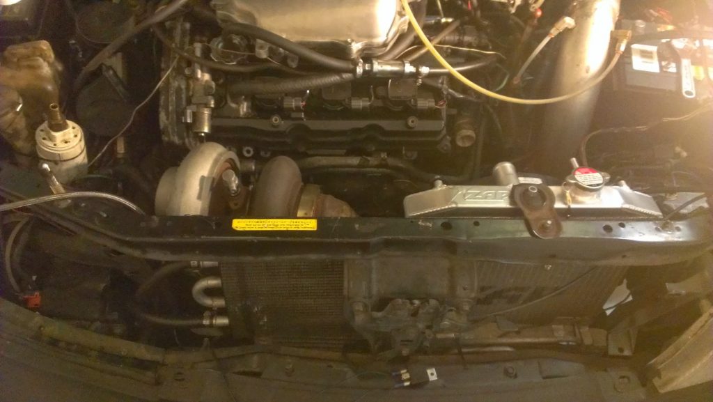
The headers were the factory iron ones, the flanges connecting to the header were reused from the Y Pipe previously used. The feed pipe has the same positioning as the Y Pipe except it aimed forward instead of the back, passing between the crossmember and the oil pan then up towards the alternator and above it. This new location required the use of a half size radiator. I used a Honda Del Sol 2 core with a custom shroud(It will be another blog entry). For the down pipe, you can see in the following pictures that I created a bend from the turbo down to the crossmember. The pipe then turns towards the back of the car and goes in parallel with the feed pipe (y pipe). After the feed pipe the downpipe continues on to the cat back like the exhaust system normally would. Here is the final location:
This video shows the initial engine start up after finishing the turbo kit. This was with the same turbo that was in the rear mount setup, which was an HX40Pro with a Bullseye .70AR turbine housing. This turbo’s spool up was quick as a rear mount and as a front mount with little travel it was instant.
Some of the details of this build:
Turbo: HX40Pro with a Bullseye .70AR
Wastegate: Tial 38mm, open to atmosphere
Blowoff Valve: Tial 50mm
Injectors: ID 1000cc
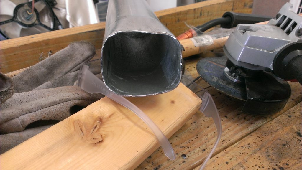
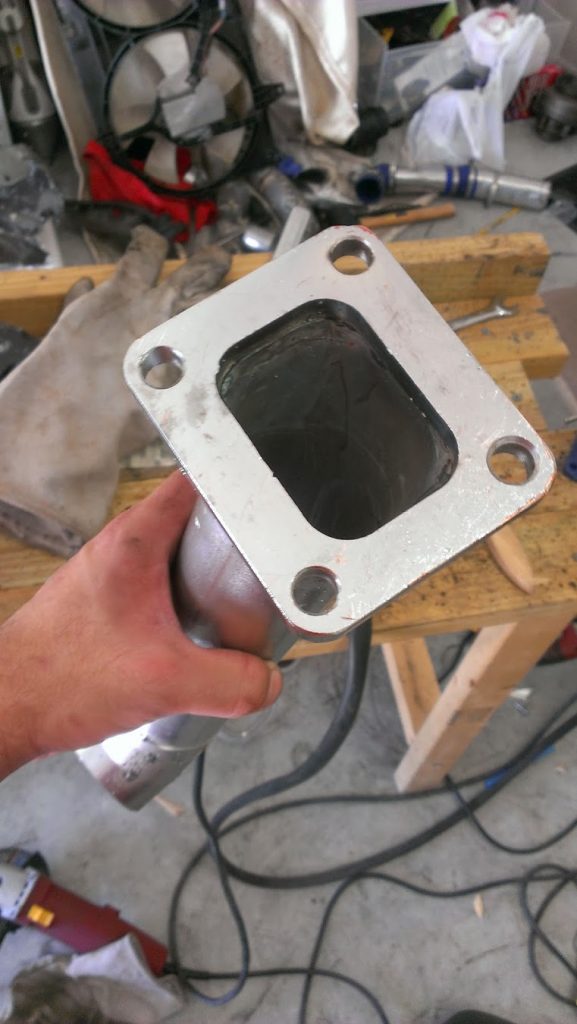
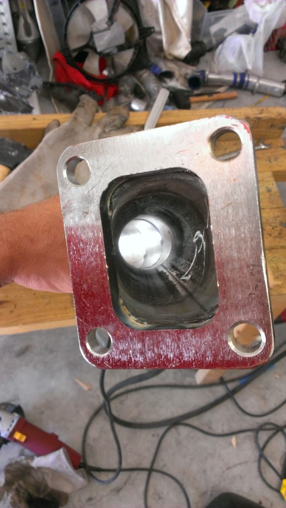
Turbo feed pipe size has 2.25in legs coming off the headers and merging into 2.5inch up to the turbo. There is a v-band in place before the turbine to be able to swivel the turbo around.
I cannot compare between Rear Mount and Front Mount because they had different turbos, I only drove the car briefly with the HX40 before I upgraded it so I do not have data to compare. But most certainly the response time for the turbo was different; the difference between the turbo being in the very rear of the car vs. being at the front was noticeable.
In the next post ill go over the cooling aspect of the setup and how I used a small radiator.
When doing the HR Swap on your Nissan Maxima, you use the DE knock sensor and DE harness since you are using the original wiring harness and ECU to your car.
DO NOT use the fwd hr knock sensor, it’s NOT set up for the DE ECU. You need to use the KNOCK sensor from your original engine.
The HR knock sensor doesn’t get ground from the motor, you need to add a ground to the other pin of the connector.
You can also use a 470K ohm resistor to bypass the knock sensor
Over the past couple of months, I have received several requests to post information on the sub-frame spacer modification. It has taken a couple of months to try several different products and approaches to finally settle on a method that I feel comfortable sharing.
All total I must have spent $400 on an assortment of poly bushings, washers, ceramic magnets, and spacers to finally reach an approach where the modification can be repeated in the $90 to $100 per vehicle range. Since I paid $90 for the original set of spacers that I’m replacing with a hopefully better product, I think it will be worth it. I want this modification to last for several years.
This modification uses a combination of parts from the following vehicles:
1998 Maxima GLE – Recently converted to SE suspension. Note initially this modification was made to the stock GLE sub-frame. Later the 98 GLE was converted to use the triangular sub-frame braces from a 97 SE. Pictures of how the bushings look in both the stock GLE and upgraded SE type suspension are provided.
The suspension uses H&R Lowering springs with Koni STR-T orange struts. New Lower Control Arms (LCA) with end links, poly bushings, inner/outer tie rod ends have been installed. The mod was installed on a vehicle with basically a new front suspension. This car already had a very tight suspension before the modification was made. It just tightened it up a bit more.
1999 Maxima SE – This is the 2nd installation where I used this modification.
This vehicle’s suspension was replaced approximately 3 years ago with H&R lowering springs, KYB AGX struts, new Lower Control Arms (LCA) with end links, poly bushings, inner/outer tie rod ends have been installed. This is the 2nd time that subframe spacers have been used on this vehicle. The original mod was installed on a vehicle with basically a new front suspension. The 2nd (enhanced) modification was made after the 1st modification’s parts worked loose and fell out after approximately 2 years of use. Note this car also had a very tight suspension before the modification. This modification just tightened it up a bit more.
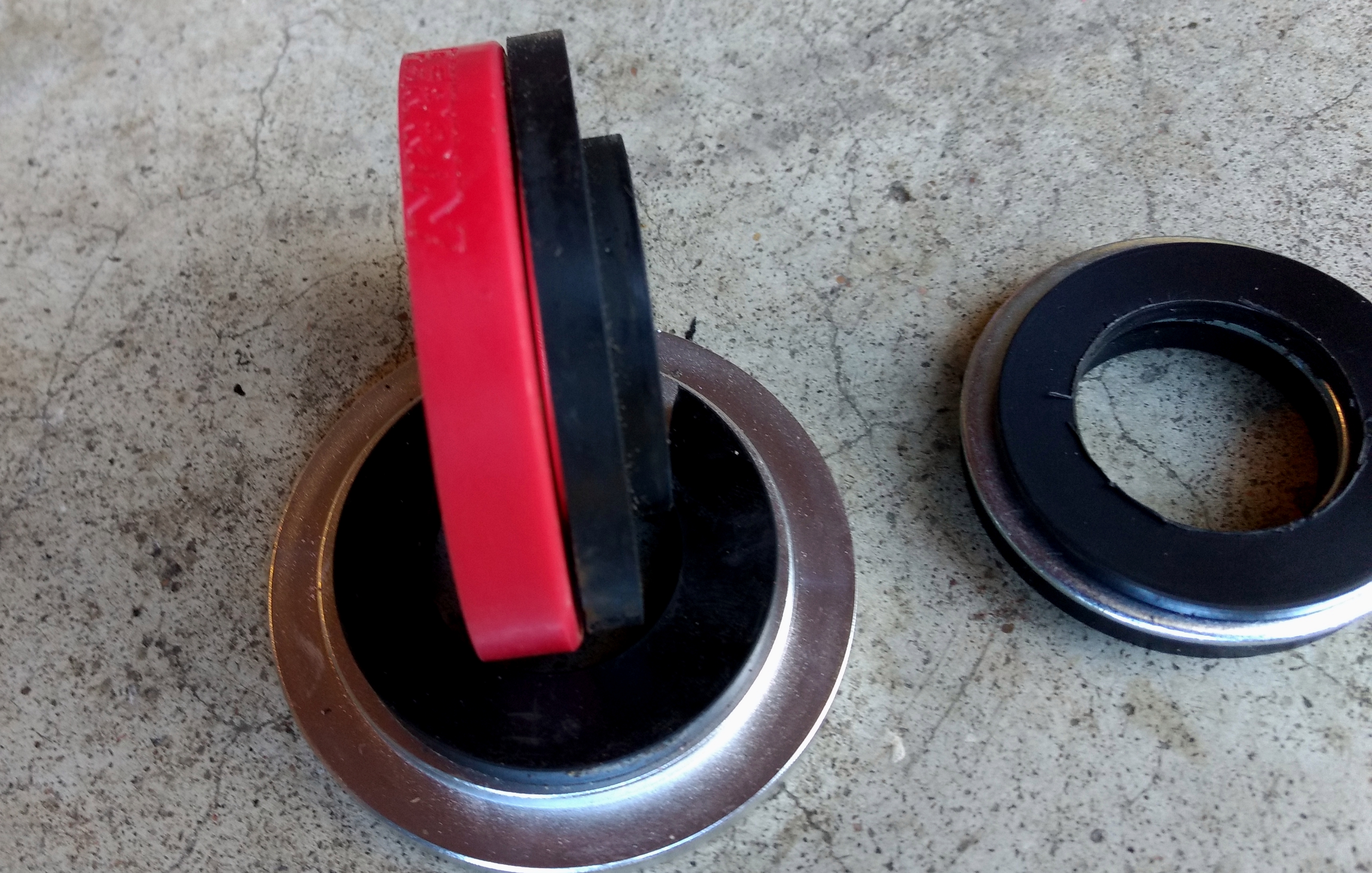
Post Installation Pictures
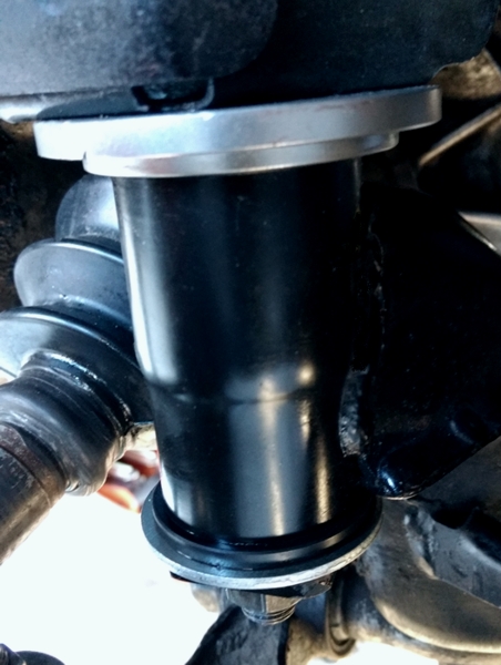
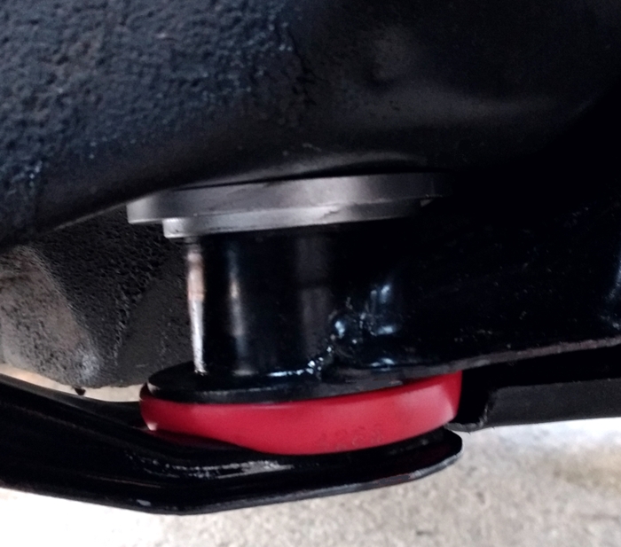
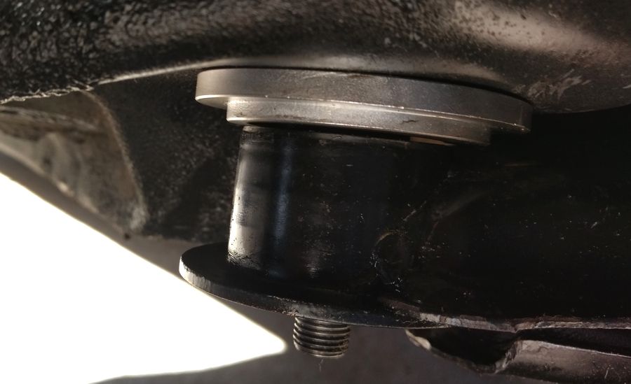
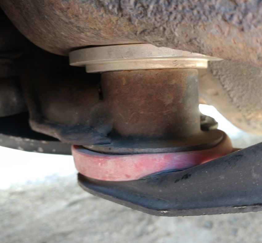
Front 300ZX Aluminum Subframe Spacer with PRG Delrin Titan/Armada spacer and flat washer.
Space between the sub-frame mount post and the body results in a loose sloppy feel when driving over rough places in the road and lowers the amount of feedback from the rack to the driver.
Also, when the sub-frame upper post rubs against the body it can make a creaking noise.
Roughly 3 years ago, I purchased a set of plastic spacers to tighten subframe movement. Unfortunately, the upper spacers were not thick enough to completely stop the movement. Since the upper spacers are C-shaped, the upper rears spacers eventually worked loose and fell out on the street somewhere.
The old spacers helped after the initial installation. Since I could see the gap that remained between sub-frame post and the body would eventually allow the upper C-shaped collar to fall out. So I had to use Gorilla Tape as a temporary measure to wrap the area until I could come up with a tighter solution.
Looking back, I could have stacked up additional washers on the bottom post to remove slack. By then, I had already lost one of the rear spacers. Unfortunately, I just did not have a solution at the time when I realized the old spacers were too loose. Since the spacers are no longer available and the seller was not responding to email when I attempted to buy another set, I decided to find a repeatable solution using a combination common parts from other platforms.
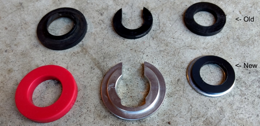
Old to New Parts Comparison
The old parts are in the upper row.
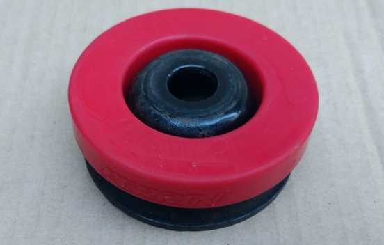
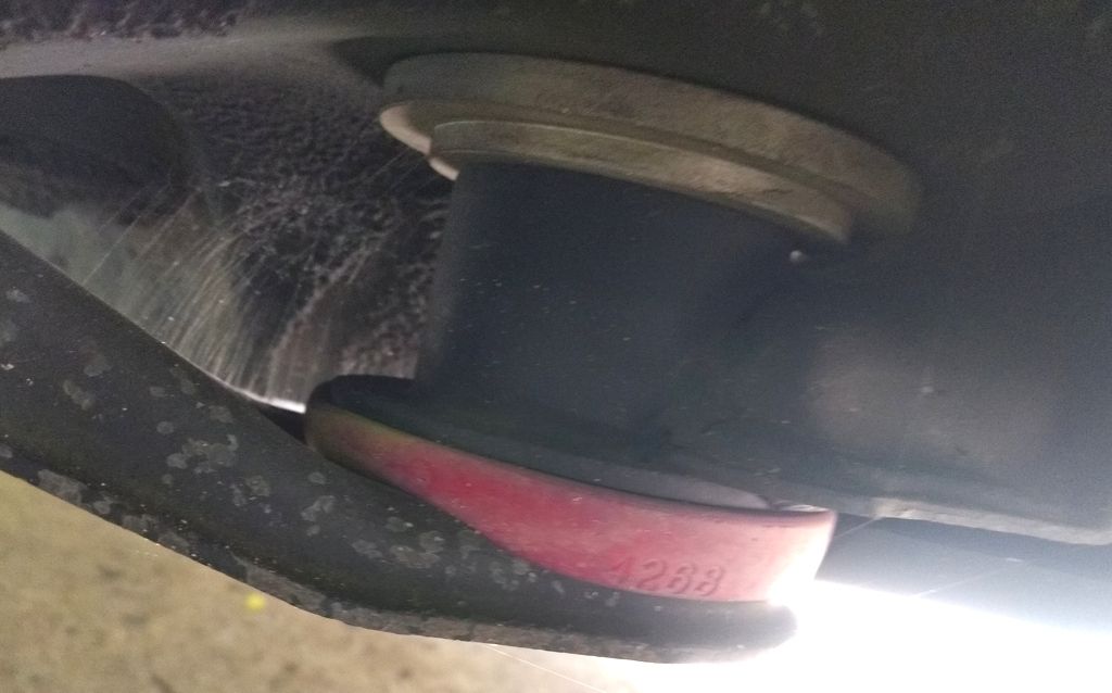
Comparing the Perrin rear lower bushing to the original lower spacer.
Here’s a picture of the new Perrin 4268 bushing that is used on a Subaru WRX compared to the old rear lower spacer. The Perrin bushing is definitely thicker and is capable of absorbing shock that may be transmitted to the rear part of the sub-frame.
Cost Summary
Aluminum 300ZX subframe spacers $25 to $28 depending on color. Shipping free from eBay sellers.
PRG Delrin Titan spacers (set of two) $20 + shipping
Perrin 4268 WRX bushings ~$10 + shipping.
Fastenal 33098 Washers $1 to $2 x 2 = $4 high
Harbor Freight Step Drill Bit $16 (with a 20% off coupon) to $20
Rough Estimate Total $90 to $100 depending on shipping costs.
Parts Sources
Perrin WRX Bushings Part Number 4268
Send an email to Thomas at the following email address: Sales@perrinperformance.com
Approximate cost is $5 each + Shipping.
There is a full set for the WRX that contains bushings that are not needed on the perrinperformance.com site. I was able to get Perrin agree to sell only part 4268 to Maxima owners.
300ZX Aluminum Subframe Spacers
Multiple eBay sellers – Prices vary based by color. Just search for 300ZX aluminum sub-frame spacers and go for the best deal.
Red – http://www.ebay.com/itm/Aluminum-Sub…RYbvZO&vxp=mtr
Silver (I bought silver because I didn’t want a color to get scratched off during installation.)
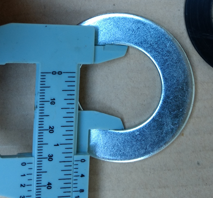
I actually purchased and tried six different types of industrial washers before settling on the on this particular washer. This was the only washer that has the best fit around the inner subframe bushing stalk and matches the 1.250” ID (after bore) on the Delrin Titan spacer.
NOTE: The washer is listed as 1 – 1/8 ID but you can see it actually has a larger ID.
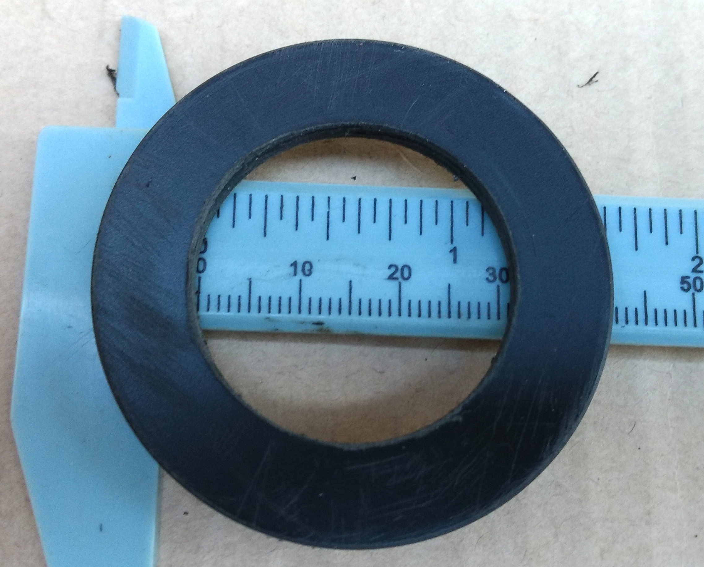
Washer Inner Diameter
Washer Outer Diameter
https://www.fastenal.com/products/details/33098
PRG Delrin Titan Spacers
Approximate Cost $20 for a set of two.
PRG Products Nissan Titan & Armada lower control arm Delrin spacer kit. The factory bushing design has a significant gap between the end of the bushing and the pivot mount. This gap allows the lower control arm to move forward and rearward under braking and acceleration. In some cases this movement leads to a clunk when the vehicle is driven over uneven road surfaces. The PRG Products Delrin Spacer Kit acts as a bushing between these two surfaces which helps to eliminate the gap. By eliminating the gap these spacers can reduce clunking and also make handling more precise.
Update: 2/27/2016 – PerformanceLifts.com has agreed to sell the spacers in sets of two to the Maxima Community for $20.
Until PerformanceLifts.com posts a part number for the Maxima set on their site, you can email Sales@PerformanceLifts.com and reference Maxima.org set (2) of the following part.
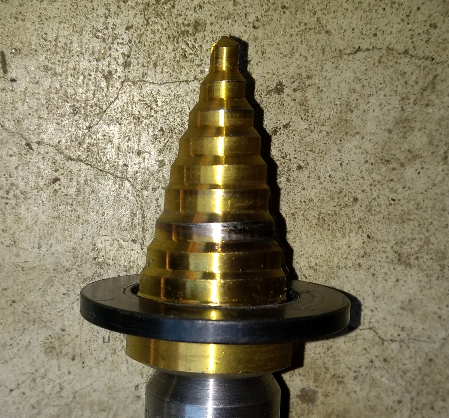
Note the Inner Diameter must be bored out to 1.250″ to clear and fit around the old sub-frame bushing post. I use the Harbor Freight stepped drill bit listed below.
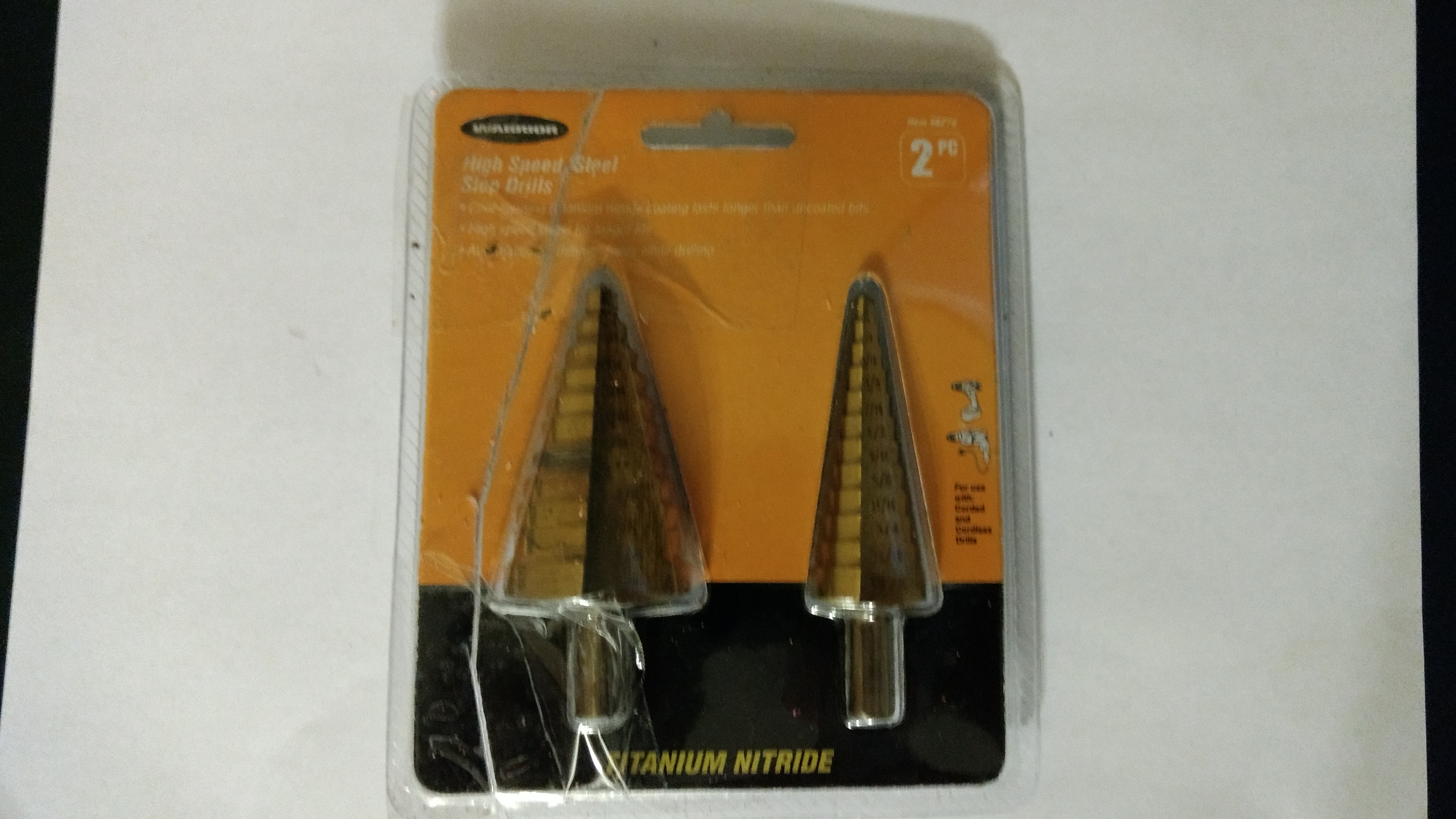
Harbor Freight
Warrior Titanium Nitride Coated High-Speed Steel Step Bit Set 2 Pc
Approximate Cost: $20 – I used a 20% off coupon that brought the price to $16 + Tax
Note: Other methods to bore out the Delrin Titan Spacer to 1.250” or 31mm will work fine.
Use the 1-¼ INCH bit to bore out the Delrin Titan Spacer
http://www.harborfreight.com/2-piece…lls-96275.html
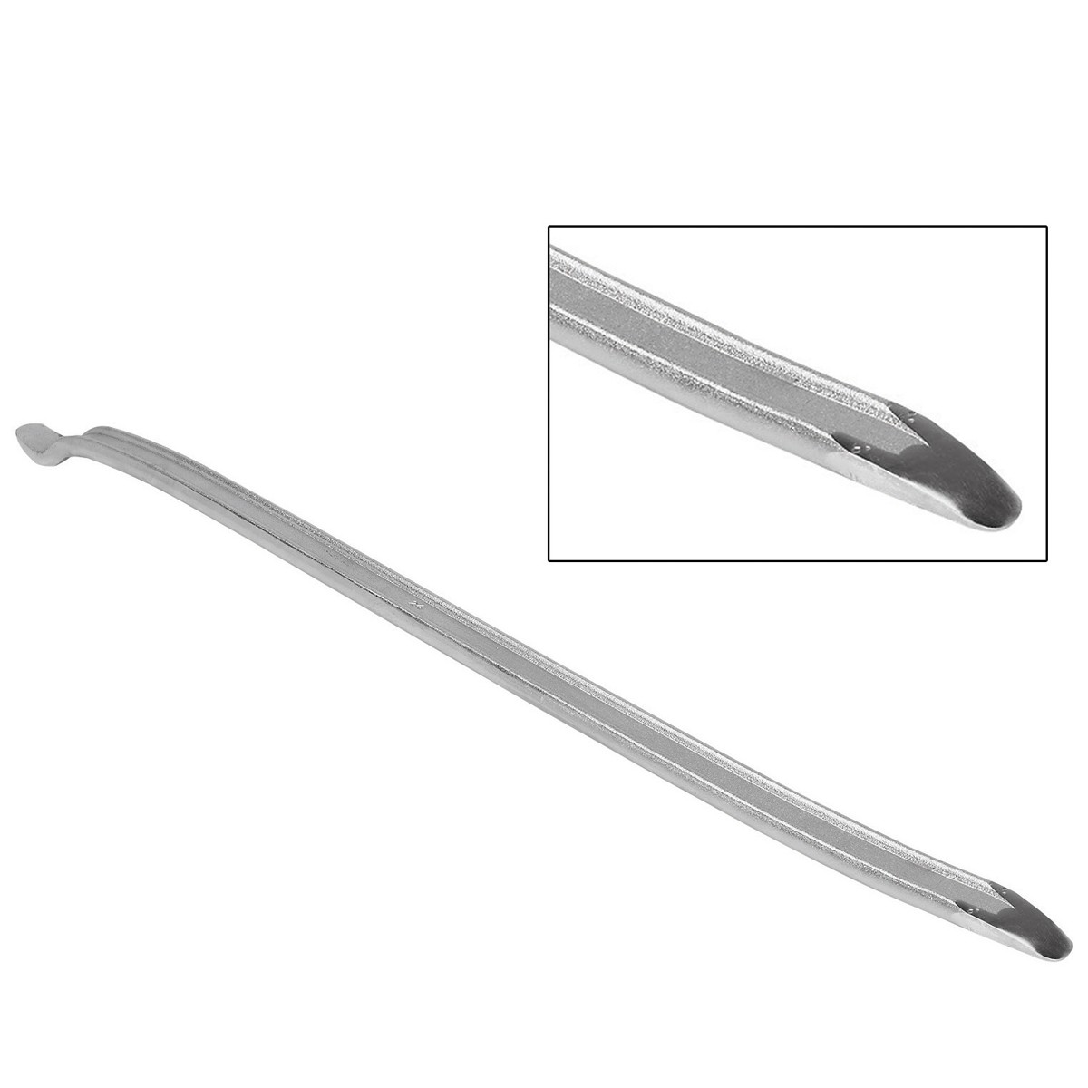
Harbor Freight 24″ Tire Iron
This $5.99 Harbor Freight Tire Iron worked best for wedging in between the rear subframe mount area and the body to “open a gap” so the aluminum collar can be inserted. It came in handy when I needed to push the down on the subframe during installation.
Tools: 19mm socket for sub-frame mount bolts – for SE models there are two 14mm bolts that hold the additional support plate to the body.
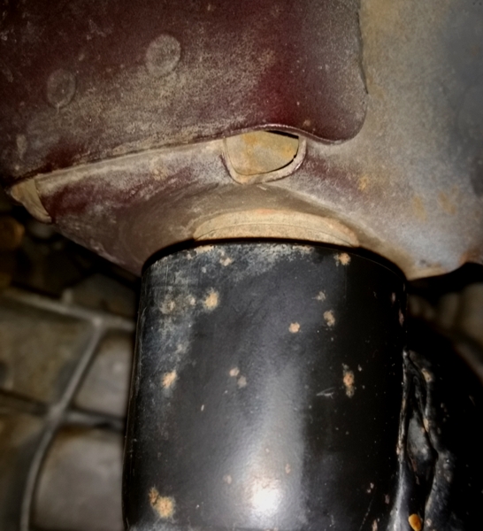
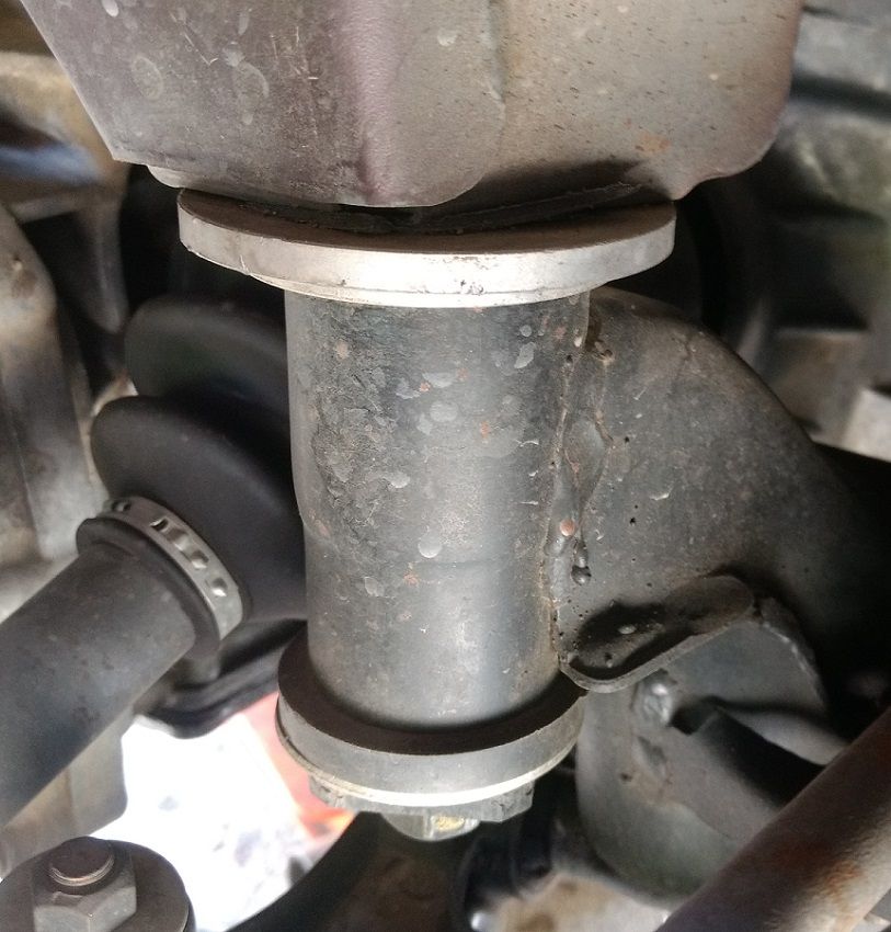
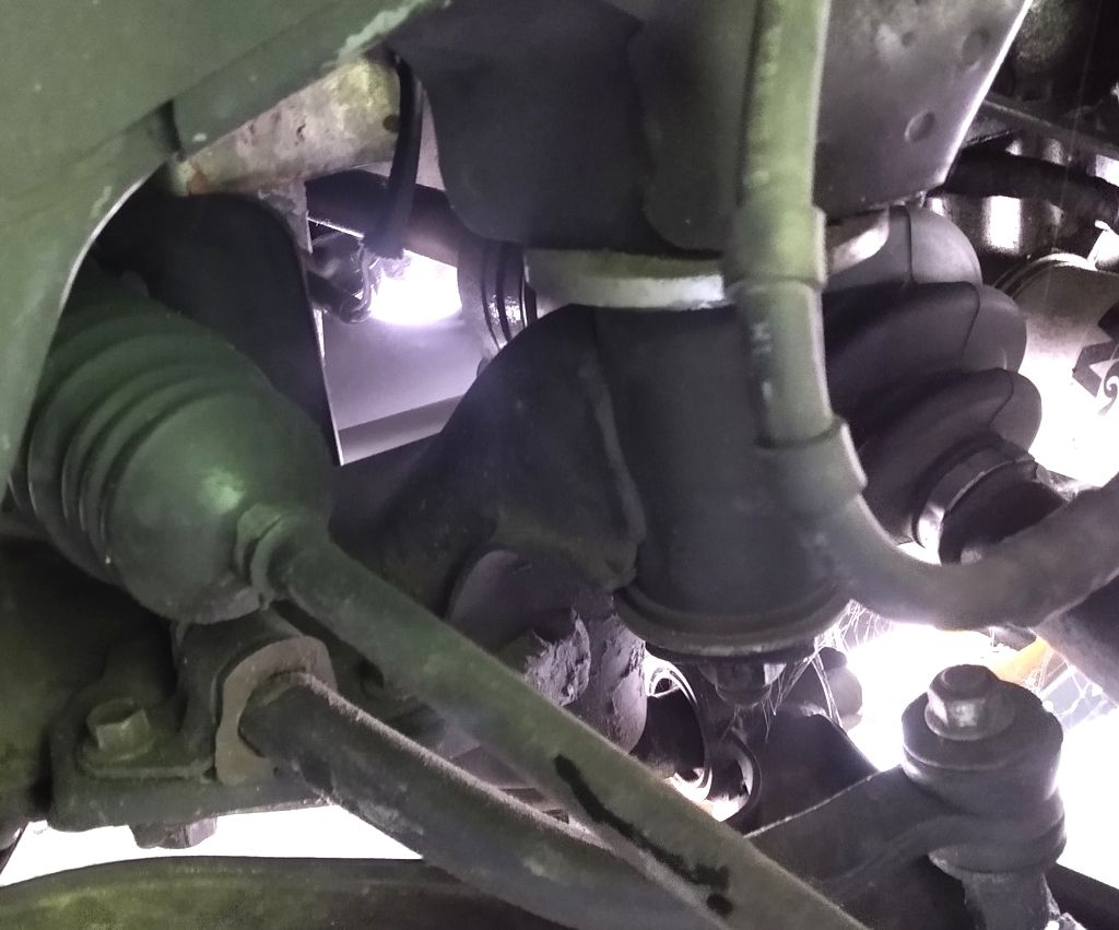
Perrin Bushing Location – SE Suspension
Perrin Bushing Location – non-SE suspension
Rear Spacer
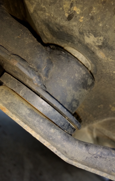
You will need to use a pry bar to push the sub-frame downward and away from the body so the sub-frame collar can slide over and into the sub-frame mount position. Remove both rear sub-frame 19mm bolts and loosen the fronts to provide ample clearance for sliding the aluminum collars into position. This was relatively easy the passenger side but required more effort on the driver side. Where you insert the pry bar depends on the size and length of the bar.
Here’s a picture of the location where I inserted the pry bar at the rear of the sub-frame to push it down so the C collars (front and rear) would slip around the old rubber mount. It is not necessary to cut the old rubber mount or to widen the opening of the C collar after the sub-frame has been pushed down and out of the way using a pry bar for installation. Using this approach allows the new C collars to fit tight around the old rubber post bushing so they will not fall out.
After you slide the new C collar into position, be sure to center the spacer so the most contact is made between the spacer and the upper part of the sub-frame mount post before tightening the 19mm nut on the sub-frame post stud bolt.
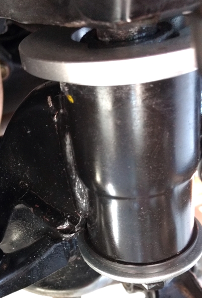
Front Spacer
Like the rear, a pry bar will need to be used to push the sub-frame down far enough for the aluminum collar to clear the sub-frame post. The 19mm bolt and square washer will need to be loosened and removed so the sub-frame post can be lowered enough to allow the collar to clear the upper mount post.
Note on the driver side, I could not get enough clearance for the collar to slide around the post. I used a rubber hammer and tapped the collar into position. Since the inner post is made from rubber, it won’t hurt it. Once the post has been cleared, the collar will be loose for adjustment and final tightening like you see in the picture below.
Note that the PRG Delrin Titan spacers will need to be bored out to an Inside Diameter of 1-1/4 inch.
Use care and wear eye protection when operating a drill and performing this operation to bore out the spacer. How you choose to secure the spacer while boring out the hold will depend on your skill level, and tools available. I used a small drill press vice to hold the spacer in place while I drilled out the ID. I could have used vice grips to clamp the spacer while holding it down. Be sure to stop periodically to clear away shreds of plastic remnants from the sides of the spacer that will appear as you start to bore out the ID.
Disclaimer
This mod should be only used for experimental AutoX track type vehicles that operate on smooth road surfaces where the driver needs maximum feedback from the suspension to make quick decisions while driving a slalom type competition course.
If you drive on rough unpaved roads, cobblestone streets, and traverse large potholes often, then depending on your tire/rim size, you may find the direct feel between the sub-frame and the body to be harsh, uncomfortable, and hard to handle.
For example, this modification on the 98 model with 17″ wheels and 235/45 tires has a completely different feel when compared to the 99 model with 18″ rims and low profile tires. A normal driver would find this modification on the 99 model, with an already stiff suspension, to be too harsh for anything other than smooth interstate driving.
So consider this modification at your own risk.
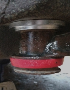
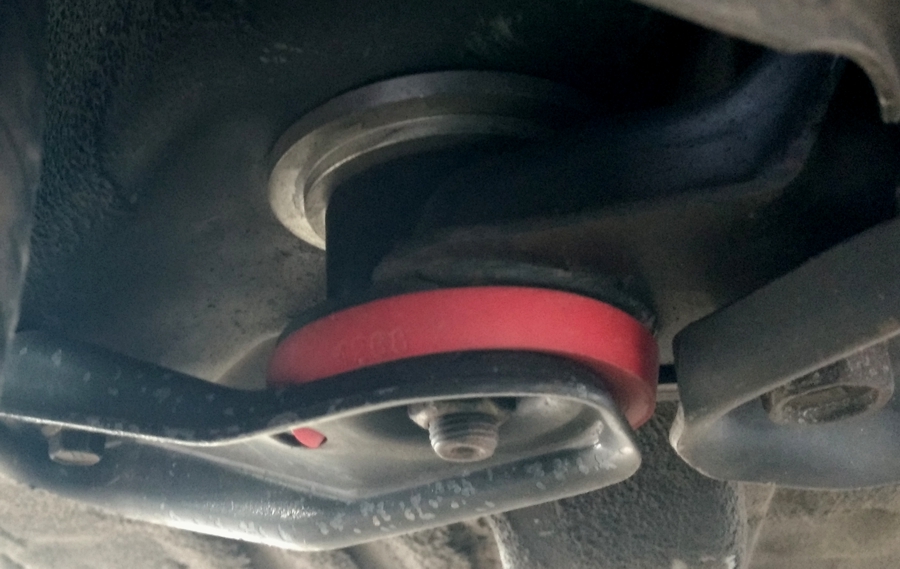
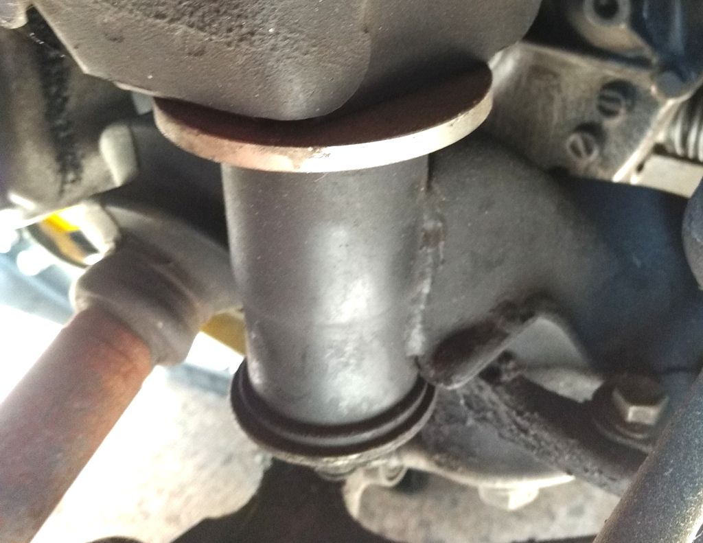
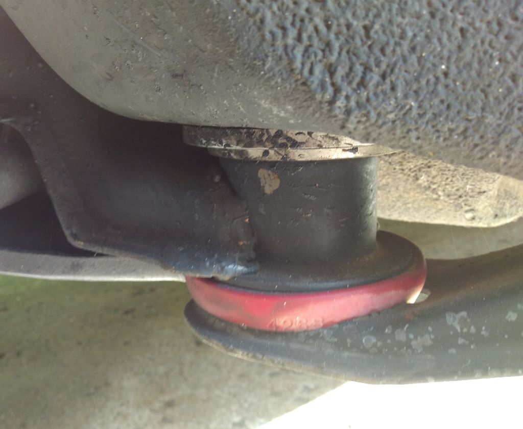
After 5,000+ miles of use on the 99 model SE, here are a couple of pictures to check on on how the bushings are holding up. So far so good.
Rear
Front
Over a year later and we’re in July of 2018. The spacers are still working.
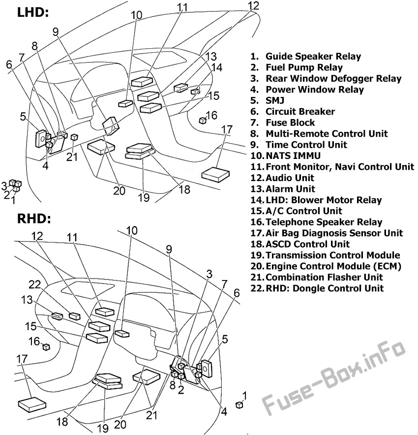
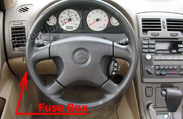
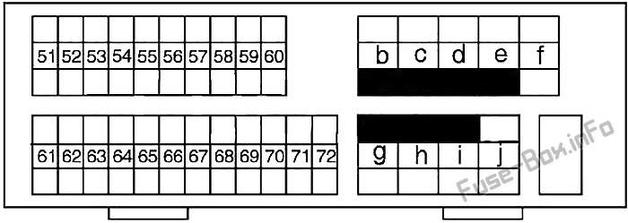
The fuse box is located behind the cover on the driver’s side of the instrument panel.
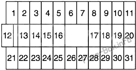
Fuse Box Diagram
Assignment of fuses in the instrument panel
№
Amp Rating
Description
1
10
Steering Wheel Receiver Control Switch, Audio Unit, CD Player, CD Changer, Woofer, Telephone Speaker Relay, Antenna, Telephone Control Unit, Front Monitor
2
15
Stop Lamp Switch (Rear Combination Lamp LH/RH, High-Mounted Stop Lamp), ASCD Control Unit, ABS, Transmission Control Unit
3
15
Trunk Lid Opener, Fuel Lid Opener, Trunk Lid Opener Relay (RHD)
4
–
Not Used
5
15
Hazard Switch (Combination Flasher Unit), Multi-Remote Control Unit
6
15
Front Fog Lamp Relay
7
20
Rear Window Defogger Relay
8
15
Heated Oxygen Sensor
9
10
Heated Seat Switch LH/RH
10
10
Daytime Light Control Unit, Headlamp Aiming Control Unit, Door Switch, Headlamp Washer Control Unit, Height Sensor Rear LH/RH, Clearance Lamp LH/RH, License Lamp LH/RH, Rear Combination Lamp LH/RH, Power Window Switch (Illumination), Power Window Relay, Time Control Unit, Rear Window Defogger Relay, Auto Anti-Dazzling Inside Mirror, ASCD Brake Switch, ASCD Clutch Switch, ASCD Control Unit, Park/Neutral Position Relay, Data Link Connector, Multi-Remote Control Unit, Alarm Unit, Navi
11
10
Transmission Control Unit, Revolution Sensor, A/T Mode Switch
12
10
Key Switch, Time Control Unit, Combination Meter, Clock, Alarm Unit, Security Indicator, NATS Immu, Navi, Data Link Connector, A/C Auto Amplifier, Transmission Control Unit
13
10
Interior Lamp, Front Step Lamp, Door Switch, Time Control Unit, Ignition Key Hole Illumination, Spot Lamp, Vanity Mirror Lamp LH/RH (Illumination), Trunk Room Lamp/Switch, Rear Window Defogger Relay (Door Mirror)
14
10
Combination Meter, Clock, Door Mirror Remote Control Switch, Navi Control Unit, Front Monitor
15
–
Not Used
16
15
Power Socket
17
10
Injector, Fuel Pump Relay (ECM)
18
10
Air Bag Diagnosis Sensor Unit
19
10
A/C Auto Amplifier, A/C Relay, A/C Control Unit, Air Mix Door Motor
20
15
Park/Neutral Position Relay (Park/Neutral Position Switch), NATS IMMU, EVAP Canister Purge Valve Volume Control Solenoid Valve, Swirl Control Valve Control Solenoid Valve, Cooling Fan Relay (1, 2, 3), Variable Induction Air Control System, ASCD
21
10
Daytime Light Control Unit, Engine Control Module
22
15
Cigarette Lighter
23
–
Not Used
24
–
Not Used
25
20
Front Wiper Motor, Front Washer Motor, Front Wiper Switch
26
10
Hazard Switch (Combination Flasher Unit)
27
–
Not Used
28
–
Not Used
29
15
Fuel Pump Relay (Fuel Pump and Fuel Level Sensor, Condenser)
30
10
Combination Meter, Daytime Light Control Unit, Alternator, Park/Neutral Position Switch (Back-Up Lamp), Door Switch, ASCD Brake Switch, ASCD Clutch Switch, ASCD Control Unit, Park/Neutral Position Relay
ECM Relay, NATS IMMU, Throtlle Position Switch, Crankshaft Position Sensor, Front Electronic Controlled Engine Mount, Rear Electronic Controlled Engine Mount
60
10
Headlamp Switch, Daytime Light Control Unit, Headlamp Aiming Motor LH/RH, Fog Lamp Switch, Navi Control Unit, Headlamp Washer Control Unit, Time Control Unit, Illunination Control Switch (Combination Meter, Audio Unit, CD Player, Cigarette Lighter, Headlamp Washer Switch, Glove Box Lamp, Hazard Switch, Navi Control Unit, Door Mirror Remote Control Switch, Clock, Headlamp Aiming Switch, A/T Device, A/C Control Unit, A/C Amplifier (Auto A/C), Ashtray)
61
–
Not Used
62
–
Not Used
63
–
Not Used
64
–
Not Used
65
10
Rear Fog Lamp Relay, Rear Fog Indicator
66
10
A/C Relay
67
15
Woofer
68
15
Headlamp (Left), Headlamp Switch, High Beam Indicator, Dimmer Relay, Diode, Daytime Light Control Unit, Headlamp (Left) Relay (Xenon)
69
15
Headlamp (Right), High Beam Indicator, Diode, Daytime Light Control Unit, Headlamp (Right) Relay (Xenon), Rear Fog Lamp Switch


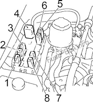
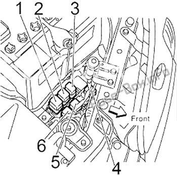
 Fuses and Relays Diagrams")