In this part two of the front mount turbo build I will go over making the radiator efficient enough to cool the engine in all conditions.
Some information about the car:
1997 Maxima
VQ35DE
Automatic
Turbo (initially rear mount turbo)
DIY Fan Shroud
I used a generic brand radiator from eBay. It is a two core aluminum radiator for a Honda del Sol. The fan used is a Spal 12″ Curved Blade Puller Fan. With a pullIng fan it is important to use a shroud so that the air is pulled from all sections of the radiator. Having no shroud the fan will only pull air through the area where the fan is mounted too; limiting the cooling area to that diameter.
I created the Shroud using two cookie baking trays. I cut both of them in half then I overlaid the ends together so that I can have a specific width to cover the whole area needed. The tray is about a quarter inch to half an inch deep which means this is how far the trays floor will be away from the radiator; you want this distance or greater to help pull air from the corners of the radiator.
I then riveted the trays together to make a sturdy. I cut a hexagonal shape in the center with the same diameter as the fan (12″). To support it all, I used the brackets that came with the fan and bolted them to the radiator; I fastened the shroud to the radiator with through bolts.
Dealing with exhaust Heat
For the radiator hoses I visited a local parts store and asked to get access to all the hoses. The tricky part was the bottom hose, so I found several bends that worked out great. I used a connector to merge the hoses together to make one final piece that would go across the radiator support, to the passenger side, and up like the usual stock hose path. This bottom hose passes directly in front of the feed and down pipes so wrapping them in header wrap was necessary in my opinion to protect the rubber from direct heat.
After driving around it was clear that I needed to wrap the down pipe and feed pipe to keep it from starting to over heat; this is when I thought I should have purchased a three core radiator. With a few modifications I have had success with the two core. I created a shield to block the down pipe from radiating heat directly onto the radiators side which helped a lot.
This video shows the heat shield made to block heat from the downpipe.
As you can see in the video, I had the transmission cooler mounted on the grill in front of the turbo. This was an issue because the heat coming off the turbo and exhaust piping would warm up the cooler in traffic. I had to relocate the cooler and at the same time upgraded to a larger unit; more on this in its own blog post.
The next test was sitting in traffic or in a staging line. The engine would start to warm up after a long while. I realized that the reason for this was because the passenger side of the grill area was opened exposing the turbo and exhaust piping. This means that when the car is at a stop, heat comes out of the front of the grill area then gets pulled back in through the radiator; basically the radiator was pulling air that was already hot. The solution was to make a plate from thin aluminum which blocked the left side of the grill completely. I then cut a triangle on the hood above the turbo so that it could be an escape for the heat. The end result gave me a reliable setup for cooling.
Finally, since the car is now more focused for racing, I created a short exhaust pipe that exits out of the hood. This is used for the track or weekends. Alternately I can attach the catback to the original turbo outlet I created when I want a quiet ride. will go into details in the next post.
In the next post I will go over how I created the rear side exhaust while still keeping a muffler.
In this part three of the front mount turbo setup I go over the exhaust options. Exhaust exit to the floor, exit out of the hood and cat back exhaust.
Some information about the car:
1997 Maxima
VQ35DE
Automatic
Turbo (initially rear mount turbo)
Floor Exit
To get the car on the street quickly I made the turbo exit aiming down to the floor. This was not fun like when you drive around the block with no cat back installed and you cant feel your own body due to the noise and drone. The pipe used was 3.5inch and the bend was made with pie cuts for a sharper turn to stay away from the radiator.
Driving required some getting used too. As you drive a car for a long time you start to become aware of the sounds it makes. You can hear when its lean, rich, knocking, or piston slapping. When those sounds are overpowered by the exhaust, you are left with no feedback; you feel disconnected. Apart from that the car was now alive. Here are videos with the exhaust to the floor.
Front mount turbo idling with down pipe aiming to the floor.
Front mount turbo untuned test drive with down pipe to the floor.
Cat Back
I started working on a cat back solution. There was enough space between the cross member and the turbo feed pipe. I had to make a reducer from the turbo to a 3 inch 90 degree pipe. To accomplish this I got the flange for the turbo and made v cuts all around the end that welds to the exhaust. I then bent the fins(created with the V cuts) inward and welded them all; this gave me a smooth reducer. I welded the 90 degree pipe to the flange, welded the other end to a new 90 degree pipe that turns under the engine and between the cross member and turbo feed pipe.
Testing the cat back exhaust at 16psi of boost.
Hood Exit
The hood exist was not my first option, it was not even a thought. With the car not being daily driven I figured I would try something new. I made a 3.5 inch pipe with pie cuts to achieve 90 degrees and pointed it up to the hood. To find where I needed to cut I put grease on the pipe and closed the hood to see where it would mark. After hacking away this is the result.
The hood exit was more quiet than when pointing to the floor. It is still loud but it does not feel like an earthquake anymore.
In Part 4 of this article I will go over the finishing touches, and that is the side exhaust that sounds great.
To be continued…
Thank you for visiting and be sure to subscribe at the top of the page to get the latest from FastMaximas.
This is a topic that a lot of people tend to avoid. They find it difficult before sitting down and trying it or looking it up; its treated like math in a way. I’d like to give an overview of what engine tuning is in layman terms. I will go over an engines mechanics, fuel, timing, sensors and tuning devices.
Engine Basics
An engine is a block of metal that has holes(cylinders) 95.5mm in diameter in the case of a VQ35. Below the cylinders inside the block there is a separate rotating piece of metal called a crank. Inside a cylinder there is a piston that moves up and down, pressurizing as they go up since the top of the cylinder is blocked off by whats called a head. Air and fuel is sent into the cylinder through the head and a spark plug that is screwed through the head and into the cylinder ignites the mixture.
This explosion pushes the piston down into a rod that’s connected to the rotating crank. The stronger the explosions within the cylinders the more force there is to rotate the crank. The crank is connected to the transmission which then sends the torque to the wheels and moves the car.
4-Stroke-Engine.gif: UtzOnBike (3D-model & animation: Autodesk Inventor)derivative work: Cuddlyable3 at en.wikipedia [GFDL or CC-BY-SA-3.0], via Wikimedia Commons
Fuel and Timing
The fuel entering the combustion is controlled by the injectors spray. The rate in which the injectors open and close and the duration while open determines the amount of fuel delivered. The injectors are controlled by the cars computer, the ECU(engine control unit or module). When you hear the term “timing” being mentioned, this is referring to when the spark plug fires and ignites the compressed air and fuel mixture.
As the piston travels up the spark plug fires before the piston has reached the top (TDC – top dead center). By the time the piston reaches the top and starts going down thats when the mixture is starting to fully ignite. The goal is to have the combustion event occur right after the piston reached TDC but not too late that the piston is already traveling downward too far. When combustion occurs before the piston has reached TDC thats when you break parts because the combustion’s pressure will be pushing down while the piston is still going up.
Engine Knocking
Something important you have to know if you care about the longevity of your VQ or any engine. Learn what knocking sounds like. Knocking sounds like marbles hitting each other repeatedly. You may have heard this when putting a lower octane fuel than a car asks for. The higher the fuel octane the higher the pressure it can withstand before exploding therefore more timing could be advanced. That means having the combustion closer to TDC once the piston starts to come down. If the fuel octane is too low for the pressure being generated in the cylinder then random combustion events will occur without the spark plug even firing.
On Maxima’s and most cars, engine knock is detected via a knock sensor that is mounted in the middle of the engine between the two heads. This sensor tells the ECU when knock occurs and the ECU makes proper adjustments in timing to reduce the knocking.
In the next article I will talk to you about sensors and tuning devices.
We have gone over the basic function of an engine, timing, fuel and knocking. Now we’ll start getting deeper into MAF sensors and modifying their signal.
Sensors
The ECU knows the position of the crank by the crank sensor. It knows the amount of air coming in by the MAF(mass airflow) sensor which measures air density. The MAP(manifold absolute pressure) sensor measures the air pressure. These sensors combined help the ECU determine what changes in timing and fuel to make.
Knock Sensor
Like most engine sensors, the knock sensor is very important. This sensor is responsible for detecting knock or random combustion events which generate a pinging/knocking sound like I mentioned before; marbles hitting. You can mimic this sound by tapping the engine block with a screw driver lightly, the knock sensor would pick it up.
When you have a condition that is too lean and or there is too much timing you will tend to experience knock and that is when the sensor sends a signal to the ECU. The ECU then makes timing adjustments such as retarding the timing in order to not repeat the knock it just picked up. On a Maxima, the ECU does not do a good enough job at reducing timing when knock is present, this is why it is important to do something about timing once you start to modify your Maxima for more power. Side note, when you hear a near stock VQ35 knocking, it is likely that there is oil present in the intake manifold and in the combustion due to poor PCV valve design(a catch can is needed).
There are devices that can be programmed to make adjustments to the timing once knock is detected. One system is the J&S Safeguard which is an old school device yet extremely important in the my turbo 97. Once any sign of knock is detected you can choose to reduce certain amount of timing degree’s depending on the strength of the knock. Devices like these do a much better job than the factory ECU which only reduces a small amount of timing when knock is detected. Nowadays standalone ECU’s handle this much better as well as newer factory ECU’s.
MAF
The common MAF has a hot wire suspended in the air inside the intake airflow path. The temperature of the wire affects how much current flows through it. When the wire is hot there is more resistance and therefore less current flows (electrical current moves easier in the cold). The wire is cooled down as air flows through it, reducing resistance and increasing how much current flows through. The resistance measured is converted to a voltage value between 0 and 5.0 which is then sent to the ECU.
You may have heard of the MAF size being increased or swapping to a different one. This is because the MAF is calibrated for a specific air flow and once you start to exceed that the MAF will no longer read additional air.
There are ways to solve this for example once the MAF has maxed out and its sending the ECU 5v, you can then use the MAP sensor to adjust your fuel and timing. Another way could be to increase the size of the housing where the sensors wire is. You can also put a MAF that is designed to read higher amount of air. For my 1997 I use a Nissan Z32 MAF because it is designed to read more air than the factory 4th generation Maxima. The Z32 MAF will read roughly 550WHP worth of air. At about 18psi with a 66mm turbo I see the MAF reading 5v.
Tuning Devices
Engine tuning is controlling the output of the engine by adjusting air, fuel and timing.
Air Fuel Controllers (AFC)
The most common method of making adjustments to the fuel is by using an air fuel controller (AFC). You may have heard of piggyback. This is referring to a device that is connected between the cars ECU and the engine. The piggyback device can be programmed to adjust the signals going to and from the factory ECU. For example if the ECU is sending 50% duty cycle to the injectors, the device could modify that and add or subtract duty cycle. This method of tuning allows you to keep the factory ECU while still being able to tune.
With the common AFC you are limited to being able to control only the MAF signal. By modifying the MAF signal the ECU is receiving, you are able to control the amount of fuel being delivered. This is a great way to make small adjustments to a lightly modified Maxima. One side effect of controlling fuel this way is that when you remove fuel you are increasing timing and when you add fuel you are retarding timing (less timing advance). Technically you can advance timing this way on an all motor Maxima and gain a few HP, as long as the higher timing is not causing knocking; for example ~200WHP/WTQ on an all motor automatic 97.
Advanced Air Fuel Controllers
More advanced air fuel controllers are those that not only can modify the MAF signal but they can modify nearly all engine related signals. For example an Emanage Ultimate can modify fuel injector duty cycle and duration, ignition timing, throttle position, and can read and monitor many inputs. The next level after this would be using a standalone ECU.
Standalone ECU
Standalone ECU’s are computers that replace the car’s factory ECU. This is generally the ideal method of tuning as it gives you total control while the air fuel controllers only modify the factory ECU’s input and output. Standalone’s tend to be far more expensive than air fuel control so generally you see more air fuel controllers used on home built cars.
In the next article I will go over logging and examples.
We have gone over sensors and the type of devices used to tune in part two of this series. Now we’ll take a look at some examples, i’d like to show you what I do to tune.
I would like to note that this is a general explanation of what the tuning process is about and not specific to a tuning device. The same steps can be applied to most systems; the concept is the same.
Logging and Tuning AFR
o2 Sensors
Oxygen (o2) sensors are a critical component to the entire tuning process. They read how much oxygen you have in your exhaust, that is the air to fuel ratio (AFR). 14.7:1 is called stoichiometric and this is considered the ideal mixture of air and fuel in order to have an efficient and complete combustion; 14.7 parts of air to 1 part fuel.
Richer means there is more fuel and Leaner means there is more air and less fuel.
The leaner the mixture is the higher the combustion temperature and therefore more prone to causing damage. Richer means cooler which is why most turbo VQ’s run at an AFR of 11.5:1; not only in VQ’s but most turbo engines in general.
11.5 AFR is only an estimation on turbo, supercharged, and nitrous cars. This is why tuning your engine is ideal instead of using generic tunes from others car.
Tuning
Logging is the most important part of tuning in my opinion. Without it theres nothing you can do but guess what the engine is doing.
First I recommend a track or Dyno for safety. You want to get in a gear that is long but not your highest gear. On a 4 speed auto, 3rd gear is ideal and 2nd gear is long enough to be usable to tune with lightly modified Maxima’s.
Closed Loop and Open Loop
Most of the time the car will be in closed loop below 3k RPM, that means the ECU will be reading the o2’s and making adjustments so that the output AFR is 14.7 for a clean and complete burn. Above 3k RPM and above around 30% throttle the ECU goes into open loop and no longer is using the o2 sensors for feedback. Once in open loop mode the ECU is making adjustments based on tables in the software, usually called Maps.
The MAF and TPS(throttle position sensor) among other sensors are used during open loop to determine the fuel and timing (the o2’s are not used). The 3k RPM and 30% throttle are just estimates and not exact values used by the ECU, there are other factors that determine if the ECU operates in open and closed loop such as engine start up, faulty readings from the o2’s, high coolant temperatures, etc…
On automatic transmissions, the car is ran with over drive off and revved to above 3k before going wide open throttle (WOT) so that it does not downshift; if you go WOT below 3k rpm the transmission will downshift.
Logging and Adjustments
To provide context, I will go over some of the logs from my own Maxima when it ran 11.3 and 11.2 in the 1/4 mile.
For reference below are some details about the car and a video from this day:
1997 VQ35(VQ30 Timing) Automatic.
66mm Turbo at 20-22psi.
Nitrous for launching.
Using an Emanage Ultimate.
The 11.3 run was using all 4 gears.
The 11.2 only 1st and 3rd gear were used; 2nd and 4th gear failed before this run, however the logs still are relevant to our topic. We’ll use the 3rd gear portion of the logs.
Once you’re cruising at your desired RPM such as 3k, you hit record and do a WOT run till redline or the maximum RPM you plan to take the engine to on a regular basis.
Here we have the log to the 11.3 1/4 mile run:
In this log I have selected 6,300 RPM in 3rd gear (the red vertical line). On the right you can see the values for that moment which shows an AFR of 10.5 and 20psi. You want to look at the AFR curve and make sure it is within your desired target AFR, lets use 11.2 as our target.
When your intent is to make adjustments you usually have your tables open such as the fuel table for example. The table shows RPM on top and PSI on the left. So I look at 20psi-21psi on the vertical axis then 6300 RPM on the horizontal axis and where they intercept is the cell that is being used to make adjustments to the fuel. Here we see 22.2%, this means its adding 22.2% to the duty cycle the ECU is giving out to the injectors. Remember that with a piggyback system you are modifying the ECU’s output, its not creating the outputs like a standalone.
So at this moment I am thinking that 10.5 is too rich and I want to make it leaner. I decrease the percentage from 22.5% to 21% in that cell so that it provides less fuel. I look at the rest of the AFR curve and make sure that there are no other areas that are too far off my target; too rich or too lean. You’re ready to do another run after you save your map and export it to the ECU.
Here we have the log to the 11.2 1/4 mile run:
For this run you can now see that at the same gear, RPM and PSI we now have 11.0 AFR. So we have successfully made the AFR leaner by .5. In the case of the Emanage you can see the adjustment value being applied highlighted in blue in the right labeled (I/J Adjustment Map) which is generally the value you entered on your table.
When entering values in the cells keep in mind that the RPM’s and PSI are constantly moving, so the computer may not be using the exact cell you have entered a value for. Instead, it uses the average of the surrounding values (interpolation). For example if you are between 6,000 and 6,300 RPM, the software will use the interpolated value thats between those two cells.
Now that you have seen the change in AFR due to your map change, you can repeat the process till you have achieved your target AFR.
For part 4 and the final part of this series I will touch on tuning the ignition timing.
From my experience VQ35’s tend to have excess crank pressure. Think about it, how many 3.5’s do you hear about that are constantly knocking even with 93 octane fuel and nearly stock with little to no modifications. Part reason is because the inside of intake manifold is coated with oil that comes from the valve cover. Oil in the combustion reduces octane and causes buildup. Why are there so many 3.5’s that leak oil; there are even jokes and meme’s about it. Well, to understand let me take the opportunity and go over the PCV system and solutions.
PCV System
The PCV system is a closed system which circulates the crank case pressure into the intake manifold and back into the combustion; the crank case pressure being generated by the combustion.
Inside the engine, the pistons slide up and down on the cylinder. Oil is used to keep the piston from coming in direct contact with the cylinder wall; allowing it to glide and not rub. The pistons have rings around them which have a gap at one end that allows it contract and expand with the pistons. Part of the rings function is to push/squeegee down the oil that is on the walls to not allow it to enter the combustion. During the combustion some of the pressure escapes past the rings and into the crank case. The crank case is the area below the pistons where the crank rotates; the engine block.
The pressure from the crank case needs to escape, so it flows out of the crank case and into the timing cover area. Then it makes its way up to the heads and out of the valve cover via the PCV valve.
The PCV valve is connected to the intake manifold with a vacuum hose. The intake manifold is constantly in vacuum pulling the fumes from the crank case, into the intake, then into the combustion and out of the exhaust.
Problem
It sounds great to pass the wasted vapors from the crank case back into the combustion. The problem is that these vapors contain oil, so the intake manifold, cylinders, and valves all get coated with oil. This turns to gunk and build up which then can cause increase in compression and knocking. Oil in the combustion may also affect the octane level further causing knock; higher compression, less octane, its not a good mix.
Solutions
Vent to Atmosphere
One option is to disconnect the vacuum line that goes to the intake manifold. Plug the intake manifold and leave the PCV open to atmosphere. Now the intake manifold will not be sucking in oil and the crank case still gets to vent. This is not a clean solution as you are venting that into the air we breathe; when it could have been processed through the combustion again.
One thing that you will notice immediately when you vent to the atmosphere is that it will smell bad. It gets in your clothes and in your pores.
Catch Can
The other option is to use a catch can. A catch can is a container which can be in any shape usually as a cylinder or a square aluminum box. When properly designed, this container is intended to remove the oil from the vapors that come out of the crank case.
You connect a hose from the PCV valve into this container. Then you connect a hose from the container into the intake manifold. As fumes are pulled from the crank case they enter the container and pass through turns and walls to help condensate it. The longer the vapors are out of the engine the cooler they get, then the oil particles become denser and stay in the container. Cleaner air exist the container and into the intake manifold.
DYI Catch Can
DIY PCV Vented Catch Can with a 1/2 Barb.
A home made catch can can be made using a PVC pipe that is closed in one end and with a screw cap on the other end. You can drill two holes then screw in two brass barbs. You fill the PVC with brillow pads. The purpose for the brillow pad is for the vapor to come in contact with the material and add resistance, condensing it. You screw the cap and you connect the PCV hose from the valve cover into one barb and the other barb is connected to the intake. It works better if the barb that takes in fumes has a hose inside that forces it to travel to the bottom of the container. This way is has to make its way up through the material inside and out of the container; otherwise it will enter and leave the container without barely touching the brillow material.
You can also use a catch can with PCV systems that are vented to atmosphere. A hose goes from the PCV valve to the catch can, then cleaner air exits out to atmosphere (it will smell less and keep the engine bay clean). Usually when you have the crank case vented you will notice your hood develop a film of oil and sometime even coat the whole side of the engine bay. Its not cool when you try to impress a girlfriend with a clean Maxima and smells like you drive a tractor.
Turbo and Superchargers
The PCV valve is a one way valve which allows air to flow out of the valve cover. This helps keep pressure from the intake manifold from going into the valve cover and further increasing the pressure of the crank case. When this occurs you will start to see oil leaks develop. The inner timing cover, the outer edges of the timing cover, the area between the inner timing cover and the valve cover, are all areas that are prone to leak because of excess crankcase pressure.
The problem is that these PCV valves do not seal well against pressure. If you have a turbo or supercharger its likely that the pressure from the intake is going to seep into the crank case. A solution is to put a real one way check valve on the hose. The problem now is, where does the crank pressure go if there is pressure in the intake manifold. Generally it will vent out of the front valve cover where a breather is usually placed on the outlet that often connects to the intake piping near the MAF. This is not enough to vent efficiently, the pressure builds up in the crank case till it finds a way out causing leaks and loss in power. If there is pressure in the crank case it takes more effort for the pistons to go down. You can fix this by putting the line that connects to the PCV valve to the suction side of the supercharger or turbo. This is after it has passed through a catch can; you don’t want your shiny compressor wheel coated in oil.
From my experience, when you start to boost the VQ, you need to also vent out more crank case pressure. You can drill out the PCV Valve and use an external one; you can also replace it with a larger one. If your system is vented to atmosphere then you can drill the valve cover, put a barb and run an additional vacuum hose to the catch can. Some catch cans have multiple inlets. You may also have a filter or breather on the front valve cover while you have the check valve in the PCV hose. When the engine goes into boost, it will close the PCV hose, then vent pressure out of the breather. This is not a good solution as you need more flow than just the breather’s port which usually gets routed to the intake.
One last solutions is to run the hoses from the catch can into the exhaust. The hose connects to a pipe that goes in to the exhaust in an angle in the direction with the exhaust stream. As the exhaust flows it pulls the air from the pipe and the hose sucking the crank case pressure out. The closer you have it to the exist of your exhaust the better because if its too close to the engine usually your exhaust system would have some back pressure. So although it would still work it wont be as effective.
There is another solution which is to use a vacuum pump to pull out the crank case pressure but I will not get into those details in this release.
You should now see if you didn’t already how important it is to deal with the PCV system when you modify your car. It directly affects the power of your engine, yet it tends to get forgotten.
In this article I will be going over all the details involved in the rear mount turbo on my 1997 Nissan Maxima.
Being the first to put a rear mount turbo on a Maxima I had to figure out a lot of things along the way. This article will answer many questions that I have been asked over the years as well as address myths that are generally mentioned. The article is organized in the same way and order that I addressed the project:
Why a Rear Mount?
One day I was watching an episode on TV where they showed an installation for a rear mount turbo on a Corvette. During the episode I started to day dream about the maxima being turbo charged and how easy it looked on TV. I reached out to a friend who had a turbo and injectors collecting dust in the garage and decided to go for it. I was a full time college student with no job so the budget was minimal and I had no resources other than a DIY mentality; this is why the rear mount was attractive. I was clueless on how turbos worked as I had never been involved or even driven a turbo car before; I started to learning all the aspects of a turbo system
How a turbo system works?
Basics
The turbo has three parts, the compressor housing, the turbine housing and the mid section. Both the compressor and turbine have wheels that are connected by a shaft which are held by the mid section. The turbine side connects to the exhaust piping from the engine and as exhaust flows from the engine it makes the turbine wheel spin. The turbine varies in size and dimensions internally and produce a back pressure in the exhaust between it and the engine. The turbine housing also has a variety of flanges with different sizes such as T4, T2 or even a V-band nowadays. This pressure forces the wheel to spin with greater force and velocity. As exhaust flows through the wheel, making it spin, it then exists out of the turbo and out to the atmosphere.
As the compressor wheel spins it pulls in fresh air, compresses the air inside the housing and then exist into piping that is connected to the engines intake manifold. Often the compressed air needs to flow through an intercooler since air becomes hot as it is compressed. The turbine and compressor both have similar designs, an inlet and outlet.
The pressure generated between the turbo and the engine is regulated with a wastegate. Think of the wastegate as a bleed valve that releases pressure in a controlled manner. By controlling the pressure thats flowing into the turbine, you are therefore controlling the pressure being generated by the compressor side that flows into the engine’s intake. The wastegate has a spring inside that keeps a valve closed preventing exhaust pressure from bleeding out. The wastegate’s body is connected to the compressor side of the turbo via a hose, this is usually called the boost/pressure reference. As pressure builds up in the compressor and pressurizes the body of the wastegate, this force pushes against the spring and starts to open the valve.
Wastegate springs vary in size and tension which is what dictates the ultimate boost pressure your turbo system generates. In addition to the spring most systems also have a boost controller. Boost controllers are another form of bleeder valve that regulate how much pressure is begin sent to the wastegate body from the compressor. The less pressure it sees the less force is applied against the spring, therefore keeping the wastegate valve from opening fully to the spring’s force. A simple way to think about it is, when the wastegate valve is fully closed, you generate all the boost the turbo is capable of producing, when the valve is fully open the turbo does not generate any pressure since its all being bled out of the wastegate.
One last piece of a turbo system is the blow off valve. The blow off valve allows for the compressed air to escapes out of the charge piping when the throttle body plate is closed. Without a blow off valve when you close the throttle, the pressure generated will need to go somewhere and therefor will push back out of the compressor wheel. In the long run this can cause damage to the turbo’s bearings and in balance in the shafts spin. So as you build boost, you let off, the air pressure escapes; this is the sound you hear in most turbo cars. Often times there are recirculating valves where the released air is sent back into the inlet of the turbo but I wont get into those details here for simplicity.
Turbo lubrication and cooling
The shaft of the turbo is suspended in the middle by bearings, they can be journal or ball bearing. A journal bearing is when a shaft rotates in a surface that contains oil; the oil keeps the shaft from coming in contact with the surface it sits on. Ball bearing is like a the bearings on a skateboard and requires less oil. There are other technologies such as oilless turbos and different ball bearing materials to but these are the basics and as far as I needed to understand.
When using a journal bearing the volume and pressure of oil applied to the turbo is important and checking with the turbo’s manufacture is always recommended to see what the required volume and pressure is. Ball bearings require less oil so a smaller restrictor is needed than a journal bearing, some journal bearings are said to not require any restrictor but I have never come across this with the VQ; we always need one from my experience.
Another function of the oil is to cool the turbo’s center section; some turbos are also water cooled where they connect to the cooling system of the engine.
The Rear Mount Turbo
Now that we know how a turbo works lets get into the details pertaining to the actual rear mount turbo configuration.
After laying under the car for some times and brainstorming where the turbo should fit best I decided to locate it where the muffler is. I unbolted the muffler and cut off right after the rear beam, then had a local muffler shop weld a T4 flange using the turbo to mock up. Once I was home, I then bolted up the turbo.
Rear mount turbo maxima no muffler.
The turbo air filter I used was a large 4inch open K&N. I had to hammer in the spare tire well so that the filter could fit however that is not necessary as there are filters that have a much lower profile. I had a few ideas for locating the filter including having it inside the truck, or routing it to the driver side. I tested putting the filter in the trunk while having an additional hole for fresh air to come in. The hole I made for the fresh air to come in was not large enough so with the windows closed when the turbo would go into full boost you could feel the negative pressure in the cabin; not good. At the end I kept the filter like shown in the picture for years and never did I have issues with water. This car was driven daily in Miami where it is raining often.
Oiling the turbo in the back.
I purchased a generic eBay sandwich plate that has 4an ports, added a 4an fitting and then connected a nitrous line (what I had at the time). I routed the line on the passenger side of the bottom of the car using zip ties to hold in place.
Sandwich plate(blue) for turbo’s oil feed and oil cooler plate.
On a traditional front mount turbo setup the oil feeds the same way, but the drain or outlet of the oil from the turbo goes back into the engine via gravity; most front mount turbo’s are located above the engines upper oil pan. Since I did not have this possibility I needed to figure out how to get the oil from the turbo back to the engine.
My solution was using a Shurflo 8000 series scavenge pump that is generally used for water, such as in RV’s for sinks or other uses. I decided to use this after having long conversations with someone in the Cavalier Z24 community that was also working on a rear mount turbo. I used an 8an line that connected from the turbo, into the trunk (by the spare tire well) and into the pump. The pump outlet had a 3/8th hose that came out of the trunk by the driver side of the car, over the rear beam and to the front of the car beside the fuel line. At the front of the car the line then came up over the transmission toward the front valve cover and then to the oil cap. I bought a metal oil cap then I drilled, tapped and screwed in a 3/8th barb which is where I connected the hose. I also had a clear glass inline fuel filter without the insides so that I can observe the oil flow for testing and diagnosis.
Scavenge pump for turboOil return from turbo
Oil problems
Oiling was the most challenging part of this project because I had to deal with regulating the flow going to the turbo in coordination with how well the pump removed oil from it. If you feed it too much oil, the pump may not be able to pull it fast enough so then the oil builds up pressure in the mid section and leaks out of the turbine housings. I quickly learned that blue smoke on vehicles usually means that oil is being burnt (white smoke being coolant, black smoke being fuel).
Part solution was using an oil restrictor. These restrictors are sold specifically for turbos but being on a budget I had to work with what I had, and that was using nitrous parts. For the Garrett T04b, I used 4an fitting, cut off the flared part that connects to the hose and put a nitrous jet in its place where I then drilled a 1/16th hole; this gives you an orifice size of 0.063.
This helped stopped the turbo from smoking and i was finally able to drive around with it but there were more complications.
I noticed that when the car was at a stop and then I started her up, smoke would come out again. The reason was that while the car was turned off, the feed line to the turbo continued to drip oil into the turbos mid section and then leaked into the housings. I fixed this by putting a check valve that required 1psi of pressure to allow fluid to pass, with the car off it no longer leaked.
Another issue was that even with the pressure check valve in place it would smoke. The reason for this was because the pump was wired into the ignition. So when you turn off the car, the pump does not have time to pull all the oil collected in the line and turbo; this causes it to leak into the housings. The solution was to leave the pump running on a turbo timer for a few seconds to clear out the line. I used a generic eBay turbo timer for this.
The last problem I had was when doing long highway runs where the engine was at high RPM’s for an extended period of time (for example a 1/4 run) the pump was not able to keep up with the oil delivery. I ended up adding a second pump using a T on the line for pulling from the turbo and another T on the line that went to the front of the car. This was the last step needed to not have any oil issues again. This process was all through discovery by trial and error so doing this again would be very simple.
Turbo Charge Pipe
Initially the turbo charge pipe size used was 2 inches. It was out of steel as it was the quickest and cheapest option available for me. For bends I used heater hoses and worm gear clamps. I routed the pipe from the turbo to a 90 degree turn towards the drive side, then a U bend over the beam and towards the bottom of the gas tank. From the gas tank I ran a straight pipe beside the fuel lines and oil line to under the transmission, then a 90 degree turn up where the blow off valve was placed, then another 90 degree turn that routed towards the intake manifold. This initial setup was without an intercooler and the initial boost pressure I went with was 6psi.
Intercooler
At first, I did not use an intercooler for simplicity. Eventually I purchased a methanol and water injection kit (there will be another article about this) because I quickly started to pick up engine knock. There is this common misconception that by having a turbo mounted in the rear, you no longer need an intercooler; this my friends is completely false. I was able to push the system without an intercooler up to about 10psi with the methanol and water injection. Without the intercooler at 10psi I achieved 299whp and 291wtq, at 6psi it made 250whp and 242wtq.
I routed the charge pipe from the turbo by going under the transmission, then a bend that turned towards the passenger and between the radiator and the front engine mount. Then the pipe continued to near the fog light area where it turned towards the radiator support and through it (after drilling a hole through the support). Then a bend into the intercooler and on the driver side the pipe exited and turned into the support back towards the engine bay. Then the pipe turns upwards with the blow off valve in place behind the fans and then towards the MAF and throttle body.
Rear mount turbo manual maxima intercooler piping.
I then upgraded to an intercooler with the size of 28X5.5X2.5 and the inlet/outlet were 2 inch. My temperatures before the intercooler on average were 130’s F during boost. After the intercooler installation the highest temperature I saw was 111 F. This was on typical Miami summer weather so likely in the low 90s or 80s.
With the intercooler, I at the same 10psi it made 312whp and 301wtq.
T04b 10psi and 6psi Dyno, non-intercooled meth/water injectionT04b 10psi and 6psi Dyno, intercooled meth/water injection
Upgrading to 2.5 inch Charge pipe
Over time I felt that the 2 inch charge piping was a limitation, so I purchased an intercooler piping kit from eBay for 2.5 inch diameter. I then pressed them into an oval with 2/4 pieces of wood and a mallet. This was the pipes that went directly under the car between the gas tank and the engine.
The performance gains from upgrading to 2.5 inch was drastic in all aspects. Spool up was faster, the mid and top end of the RPM performance were significantly improved. The 2 inch piping which I believed would have improved spool up due to more velocity was actually a big restriction. I recommend starting off with a 2.5 inch charge pipe from the beginning.
Exhaust Piping and Spool Up
From the engine to the turbo I already had a 2.5 inch y-pipe and a 2.5 inch cat back. One of the most important parts of the whole system as far turbo performance and response goes was to wrap the entire exhaust with header wrap. I wrapped the y-pipe and the cat back; this improved the spool up of the turbo. The next improvement was removing a 22 inch Magnaflow resonator. I found that even though the resonator was completely straight through, it slowed spooled up by a lot. This could be because the resonator could have been functioning as a heat sink absorbing a lot of heat and therefore slowing down the velocity of the exhaust. With the piping wrapped and no resonator the turbo responded just like it would on a front mount, at the time I had no way of logging so I did not record data for this, but it was a significant improvement.
I then had the muffler shop route a straight pipe from the turbo to the factory muffler tip location. This picture below shows another rear mount turbo maxima where the same straight pipe was done.
The next step was to figure out what to do about the sound, it was very loud and being automatic it did not make for a good daily driver like this. I went to the local muffler shop where they put on a bend out of the turbo near the tire, then into a muffler. At first the bend was crushed style but we all know this is not acceptable so eventually I upgraded to a mandrel bent outlet.
I now had a turbo rear mount maxima that was quiet and performed really well. I drove this car for years with this setup and raced it a lot. Here are additional photos showing how one can route the piping on the 4th gen Maxima.
First 1/4 Track Time as a Rear Mount Turbo
With the TO4B turbo, boosting 7.5psi non-intercooled, a 2000-2001 Maxima intake manifold, and an APEXI VAFC2 for tuning the fuel, this is what the car ran in the 1/4 mile.
My previous best time was with the 75 nitrous shot and I ran a 14.2@98mph with a 2.3 60′. The turbo at 7.5psi was putting down more power than the 75shot.
In the next article I will continue to discuss the rear mount. I will write about a different solution for the oil system among more details regarding the rear mount. Thank you for reading and feel free to comment or ask questions that were not covered so far.
Rear Mount Turbo VQ35 Swap
After racing the VQ30 a lot I eventually needed to replace the head gasket. Since this was my first experience tuning a car, the engine spent a lot of time knocking initially. I wrote an article about my tuning experience here. Over time I noticed that at 10psi the coolant reservoir would over fill, this meant that the head gasket was starting to fail. I then replaced the gasket and continued pushing the VQ30 passed 10psi. The engine started to also develop additional blow-by because the rings were not sealing properly. I believe these failures were due to my tuning experience, I am not upset nor do I regret this as this was part of the learning experience for tuning a turbo car.
I then did the VQ35 swap while using the 3.0 timing equipment. The engine I used was from the junk yard and only lasted about two weeks before a rod broke. When I finished the swap I always noticed a feint tapping sound and VQ’s being noisy engines I somewhat ignored it but still acknowledged it (maybe I was in denial). Then while cruising down the highway without putting it through any abuse the tapping turned into a loud knock which eventually went silent. The moment it went silent I knew something was about to happen and then BAM, a rod broke. This is why I will never trust a junk yard VQ engine, specially since we are seeing blow VQ35’s being a trend now when put under some significant boost. My decision was to build the bottom end of the VQ35.I will write an article about it because it was a fun journey where I learned a lot and I know many of you will find it valuable.
Most of the videos I have as well as races at the track as a rear mount turbo were all with the built VQ35.
Stock VQ35DE Broken Rod compared to an Eagle H-Beam Rod
Turbo Compressor Surge
Something I experienced was what they call surge (flutter, among many other names). That is when you let off the gas, the throttle closes, and the pressure does not escape out of the charge pipe fast enough causing the pressure to back up into the turbo compressor wheel. The sound produced to some may be cool, but it is not good for the turbo, some turbos are designed to handle this but its better to not have this at all. This cause throw off the balance of the wheel and shaft. The blow off valve that I had was not able to vent enough so when I would let off you could hear the flutter (sh sh sh sh sh sh). I am not going to lie, I loved the sound. What I did was add a second blow off valve to the back near the turbo, then a hard line coming from the valve to the intake manifold. Now when I let off the gas, both blow off valves open venting the charge pipe immediately.
I also learned that it was important for the blow off valves to have a good source of vacuum, and having a line that would not flex or collapse. This way the response and volume pulling the valve open would be greater. A thin line with vacuum is far weaker than a large line with vacuum.
Self contained oil system for the rear mount
One thought I had was to have a self contained oil system for the turbo. This is when the turbo oil is fed from a tank through a pump. The pump pulls oil from a tank, sends it to the turbo, the turbo then drains the oil back into the tank. I spent a lot of time thinking and planning this out but at the end of the day, it was not worth the effort. You have to take care of cooling the oil because with every pass it gets through the turbo it is heated. You also had to possibly vent the tank.
Now the tank or container can be below the turbo so that the drain naturally flows into it, but being a rear mount turbo means that the turbo is already pretty low unless you have it way up in the bottom of the car. This means you would need two pumps, one to pull oil from the turbo and feed it into the tank, and another to send the oil back to the turbo. Now you have to take care of the pressure being sent to the pump and regulate it. All this was too much trouble to really have little benefit in my opinion. Having a line from the engine to the turbo, then a line from the scavenge pump to the engine was far simpler and effective; possibly even cooling the oil on the way back (although I didn’t do it with this intent).
What are the costs involved?
A turbo can be had for any price to be honest. I started off with a hand me down which was a T04b T4 .69ar turbine turbo. Then I got a genuine Holset HX35 for less than $300, and eventually ended up with a Holset HX40Pro Replica for also less than $300. I put a lot of miles through these turbos, over 100k miles on the first engine build and the only issue they had was due to user error when I made a mistake that caused the oil feed to be restricted, running the turbo dry. Here is what that sounded like:
And this was the damage:
I mention this failure in this section because once you turbocharge a car, you will have issues come up, specially if it is the first turbo system you have worked with. So yes you can have an initial parts list all priced out but you also have to think about what could come up later on. Now lets get into the parts list.
Parts List
The parts list would be the same as a front mount turbo.
Turbo ($300-$2000)
Wastegate ($250-350): I did not want to go cheap on the wastegate as it is an important piece, I got a Tial 38mm.
Blow off valve ($25-$200): this I did go cheap with and I used an Turbo XS RFL which was very loud and fun to have, however by design they leak since they do not have a diaphragm, its a metal piston that does not seal completely.
Scavenge Pump ($100-$200): I used a Shurflo 800 series pump, two of them. A gear driven pump is said to be better for this occasions, those go for about $400-$600 at the time I was looking. ebay has them nowadays for less than $100 but I have no experience with them.
Intercooler ($100-$300): I started off with an eBay intercooler, then upgraded to a better quality one.
Oil Sandwich Plate ($10-$30)
Stainless Steel Braided Oil line ($20-50): I used a 4an nitrous line.
3/8th oil line (transmission line works): This line is for returning oil to the engine as well as pulling from the turbo and into the pump.
Charge pipe ($80-200), that can vary greatly depending on how you go about routing and material.
The rest is miscellaneous parts and labor such as welding, flanges, gaskets, etc…
Turbo sizing specific to the rear mount
After using the T04b turbo, I then moved to a Holset HX35 turbo. I did research on the Holset’s and saw that one of my favorite platforms (the DSM’s) used them a lot. I got on eBay and came across a brand new genuine unit for about $235, I had to get it.
The HX35’s are ideal for mid 300whp, once I wanted to make more power I went for an HX40Pro. The Pro means it has a larger more efficient compressor wheel that helps produce more power. These turbos come with a large turbine housing with over 1. AR (18cm^2). They do not spool very fast but work great overall. I saw that the DSM community likes to put a T3 .70AR Bullseye turbine, now this my friends really transformed the performance of the car; the turbo spooled immediately.
This is how the turbo performed with the large Holset 18cm housing before the Bullseye housing.
This was my reaction on the maxima forum after putting the Bullseye .70ar housing: “Got the .70AR housing installed and HOLY F***. I can get full boost in 1st gear (15psi, even with no load while spinning lol). in 2nd and 3rd boost comes in like if it was a nitrous shot, full boost at about 4200, spools up then BAMMMM no turbo sound or anything straight up WG dump and pshhhhhhhhhhhhhhhhh. LOL. pretty wild. It spun the tires at around 60ish in one instance.” ; you can see I was overly excited with how well the turbo responded.
Bullseye .70ar T3 vs. Holset 18cm^2 (~1.00ar)Bullseye .70ar T3 vs. Holset 18cm^2 (~1.00ar)
As you can probably notice, most of the build was on a budget, I did not have the freedom to shop for different turbos. However, I did come to a conclusion. VQ’s do not like T3 turbines in my opinion, VQ’s flow a lot of exhaust and require a T4. The T04b T4 turbo I had at 16psi on the VQ30 outperformed the VQ35 with a T3 Holset housing. Let me show you what led me to conclude this, observe this dyno chart below.
Holset 18cm Turbine Turbo at 14psi and 18psi.
Do not let the dyno numbers mislead you, this is about mid to low 400’s, they show as 300’s because the dyno was done with the torque converter unlocked (this is why I do not dyno very often, they do not add any value other than a safer tuning environment in my opinion). Notice that around 5500 RPM both dyno runs end up at the same power and torque output roughly. One was at 14psi and the other was at 18psi yet they both choke at 5500 RPM. I did a lot of research and asking around and concluded that the T3 housing was the cause. So my advice to you is, start with a T4 turbine and forget about being able to spool quicker with one, once you get the urge to gain more power you’ll regret having used a T3.
Here’s the video of the Dyno. I never recorded a video with the Bullseye housing but it was about 1,000 RPM sooner in spool up with it.
What would I do different from the beginning?
Nothing, my experience led me to learn all aspects of the turbo system and near the end of the rear mount turbo journey I feel I had perfected it. I have no doubt that had I kept the rear mount and used the proper size turbo, it would have performed as well as my front mount does; you can read about the front mount build. https://www.my4dsc.com/streetzlegend-front-mount-turbo-build-part-1/
Rear Mount vs. Front Mount
After years of using the rear mount I eventually changed to a front mount turbo. I have been asked many times why did I make this change if the rear mount turbo worked well. My first reason was because I wanted to learn how to weld so I decided to fabricate my own front mount system. The 2nd reason was weight reductions, getting more serious with racing meant weight needed to be addressed on an already heavy automatic GLE Maxima. The rear mount turbo specific parts were 80lb’s in total in comparison to the front mount. Although there were benefits in going with a front mount turbo it was never a thought nor a plan todo so. I received a welder as a gift, the maxima was no longer a daily so I jumped into putting together a front mount.
When I changed to the front mount using an HX40Pro Holset turbo the spool was similar. At the time I had a .70ar T3 Turbine housing which meant the turbo spooled up very fast both in the rear and the front. I have come to the conclusion that the difference between having the turbo in the front vs. the back does not affect the spool up as much as one would think.
Would I do another front mount? Absolutely yes, I still want to see what a rear mount turbo setup can do with a proper size turbo and I know some of you are working on it or are planning too, so I am excited in sharing this information with you.
I believe my best was 12.8 at 117MPH in the 1/4 with Holset turbo at around 20psi
In this article I will go over some of the tips and tricks that I have applied in order to keep the automatic transmission from failing, or prolonging it at the very least.
Torque Converter and Fluid
Lets start with the fluid, the transmission fluid is one of the most important parts of the system, it is used to transfer the engines output to the wheels. The engine spins a large drum called the torque converter. The converter is bolted to the flex plate (it is like the flywheel on a manual car), which is connected to the engines crank. The converter has an output in the center which connects to the transmission; this output is physically separate from the housing. An example of how the converter works is when you put two fans facing each other and you turn one on, the other one will spin. Of course the internals of the converter are more complex but it is the same principle.
You can start to see why you are able to have an automatic car in drive while at a stop, yet in a manual car the engine would stall if you left it in gear and stopped. This is because at low RPM’s the converter is not spinning fast enough to cause the opposite side (the output) to spin and propel the car forward, this is called the stall speed; it is the RPM which the engine begins to stall due to the transmissions resistance. Typically on a factory car like the Maxima the stall speed is around 1500 to 2500 RPM. In racing conditions where you want to launch the car as quick as possible, you want to do it from a high RPM. This is when you hear “high stall torque converters” being mentioned. With a high stall converter, the internal fins are modified and angled so that the RPM needed to move the car is higher.
You may think that you can put the highest stall possible but this comes at a cost. The higher the stall the less efficient the converter may be because there is less room for the converter to couple before the rev limit. The coupling is when the input and the output of the converter are spinning at near 1:1 ratio. The lower the RPM the less coupling, the more the RPM the more coupling and more torque is transferred to the wheels. Having the stall too high may give a similar symptom as when you drive a manual with a slipping clutch, you never get the full engagement.
Lock up converter
Torque converters have the option of a lock up clutch that engages using a solenoid on the Valve Body. When this clutch is engaged the converters input and output are locked together functioning just like a manual clutch. With a 1:1 ratio all the engines torque is transferred to the transmission. The ideal torque converter is that which gives you the highest stall possible while coupling still within the engines most usable RPM range. Using the lock up clutch may not be ideal depending on the application; they may not be able to hold the torque on higher HP/TQ. On a high quality converter the coupling should be enough to where a lock up clutch is not needed. Usually the lock up clutch is used by factory during cruising conditions. You may notice the sense of an extra gear when you come to a cruising speed at 40mph to 60mph, this is because the clutch engages and RPM’s drop for better gas milage. Also at wide open throttle with the shifter in Drive and the OD Off (light on the dash turned on), this will keep the transmission in 3rd gear and also lock the torque converter; you can play around this to get a better feel for it.
A 3,000 to a 3,500 stall is usually ideal for most Maxima applications.
Fluid
Keeping the fluid temperature under control is critical. The transmission not only uses fluid in the torque converter but uses it in the entire transmission. Fluid flows through a central location called the valve body. The valve body is what directs the fluid through passages using solenoids to output to the necessary clutches and bands for the selected gear. In factory form, the transmission a has fluid hose output that goes into a bottom chamber of the radiator, exists and then returns to the transmission. This is great to warm up the transmission during cold starts as well as keeping the temperature from overheating by being influenced by the coolant temperature. The problem is that when the torque is beyond what the car came with, you are increasing heat, the radiator’s transmission chamber is not good enough to keep the temperature down.
An external cooler is then required, in my opinion this applies to even maxima’s that are kept in stock form. It is well known that heat is one of the main causes of failures, so why not address it immediately. The external cooler choice varies, I always say to get the largest cooler you can fit. If you live in an environment where freezing temperature are expected it is always a good idea to use a thermostat combined with the cooler.
97 Maxima automatic transmission fluid inlets.
In this picture above, you can see the inlet and outlet of the fluid. The large banjo fitting is the outlet and the hard line above it is the return. The hose used is a 3/8th transmission hose.
Tru-cool cooler with two spal 9in fans.
The cooler I used is a Tru-cool that is rated for 40,000 GVM (gross vehicle mass) and is generally used in RV and Towing applications. Mounted on the cooler are two Spal 9inch puller fans which I have mounted on a switch using relays.
You can find the cooler and fans on amazon.
Cooler: https://amzn.to/2LJRu8v
Fan: https://amzn.to/30XaTXm
Clutches
Inside the transmission there are severals drums with shafts going through them that spin freely independent from the body of the drum. To help you think about this imagine a rod connected to the engine which goes through a drum. The body of the drum is connected to the wheels. So the engine and the wheels are independent because the engines shaft spins freely. Now if you were to connect the rod with the drum then the wheels would turn. In the drum there is an alternating stack of disks (or clutches. One set of clutches is connected to the housing while the other set is connected to the shaft. When you press them together the friction binds them so the shaft and the drum spin together transferring the engines torque to the wheels. The clutche pack is submerged in fluid which allows for an important function. It keeps the disks from burning by keeping them lubricated and gliding against each other till they are pressed together; rubbing your hands dry vs. rubbing them with soap. This is called viscous coupling, where fluid is used to transfer torque. When you press the plates together using hydraulic pressure, the plates will slip till there is enough force and resistance to make them connect. During this engagement a lot of heat is generated, so you want to engage as quickly as possible to not stay in the slipping stage too long.
Driving Habits
To extend the life of the auto I go by a couple of rules I set myself. Never go wide open throttle from a roll while the transmission is in a higher gear. Putting load on the transmission while it is downshift is very rough on it. It generates a lot of heat because there is more slippage in the clutches. It is better if you manually downshift to a lower gear before going wide open throttle.
When driving and racing I like to keep an eye on the transmission temperature. I like to keep the temperature below 185 at all times. You will notice that while in traffic the temperature will start climbing up, this is because the converter is constantly spinning trying to get the car to move but you are creating resistance by being at a stop; this produces heat. I sometimes prefer to put the car in neutral when at a stop for a long time such as a staging line at the track or traffic.
Modifications
Drop Resistor Mod
This popular modification is also very important because it increases the fluid pressure that the transmission uses internally. This means that the clutches in the transmission are pressed together with more force and therefore providing less slippage and more engagement. Usually factory cars come with a certain amount of slip in order to provide for a smooth comfortable ride, but since we want to go fast here we want the most clamping force possible..
The drop resistor modification is simple, there is a resistor that is mounted on the driver side strut tower in the engine bay on 4th gen and 5th gen Maxima’s, (6th gen perhaps?). When this resistor is disconnected, the transmission then will use 100% of the fluid pressure available. Since disconnecting this causes higher pressure and we want this, you can get a throttle switch that is Normally Closed. The switch can be placed at the throttle or below the gas pedal. You want to activate the switch when you are at open throttle, this will disconnect the resistor. You do not want to disconnect the resistor all the time or at low part throttle because you will have a violent shift that may cause some damage. Note that your overdrive lights will flash when the resistor disconnects at open throttle; the light and code will go away over time and does not affect drivability.
Valve Body
The valve body is responsible for the behavior of the transmission. Attached to the valve body there is a pack of solenoids. In the pack includes two shift solenoids (in the case of the 4 speed Maxima), a fluid pressure solenoid, a torque converter solenoid and and overrun clutch solenoid. When it comes to modifications you have the option to upgrade the VB yourself using a Transgo shift kit. There is the HD and HD2, the later being a more aggressive change in the shifts. There are passages that are drilled as well as ball bearings and springs that are changed to affect the pressure the clutches in the transmission are getting.
Another option is sending the valve body to a transmission shop for them to upgrade, there are common modifications done to automatic performance transmissions so most auto shops should be able to do this.
The solenoids are sometimes also upgraded, they are modified to increase the amount of fluid that flows through them which help add pressure on the clutches and bands.
Internals
The internals of the automatic 4 speed Maxima transmissions which include the clutches and bands mentioned are very good in stock form. I cannot say the same about the 5 speed automatic nor the 5 speed manual. The internals of the transmission can be upgraded by replacing the clutch packs with superior quality as well as the bands. Sometimes more clutches are added to the stack provided the overall height of the stack does not pass the required specs. The clutch in the torque converter can also be upgraded to a stronger material such as carbon so that it has more gripping strength and longer life.
Racing
Lets talk about a turbo automatic maxima and how one can get the best out of the transmission in a drag racing application. You want to take off as fast as possible from a stop. With a turbo automatic you want to have a high stall converter so that the RPM’s required to get the car to move are higher, this allows for the turbo to get enough exhaust flow to generate some boost. So from a stop you press the brakes firmly and at the same time you press the accelerator partly. The RPM’s will start to climb till they reach the stall speed, you will hear the turbo start to wake up. Depending on the stall you have you will be able to generate boost from a stop, then to launch you let go of the brake and go full throttle. Note that this generates an enormous amount of heat in the transmission fluid and causes a lot of wear. This is called Brake Torquing or Brake Boosting on turbo cars.
Another option one can experiment with is using the lock up of the converter during a race. On an all motor Maxima you can lock the converter at the top of second gear and third gear, this varies but is it a general idea and you should experiment with your own application. You want to keep it unlocked in first so that you have the quickest revs and launch possible. Like mentioned before, when you have a good quality and well tuned torque converter you will not need to use the locking mechanism.
Nitrous can be very effective on an automatic turbo car. In my case I have always been a fan of nitrous and have been using Dynotune for many years. I use the nitrous to launch the car without having to brake torque too much. I do not like building up the heat while at the line waiting to take off because then that heat continues to rise as I go down the track. Instead I lightly brake torque to get the turbo spinning a bit then at launch I spray the nitrous.
I thank you for taking the time to read this entry and hope you found it valuable.
I have created a video showing some of the steps I took in order to get the R34 aftermarket head lights installed on my 97 Maxima. These headlights look great however they are inexpensive aftermarket items that usually need some fine adjustments to install correctly. In this particular case they sent two left side brackets that are needed, I had to modify one of them to work on one side. Another note is that the rubber seal around the lights tend to detach easily; they can be put back with glue.
Overall I like the lights a lot, they are a great improvement to the original lights I had. These lights could be bought on eBay or on amazon here: https://amzn.to/2LPeB1t
Thank you for watching and I hope you found this to be helpful. Sign up to my email list so that you could be notified of new articles, video and product re
I explain how it works, what are the parts involved and go over some important safety precautions to allow nitrous to be a long term safe power adder.
How does it make more power?
Nitrous is injected into the engine through the intakes manifold. When nitrous goes into the cylinder and combustion occurs, the heat generated causes the nitrous molecules to split and release oxygen. The additional oxygen plus added fuel produces more powerful combustion pushing the piston down with more force. Nitrous accelerates the rate of combustion and therefore increases torque drastically. If you have not read it already you can go over to a previous article which discusses how an engine works to get a better idea of the internals function: what-is-engine-tuning
Nitrous is liquid when contained in the tank and expands once released. When using nitrous generally the bottle pressure should be in the 950psi to 1000psi range. When filling a bottle with nitrous you want to have the bottle as cold as possible, for example placing it in a freezer before filling. This allows for the nitrous molecules to be closer together and be able to pack in more nitrous into the bottle; another method would be to pump the nitrous but freezing is more common. When you warm up the bottle it expands and increases the pressure ready for use. The pressure can be raised to the target by heating the bottle with a heating blanket.
Benefits of Nitrous
When nitrous is injected into the intake manifold it cools down the air making it denser, this means more oxygen in addition to the oxygen the nitrous provides during combustion. The power and torque obtained from nitrous is instantaneous, unlike a turbo or supercharger.
Wet and Dry Systems
You may have heard of a wet nitrous kit, these are nitrous kits that inject nitrous and fuel into the intake. In a wet system, the nozzle responsible for spraying the intake has two inlets, one for fuel and one for nitrous.
In a dry nitrous system, only nitrous is injected and the additional fuel delivery is handled by the injectors.
DynoTune Wet Nitrous Nozzle
DynoTune Dry Nitrous Nozzle
Solenoids and Nozzles
A nitrous system is simple. You start from the bottle, the bottle has an outlet which is usually a 4an fitting size. This connects to a nitrous stainless steel braided line. The line goes into a solenoid then exists the solenoid and goes into a nozzle which is mounted on the intake before the throttle body. When you give the solenoid 12v current, it opens the flow.
With the wet system, you have a T fitting on the existing fuel feed line that’s between the fuel filter and the fuel rail. From this T you then run a hose into a solenoid, and from the solenoid, a braided line goes into the nozzle that is mounted on the intake. When the nitrous is activated, the fuel solenoid also activates and allows flow from the car fuel line into the nozzle. Both nitrous and fuel are pushed into a single nozzle and spray together into the intake.
Here is a diagram by DynoTune Nitrous showing the plumbing for a wet nitrous kit:
DynoTune Nitrous Wet Kit Plumbing
Jets
Nitrous jets are what regulate how much nitrous is fed into the engine. These jets are placed at the nozzle where you connect the lines coming from the solenoids. You put the nitrous jet then you screw in the lines. In a wet system there is a nitrous jet and a fuel jet, in a dry system there is only a nitrous jet as there is no fuel delivery through the nozzle. To provide the proper mixture of nitrous and fuel you follow a chart that’s provided by the nitrous system you are using.
When you have a dry system you have to be sure that every time you change the nitrous jet you are also adjusting your injectors fuel delivery.
Here is are DynoTune’s recommended jet sizes for the desired horsepower using 43psi fuel pressure:
35 HP: 28 N/ 16 F
50 HP: 34 N/ 18 F
75HP: 42 N/ 24 F
100 HP: 48 N/ 28 F
150 HP: 58 N/ 34 F
N represents the nitrous jet, F represents the fuel jet.
The nitrous jet number is in inches; for example, a 48 jet is .048in.
Bottle Warmer and Pressure
A bottle warmer is a very good investment because it allows you to control the pressure of the tank. You want to have the nitrous between 950psi and 1000psi. It is highly recommended you get a warmer that has an automatic shut off switch to not overheat the bottle and cause the pressure to rise too high; this will result in too much nitrous being sprayed and run a very lean combustion.
Nitrous bottles come equipped with a safety burst disk that will release the nitrous once it excessed certain pressure; like leaving the warmer on without monitoring or leaving the nitrous bottle in the car during a sunny Miami day for example. For track use, you are required to use a blowdown tube that connects to the burst disk and then routes to the outside of the car (usually towards the ground).
Parts
Bottle
16 foot braided stainless feed line, blue fittings
Nitrous and Fuel solenoids
2 foot Braided stainless Nitrous and Fuel feed lines, red and blue fittings
Braided stainless line for Fuel rail test port installation, red fitting
Jets
Wet Nozzle or Dry Nozzle
Relays, wire, and connectors.
Supporting Modifications
Exhaust
Nitrous produces a lot of exhaust flow, one important change you should make is to have an exhaust system that as least restrictive as possible. On a VQ I would say no less than 3 inch in diameter from the headers merge all the way to the outlet in the back. With nitrous the larger the diameter the better.
Fuel Pump
Since you are going to provide a lot of more oxygen you are going to need more fuel. This means that you most likely will need to upgrade the fuel pump to support the demanded delivery. The common pump one starts off with is usually 255lph.
Intake
On a nitrous car, the intake is not as critical as naturally aspirated because the added air(oxygen) is provided chemically rather than by airflow. However it is always good to have an acceptable intake upgrade that is meant for higher flow than factory.
Tips and Warnings
When you purchase a nitrous system the manufacture includes warnings that you should pay close attention to. For example in the case of DynoTune which we offer in our nitrous shop section, they took the time to explain details regarding tuning, reading spark plugs (I will have an article on this), and more.
Nitrous Backfire
When you have the nitrous bottle open and ready to use, never engage the nitrous while the car is idle or turned off. This will cause the nitrous and fuel to puddle in the intake manifold and valves and cause an explosion. The nitrous is not flammable on its own but when mixed with the fuel, the fuel can ignite and causing the nitrous to react as well. It will be a violent explosion sending your intake manifold, piping, and even hood flying along with a fire. (“Danger to manifold” is a real thing).
Timing and AFR
When it comes to tuning, I treat nitrous like the turbo. I keep the AFR in the low to mid 11:1 and I keep the timing a couple of degrees lower than without nitrous, depending on the amount of course. Like I mentioned before, nitrous adds a lot of torque due to how fast it accelerates combustion so you must retard timing when using nitrous. Consult with your tuner and the nitrous instructions regarding timing, reading your spark plugs is also a good idea to determine how well it’s handling it.
When to Spray
It is advised to engage the nitrous at over 3,000 RPM, this will prevent it from puddling; spraying at a low RPM the intake valves may not be opening fast enough to pull in the content into the cylinder. Spraying nitrous at a low RPM especially in a high gear will produce an enormous amount of torque that your rods may not be ready for (my fellow stock VQ35 block guys, please pay attention to this!).
Automatic Transmission
On an automatic, never engage have the nitrous spray during a downshift, it could easily be the last time the transmission ever downshifts.
Purge
For the best performance, it is a good idea to purge the line. When you first open the bottle the line connecting the bottle to the solenoids is full of air, when you activate the nitrous the initial result will be fuel and air without nitrous, you may feel the car bog due to being too rich at first. To solve this you install a solenoid between the main nitrous solenoid and the bottle and you activate the solenoid before you activate the nitrous (before racing). This will fill the line with nitrous and get it ready to be sprayed as soon as you activate the system.
In this article I will go over what it takes to rebuild an engine; the VQ35 will be used as a reference however this information can be applied to most engines.
If you deal with cars long enough you are eventually going to find the need to open up an engine. I have seen a lot of people try to stay away from dealing with the internals of an engine because of a couple of reasons. One, they are not familiar with the inner workings of an engine, and two, because they assume the cost associated with a rebuild is too much to afford. This is what I will be addressing. In a previous article, I explained some basic workings of an engine: https://www.my4dsc.com/what-is-engine-tuning-info-via-fastmaximas-com/
Engine Anatomy
Engine lingo
A long block is referred to as a complete engine that includes the heads and the block which is where the pistons and the crank reside. A short block is an engine without the heads. The heads are responsible for providing the spark, air and fuel into the cylinders in the block. Fresh air flows in through the intake valves and exhaust gases flow out of the exhaust valves after combustion; the valves are opened and closed by the cam. The cams are turned by a gear thats connected to a timing chain or belt that is being turned by the crank. I say cams in plural because in our VQ case we have dual overhead cams. Dual overhead cams means that each head (two of them on V6’s) has two cams, one to control the intake valves and another to control the exhaust valves.
Oil distribution
Behind the crank pulley and inside the timing cover there is an oil pump that spins with the crank. The pump picks up oil from the oil pan via a pickup tube that looks like an upside-down microphone; there is a screen to block large objects from being pulled up. The oil is then pushed into the block’s main oil galley, the galley is a passage that goes across the entire block. The galley distributes the oil to the main bearings and the rod bearings. In a VQ block below the pistons, there are squirters that spray oil onto the bottom of the pistons. These squirters are mounted near the oil galley and their job is to cool down the bottom of the pistons as the pistons absorb a great amount of heat during combustion.
In addition to oil flowing to the block, oil also flows to the timing cover areas which provides oil pressure on the timing chain guides. The purpose of these guides is to put tension on the chain when the engine is running. This is what you hear often on VQ35’s; they are prone to have worn guides which cause rattle and noise. The oil passages in the timing cover also have rubber o rings and gaskets which are always recommended to be changed. Having weak seals causes lower oil pressure which is catastrophic for the engine.
Oil flows from the engine block up to the heads and out through the cam journals where the cams sit. The cams are like the crank, they spin while being held in place by a film of oil (the pressure and oil coming up from the block); cams however do not have bearings, they sit on a polished surface on the head and caps which function like bearings. Oil also flows onto the valve spring buckets which is what the cam lobes push down on to open the valves. You can see how important the quality and supply of oil is.
Bearings
VQ35 Main Bearing
Photo courtesy of Jeremy @ administrationmotorsports.com
From the galley, there are passages going to each bearing location on the block and the rod journals. Crank journals are where the rods connect to and where the crank connects to the block. The crank is suspended in space by a film of oil, which is being supplied by a hole behind the bearing. As the crank spins, oil flows out of the block into the bottom of the bearings. The bearings have a small hole which allows the oil to escape coating the bearing inner surface; oil gets between the journal and the bearing. The bearing surface stays with a constant film of oil and prevents the crank journal from touching the bearings.
Oil Clearances
Oil clearances are the space between the crank journal and the bearing. When putting an engine together it is important to measure this clearance. The reason you need to pay attention to this is that a clearance that is out of spec can cause the bearings to fail. When rebuilding the engine you should think about what clearances to go with; there are some factors to consider.
Tight clearances mean that you will need to use thinner oils so that the oil can easily feed into the tight space. One benefit of having a tight clearance is that there is higher oil pressure in the space keeping surfaces from touching; allows for more even distribution. Loose oil clearance means the is more space between the bearing and journal. Since there is more space, more oil volume flows through the bearings. Loose oil clearances are often desired because at high torque and rpm the crank can distort and if the clearance is too tight the crank can touch the bearings. A benefit of a wider gap is that oil temperature is lower because there is more volume of oil flowing through the bearings while on a tight clearance the oil has higher pressure and more friction, therefore getting hotter. Most modern engines use very tight clearances nowadays because it allows for better emissions, efficiency, and takes advantage of the advanced oils we have now. If there is too much clearance oil, pressure may be too low, and the load won’t properly be distributed on the bearing. There is a lot to this topic but I am only covering the general idea.
On a VQ35 the recommended standard clearance for rod bearings is within 0.0013 – 0.0023 in. For main bearings, the recommended clearances are within 0.0014 – 0.0018 in.
Summary
Here is a VQ35 build that I would recommend.
VQ35HR head gasket (If using a VQ35DE block you need to modify the coolant inlets to the block). The HR head gasket has a superior design in that there are additional coolant passages on all cylinders in comparison to the DE head gasket which has passages on one cylinder.
L19 head studs are some of the best studs you can get, however I personally like using Nissan Juke (MR) head bolts. Juke bolts are proven to support a decent amount of power in the 600HP range; I use them myself. HR head bolts were the budget bolts to use before the Juke ones were found to be superior; there were also manufacturing issues with the HR bolts. I used the HR bolts as well and did not have a head gasket or lifting issues.
Standard ACL bearings to keep the factory clearance or ACL HX bearings for a larger clearance for higher power.
Wiseco Pistons with your desired compression (8.8:1 is common for turbo applications and 11:1 is common for high compression)
Eagle Rods, come with ARP 2000 bolts.
To strengthen the block, ARP main studs; it is a good idea to get additional oil clearance bearings on the mains if you use the ARP studs. There may be more squishing when torquing them down compared to stock, therefore, lowering the oil clearance, so if you already use the tight clearance then bolt down with more torque, you’ll reduce the clearance to potential damaging specs.
The process
Head and Block Mating Surfaces
Take the bare block to a machine shop to get the head resurfaced (decked), doing this will ensure you have a brand new mating surface for the head gasket.
For a VQ35 I recommend you get 96mm pistons so that your cylinders can be bored and honed larger than the stock 95.5mm, this way you start with a new round surface. When getting your block bored and honed it is highly recommended that a torque plate is used. Many shops will not have a torque plate but if you look around there are folks that can rent them out. Below is a photo of what a torque plate looks like when installed prior to boring and honing the cylinders.
VQ35 With a Torque Plate installed. Photo courtesy of Jeremy @ administrationmotorsports.com.
The heads should also be inspected to ensure they are straight, I personally like to get them resurfaced very lightly to have a fresh new area however it is not required if the heads are clean and straight. To measure the heads and block for straightness you lay down a straight ruler across the surface diagonally, then get a feeler gauge to see if there are gaps in each cylinder surface. You try to slide the gauge between the ruler and the block/head surface. If you can slide more than 0.0039 in between the ruler and the block/head then you need to resurface. There is a limit to how much material you can remove from the block and head combined, this is 0.008 in. If more removal is required then you may need a thicker head gasket.
Bore and Hone
Boring means to cut the cylinder walls to widen the cylinders and honing means lightly sanding the walls of the cylinders in cross hatch angle. Ideally, the cross-hatching should be 45 degrees and a sanding stone is used. The angles of the cross hatches determine how the oil will move, whether sticking too much to the walls(lines too horizontal) or not sticking enough(lines more vertical). Another reason to honing the cylinder after it has been bored is also to seat the piston rings. When you initially put in pistons the rings need time to move up and down the cylinders, till they have properly worn into their permanent state, a proper hone is critical here.
A torque plate is a thick plate that mimics the shape of the heads and they are torqued down to spec using the head bolts/studs. Once the plate is bolted down to spec, the cylinders can be bored out and honed. The VQ block being aluminum can change its shape and distort when the heads are bolted down, this is why it is ideal to have the plate bolted while boring. Some may say this is not necessary but I rather save money in less critical areas than this.
Another recommended machine job is to line bore the block, this is when you mount and torque down the main caps then a rod with cutting sides goes through the entire length of the block to cut and ensure all main cap bearing surfaces are lined up; The main caps are the caps that grab onto the crank. Doing this ensures the crank is completely centered. I personally have not done this in the VQ builds I have done myself but it is recommended to at least inspect the mains to see if they line up.
Photo courtesy of Jeremy @ adminmotorsports.com
Pistons
The pistons require some prepping before installing them into the block. Once the engine has been bored and honed you need to file fit the piston rings. This means that the rings are placed inside the cylinder without the piston, you push a piston upside down into the cylinder to push the ring and ensure it’s completely even all around. Then you measure the gap between the ends of the ring; this is called the end gap. This gap can be changed by using a ring filing tool that essentially just grinds off material from the ends. The necessary end gap specs are often provided by the ring/piston manufacture. This is a good time to mention what are the rings. The piston has a few rings, starting from the top is the main compression ring which is responsible for sealing the cylinder’s combustion. The second ring below that is a second compression ring which also helps in sealing combusting as well as scrape down oil that has covered the walls. Below the second compression ring are a set of thinner rings usually called oil control rings. They are two rings separated by an *accordion* ring, all three layers sitting into a single groove on the piston. The purpose of the oil control rings is to scrape down the oil from the cylinder walls.
Bearing Clearances
The standard bearing clearances for the rod to crank are 0.0013 – 0.0023 in. There are different methods of measuring this. One method is by using a plastic gauge, this is when you lay down a piece of soft material on the crank journal (a thin rubbery strip). You then install the bearings on the rods and then bolt the rods to the crank to torque spec. On an eagle VQ35DE ARP 2000 3/8th bolt this would be 28 ft-lbs; note that you MUST apply ARP moly paste to the underside of the bolt’s head as well as on the thread to get the proper torque. Once you have torqued the rod caps (the ends that connect to the rod) you then remove them and measure the thickness of the plastic gauge strip you laid down. This will give you an approximation of what your clearance is. Take note that this is a method that many do not like, mostly builders that have specialized equipment will tell you this. It is always best to use the right tools but in my experience, this was accurate as per the factory service manual specs. The bearing clearance on my last VQ35 build measured exactly what the factory service manual said, .0015; while using a plastic gauge.
You repeat this process for the main bearing clearances. You install the main bearings onto the block (the block upside down), you then lay down the crank, lay a strip of plastic gauge, place the 2nd half of the bearing onto the main cap and then mount and torque down the main camp onto the block. The factory main bearing clearance is 0.0014 – 0.0018in. When using upgraded studs for the main caps, they may require more torque than the factory bolts. This means that the bearing clearance may get smaller since the main cap will be held onto the block with more torque; this is why it is important to check the clearance. It is suggested to perform a line bore through the mains especially if using additional torque on the caps. Partly for this reason, I used the ACL HX bearings which adds .001 into the clearance so my .0015in would be .0025in with factory bolts, and then with ARP studs they would be maybe .0023 in.
Ideally, you want to have as tight of a bearing clearance as possible however there are things to consider with doing this. The tighter the clearance the thinner the oil you will need as well as the higher quality oil. The tighter the clearance the more heat is generated so the oil needs to be able to handle this heat before breaking down and allowing metal to metal contact. On a motor built from the ground up where every single spec is accounted for such as line honing the block, ensuring the crank is completely straight, a tight clearance is great. For the common budget build having more bearing clearance is acceptable because it gives you some room for flexing and distortion to occur. For example, the crank may flex as well as the rod bores may change their shape when in high torque and rpm. When using a larger clearance you also need to use a thicker oil, for example on the HX ACL bearings which give you .001 additional clearance over the factory ~.0015 in on a VQ; I use 15W40. Having a larger clearance gives you a little more cushion as well. The topic of bearing clearance and oil viscosity can go on for days and still leave you with questions, one recommendation is that you send your oil samples to a lab to get tested and see how well your engine is wearing.
Balancing
Like most steps in a build, this is a critical part, balancing the crank. When changing any component of the block such as pistons or rods, you must get the crank balanced with the new piston and rods. The crank is balanced by the factory using the weight of the piston, rods, and bearings. If you do not balance the crank after installing the aftermarket components there will be vibration due to poor balance and therefore cause failure. Balancing a crank is like balancing a rim, they place the crank on a machine, then note the weight of all components and clamp weights matching those components on the crank to mimic them. Then they spin the crank at varying speeds as the computer outputs where material needs to be removed or added. A crank has counterweights on it which is what helps the balancing; sometimes they need to remove weight from them so they are drilled. Other times weight needs to be added so they weld on more material. From my experience, when my engines have been balanced they also included the pulley and flexplate (flywheel for you manual guys).
Parts List
Revup Oil Pump – $225
Juke Head Bolts – $96
HR Head Gasket – $78
Eagle Rods – ~$590
Wiseco Pistons – $770
ACL Bearings – $90
Machine Work
Bore and Hone – $225
Resurface the block – $250
Press fit piston – $40
Balance assembly – $300
Micro polish crank – $35
File fit rings – $100
Hot tank/Jet wash (cleaning) – $150
My intention with this article was to give you insight on what is involved in an engine build and at the very least give you some points you can search for to get a deeper understanding. I hope you enjoyed it.
It started off in life as a Japanese-assembled Maxima SE (think base model) which was shipped here to New Zealand where it received some love and attention from Steve Millen and his team.
It has a full Stillen Cat-back exhaust, intake, upgraded ECU, Stillen strut brace, super short-shift kit, Eibachi progressive springs, thicker anti-roll bars, uprated brake rotors and calipers, lightweight wheels with track-ready tires and a full Stillen body kit and spoiler.
It puts out 230hp and 330NM of torque, hits 100 (62mph) in 7 seconds or so and goes onto a top speed of about 250km/h. It’s one of 120 SMXs built of which only 20 were manuals. Anyway, that’s enough writing and now for some photos.


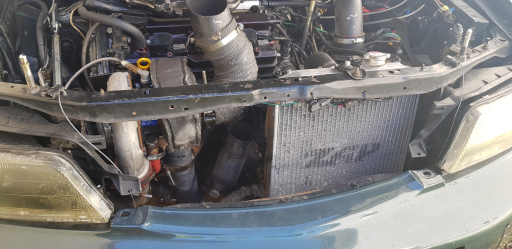
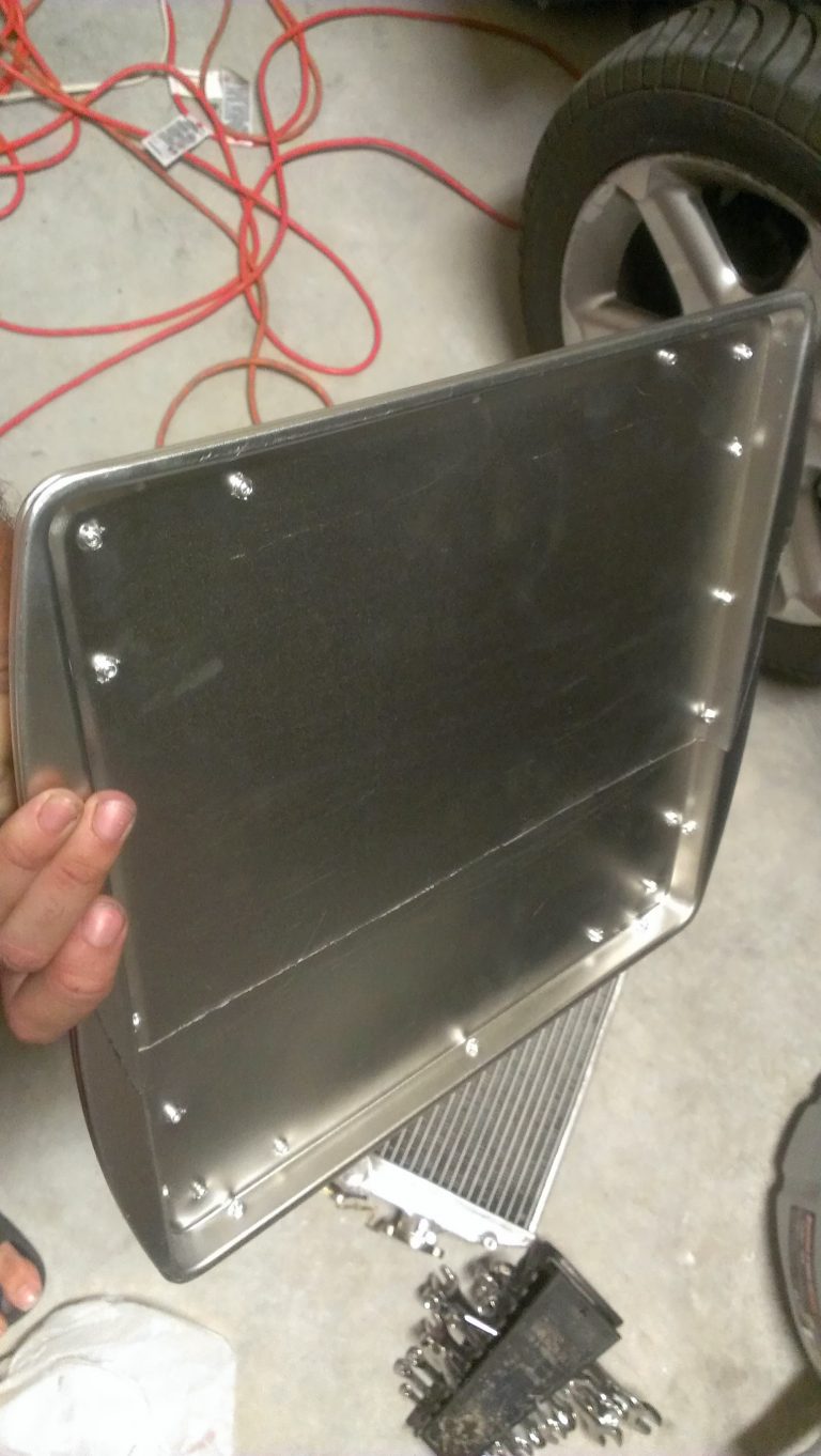
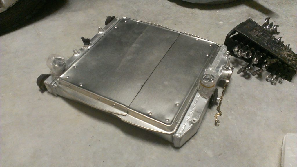
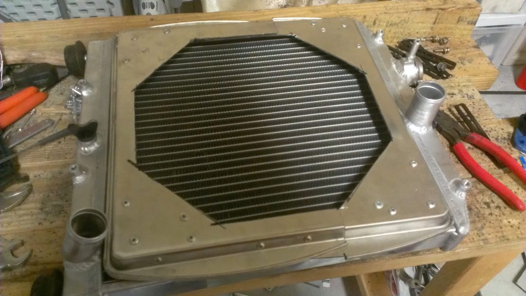
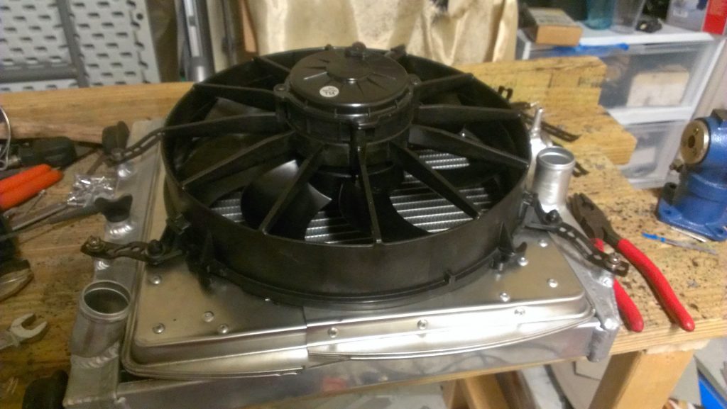
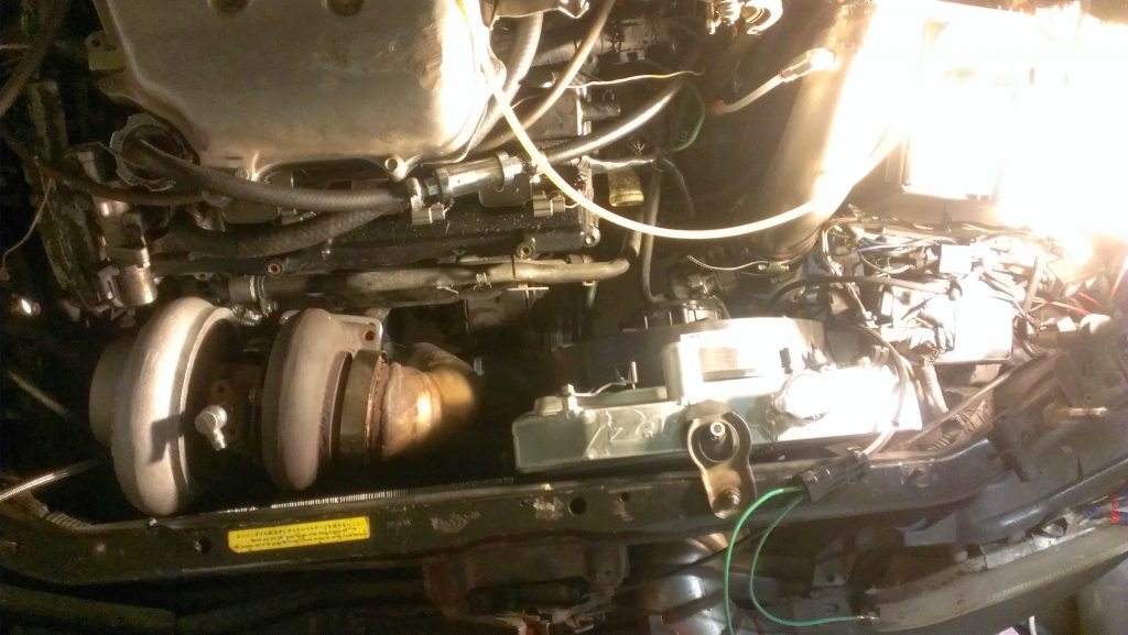
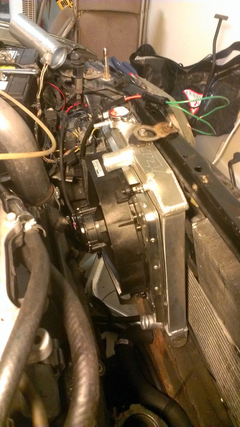
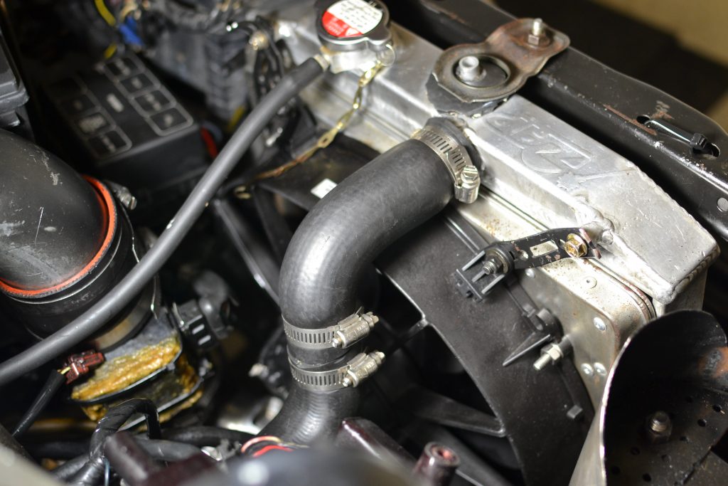
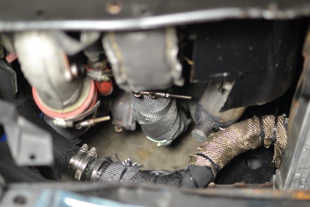
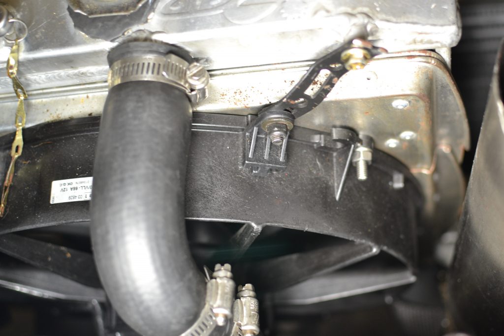
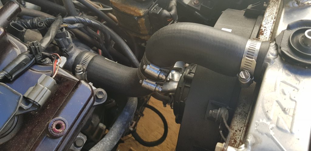
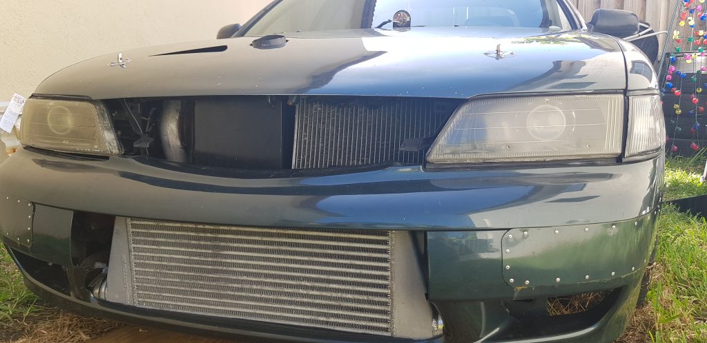
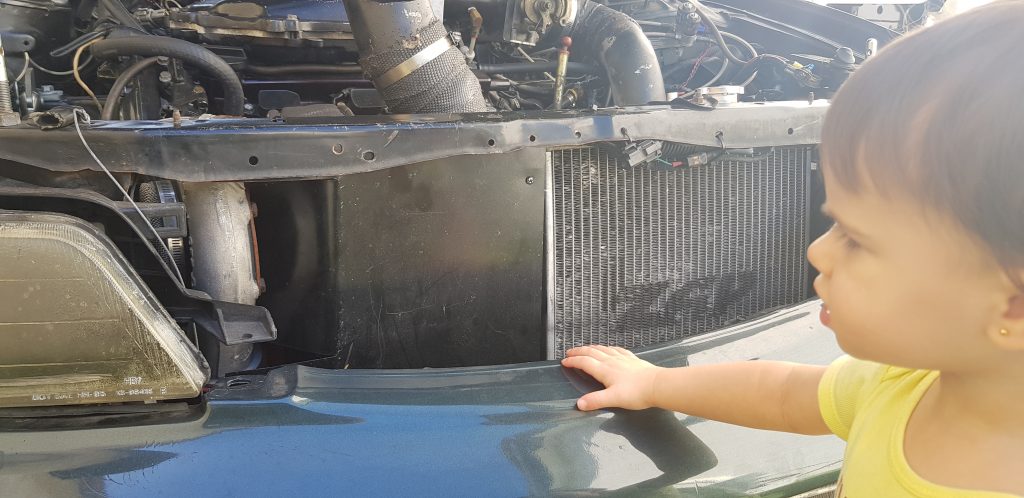
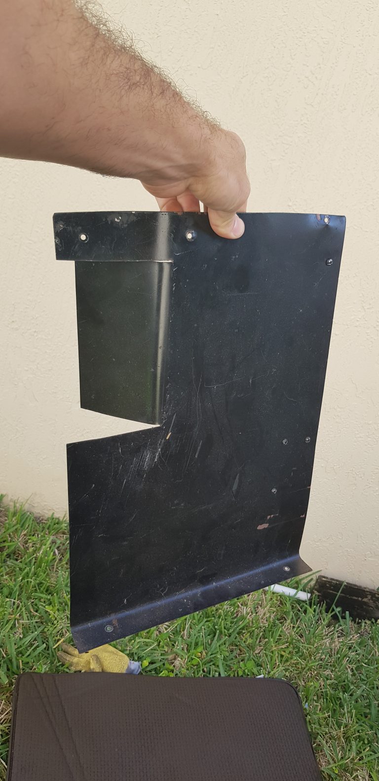
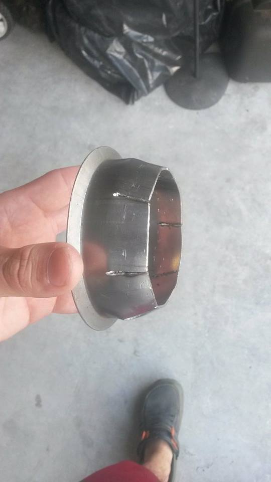
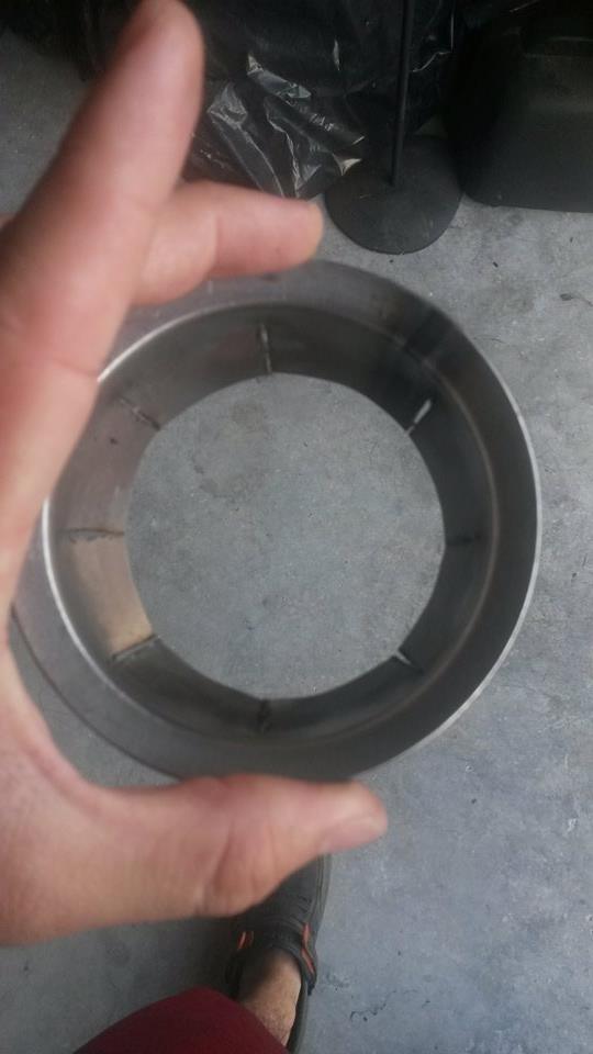
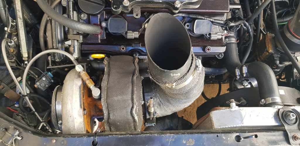
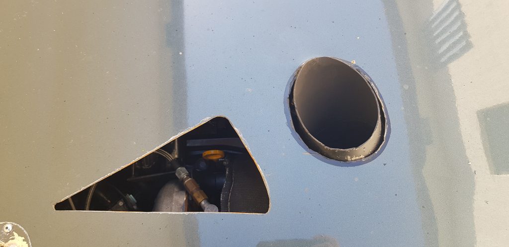
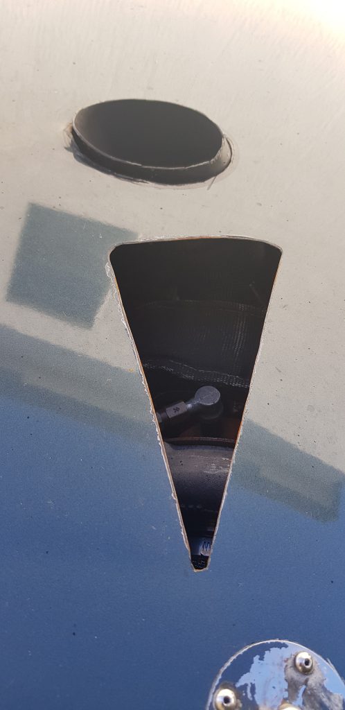
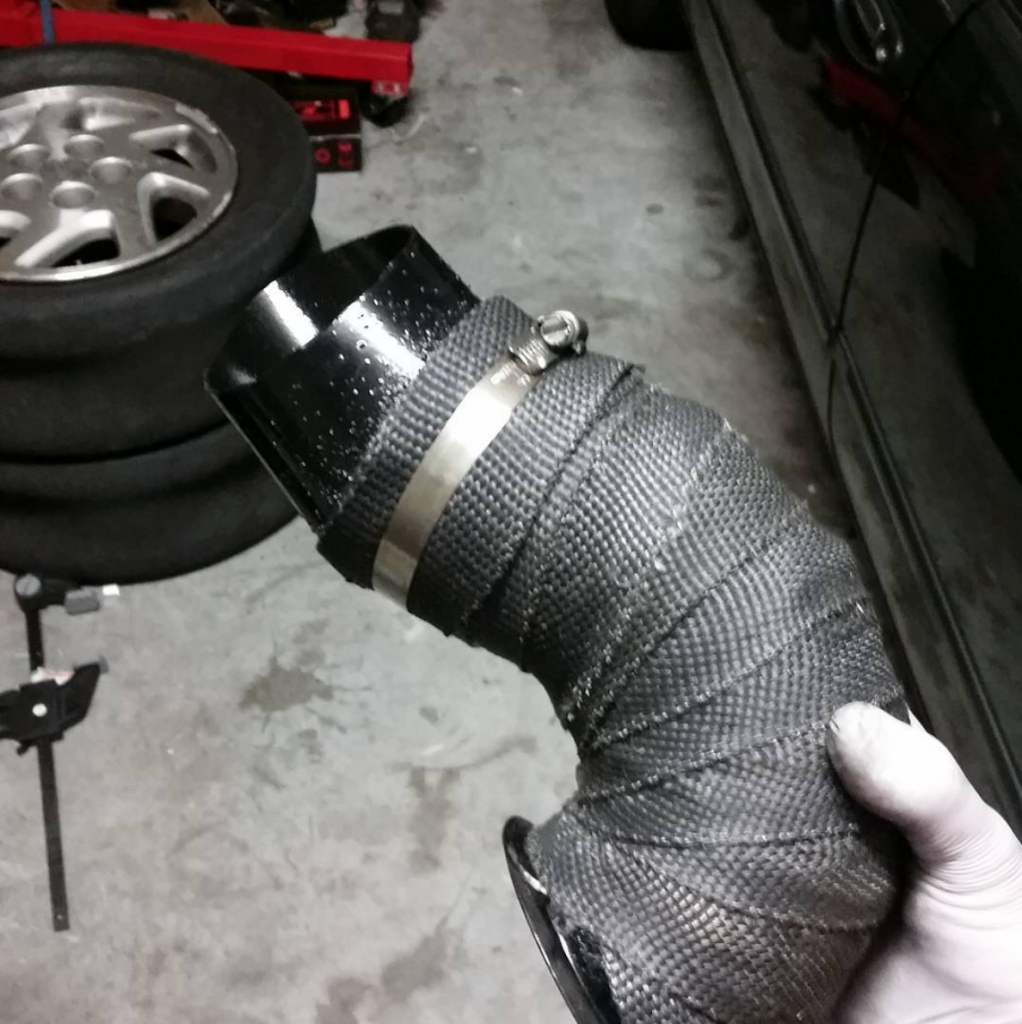


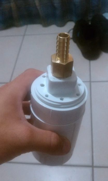
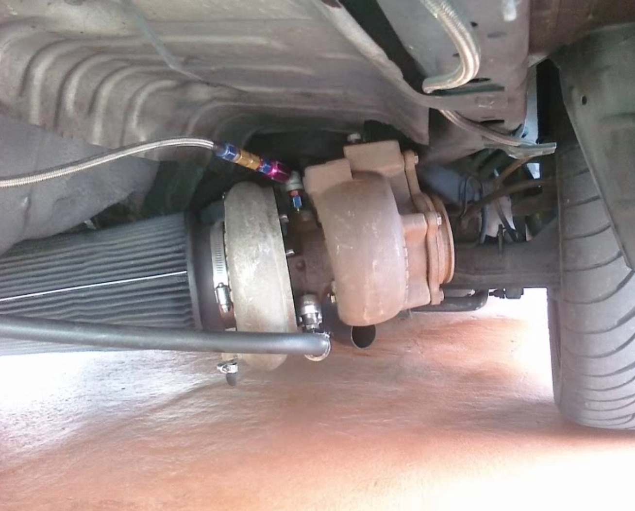
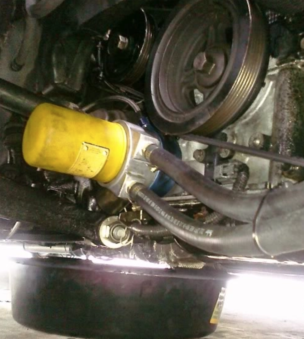
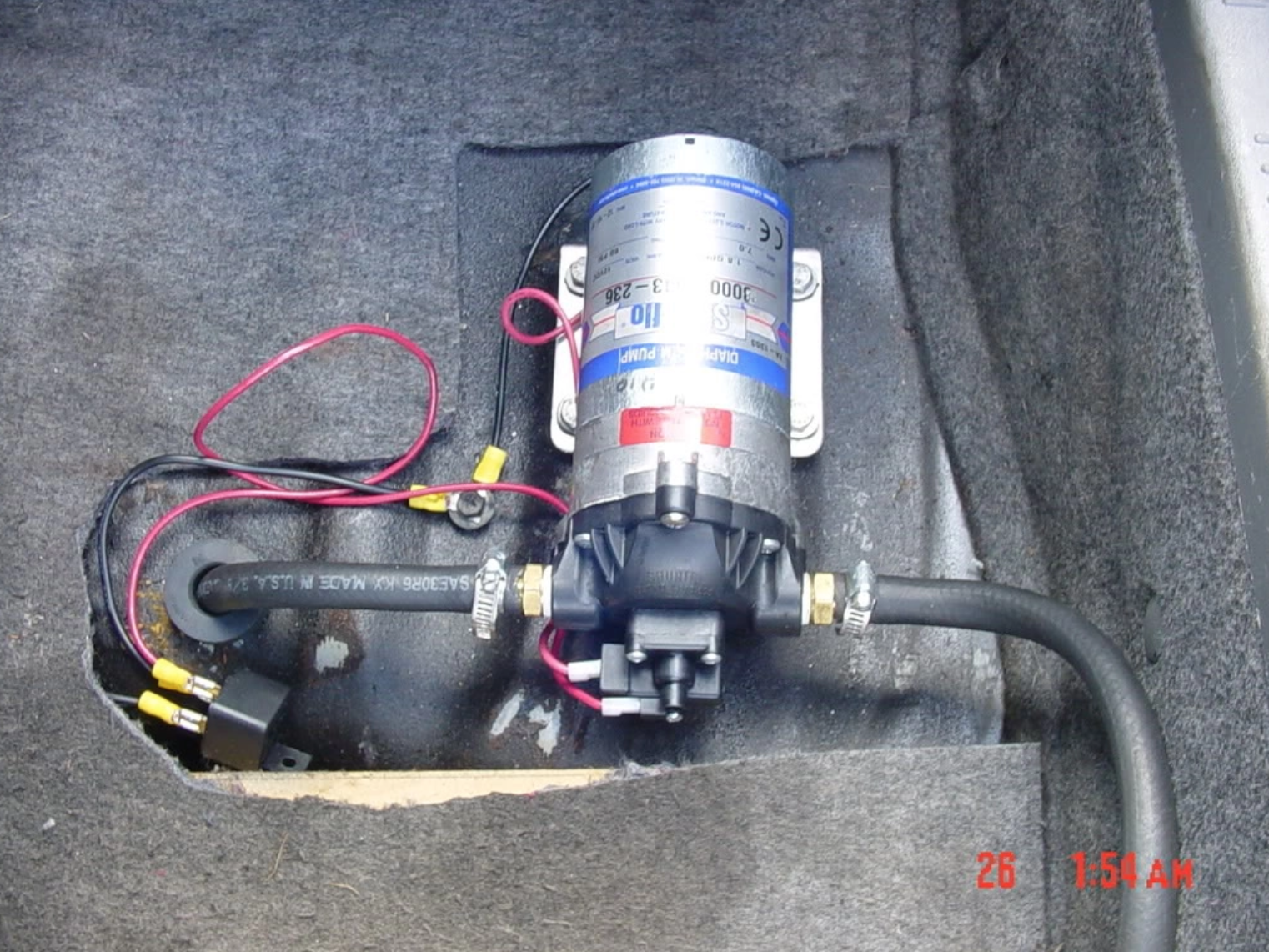
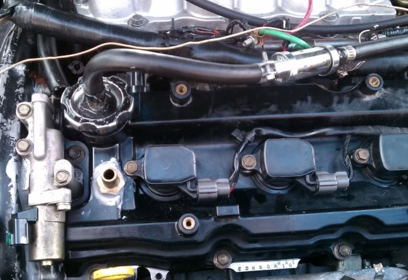
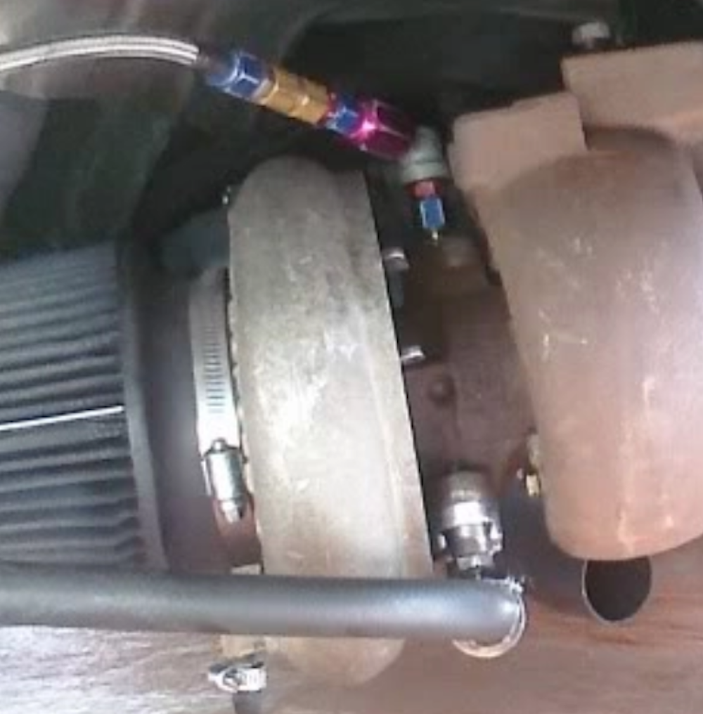
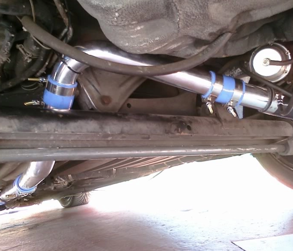
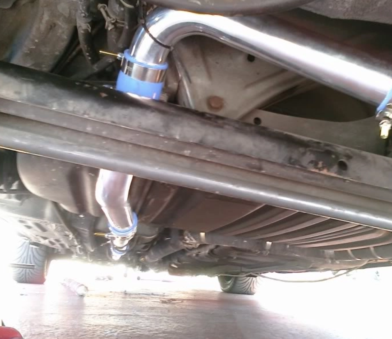
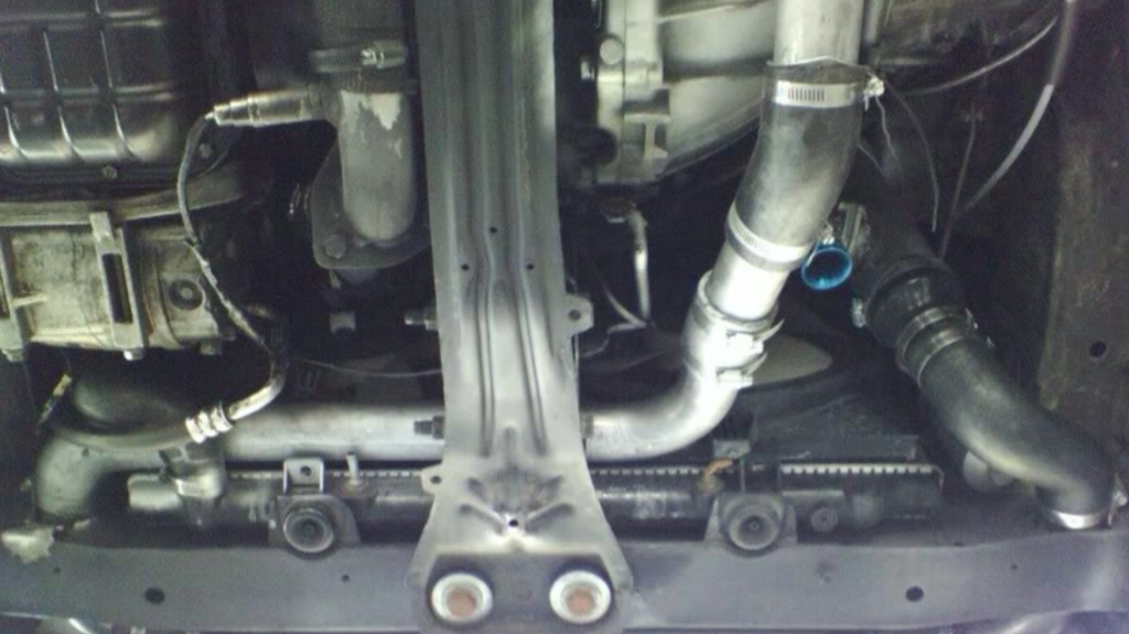
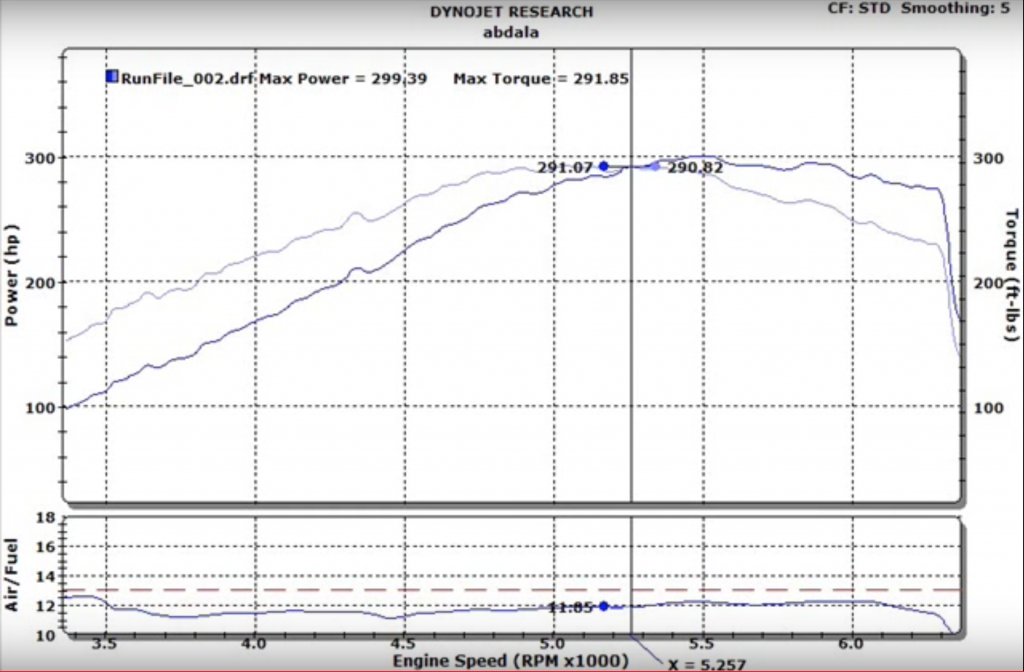
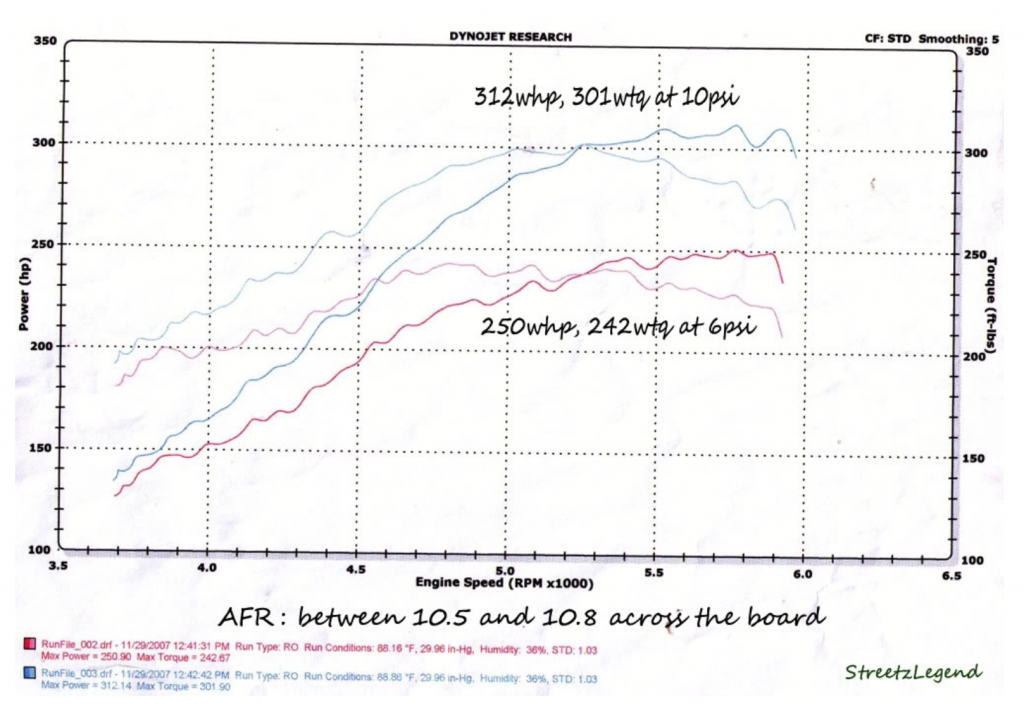
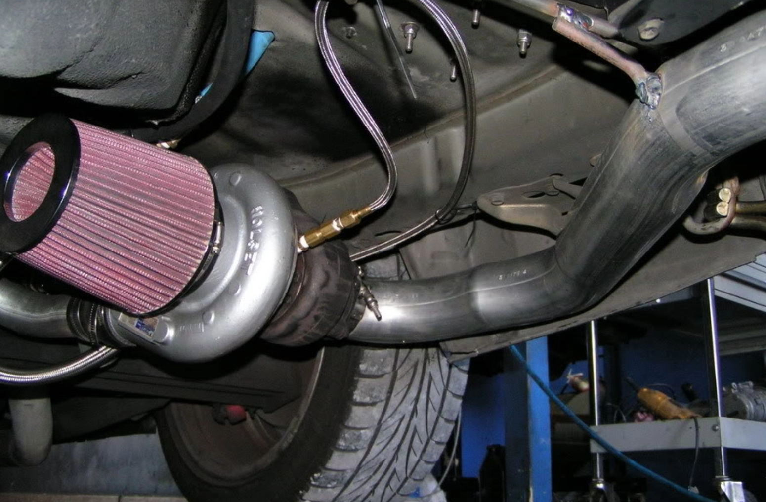
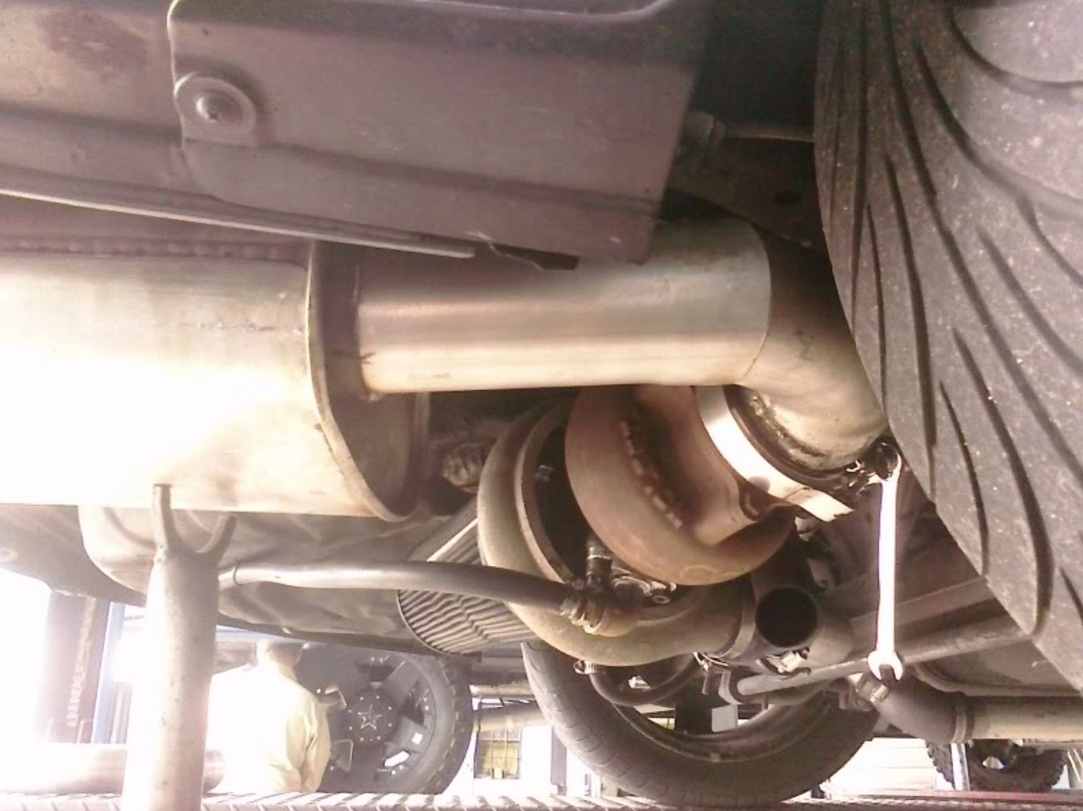
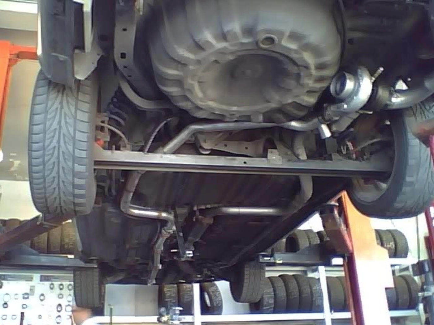
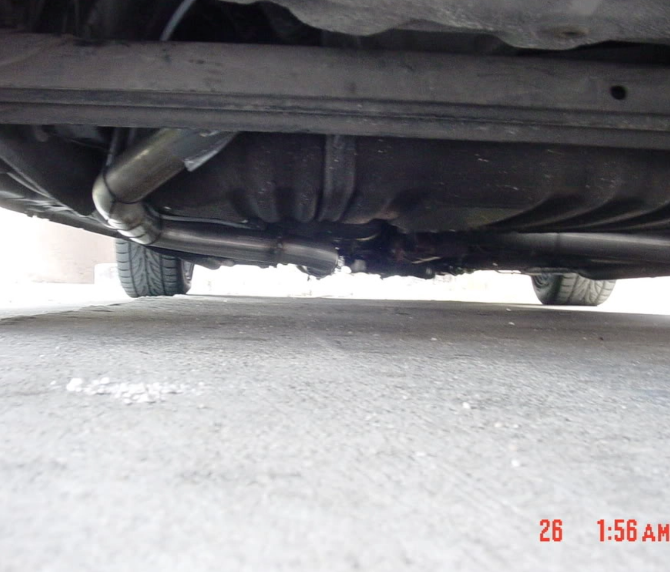
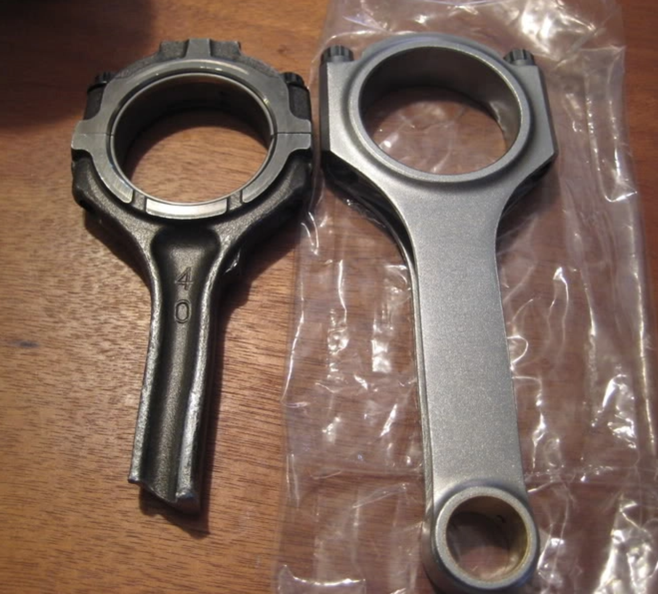
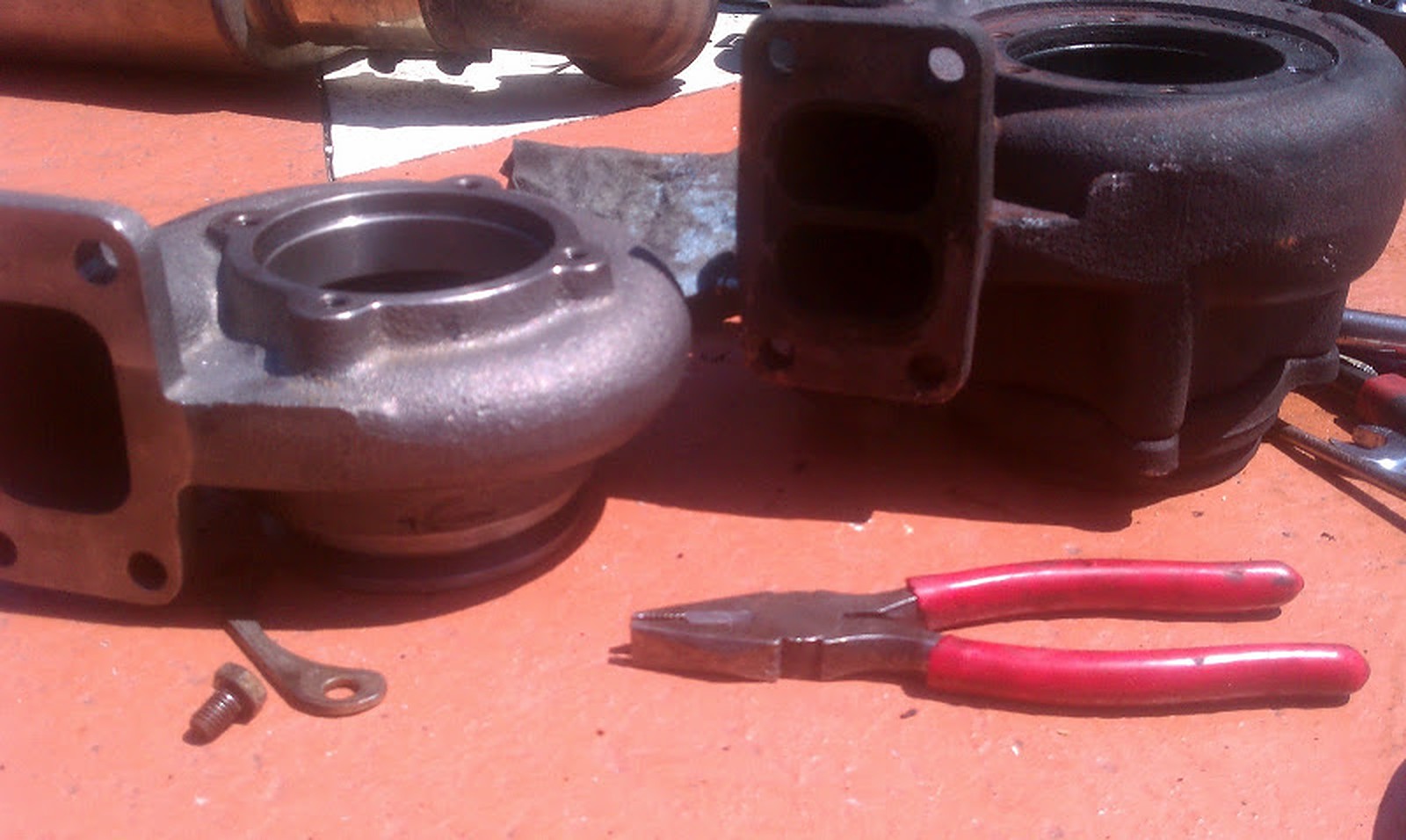
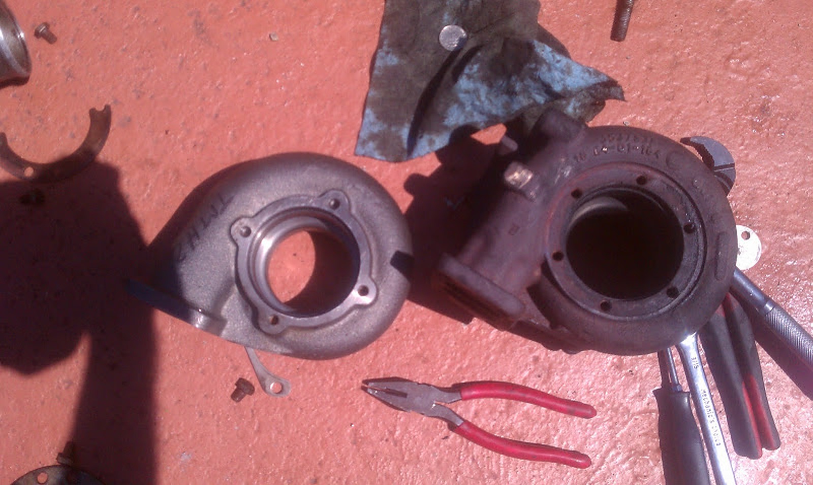
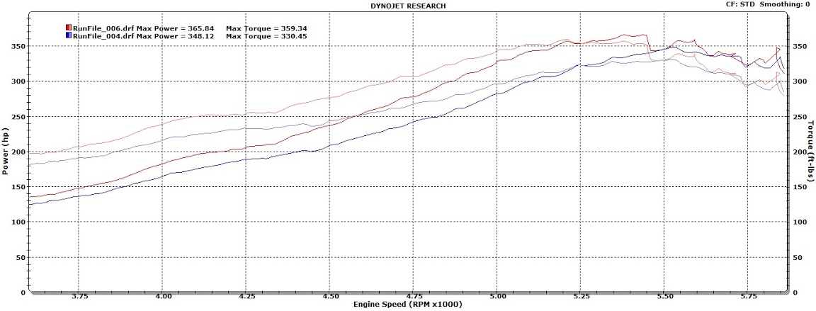

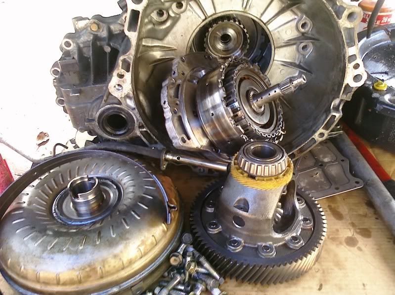
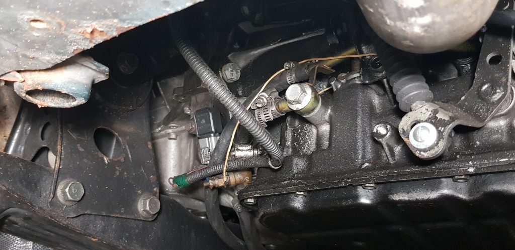
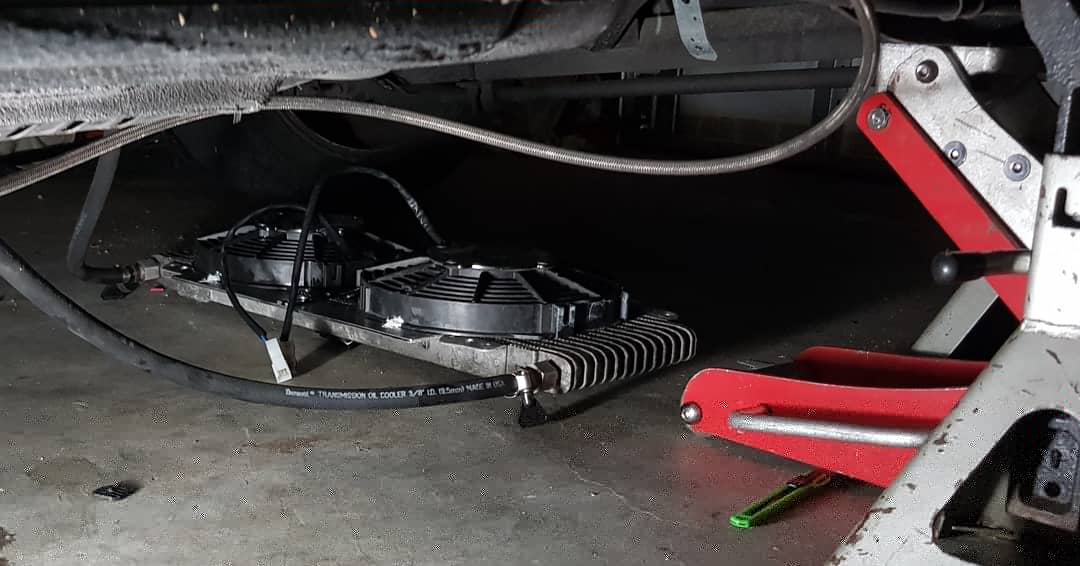


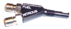
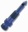
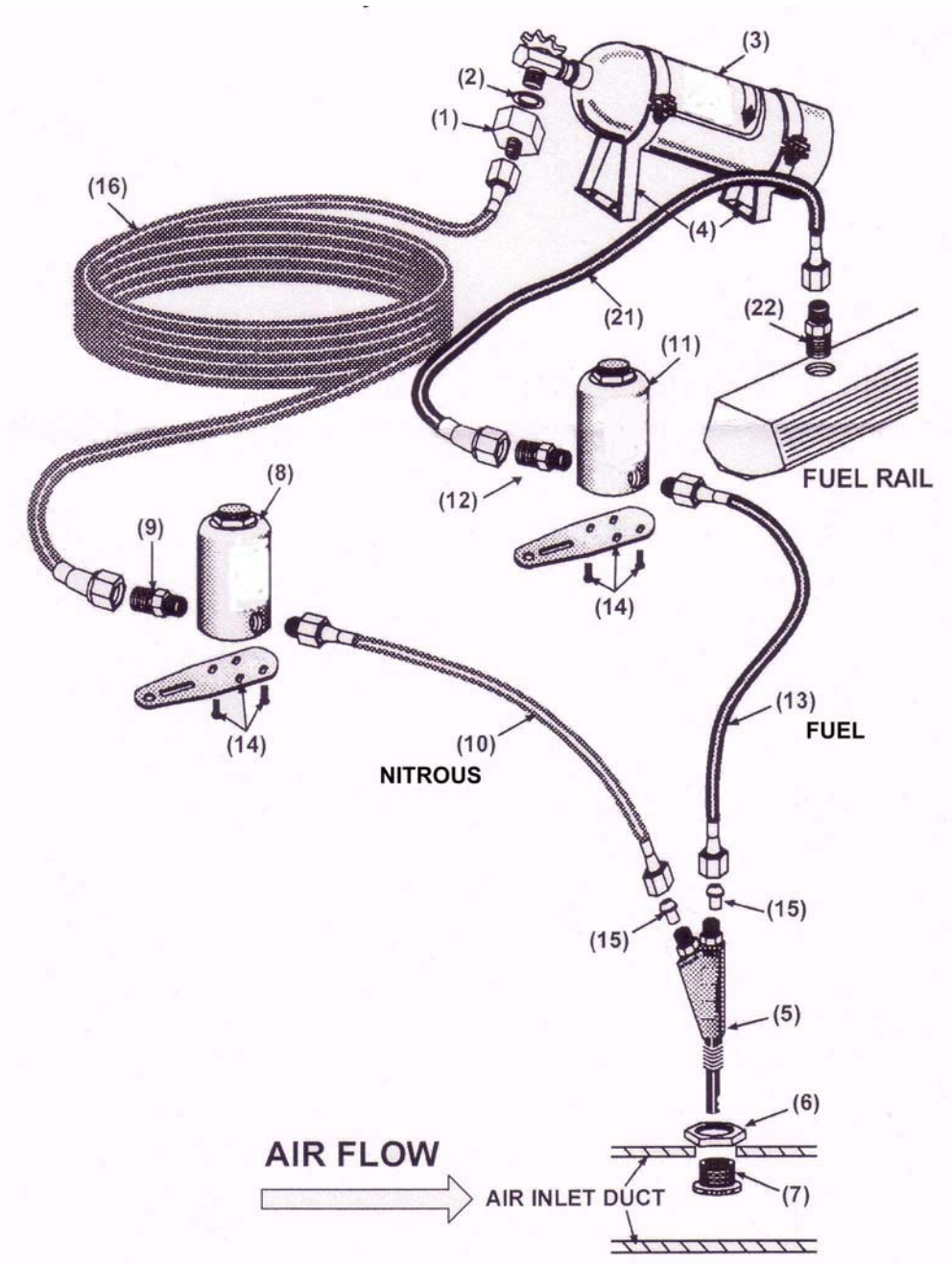
 | Info via FastMaximas.com")
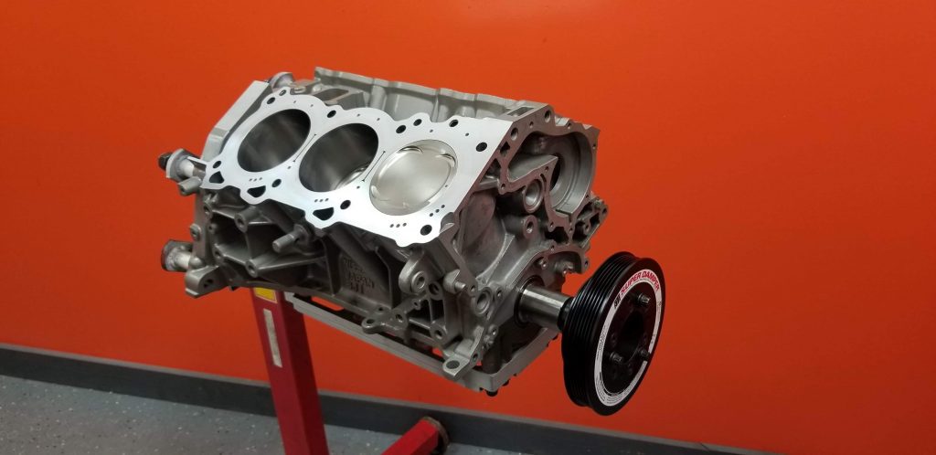
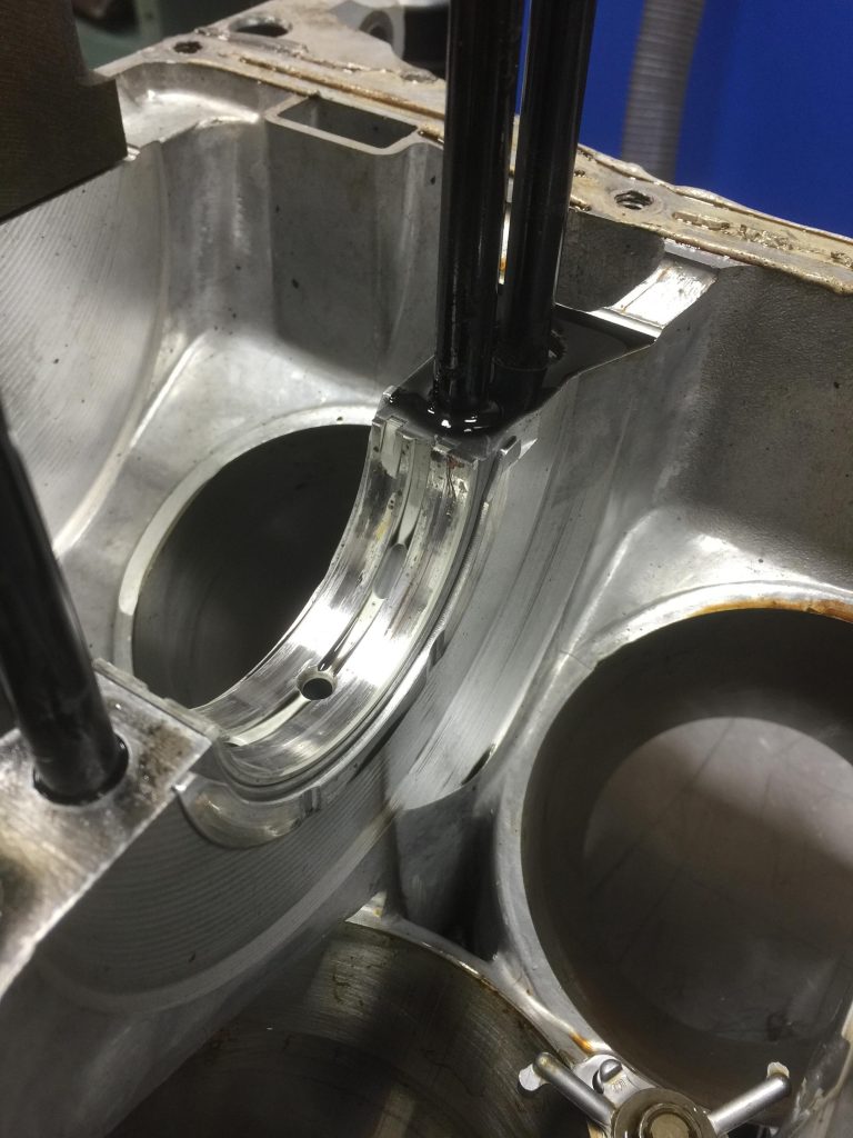
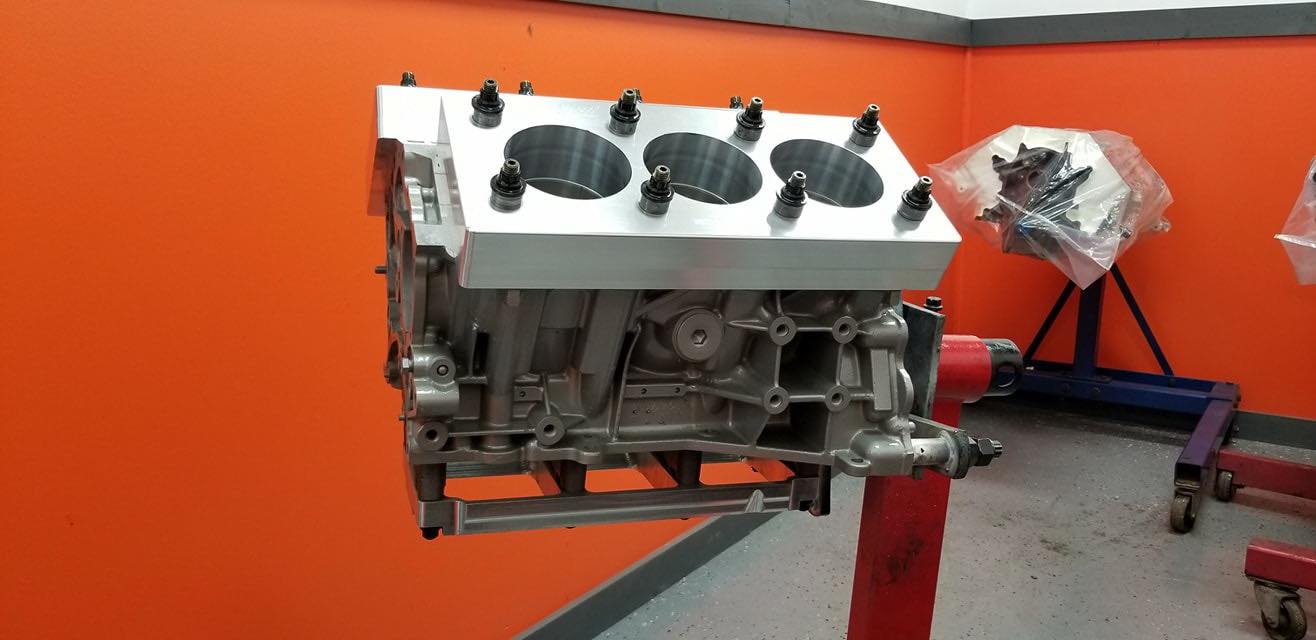
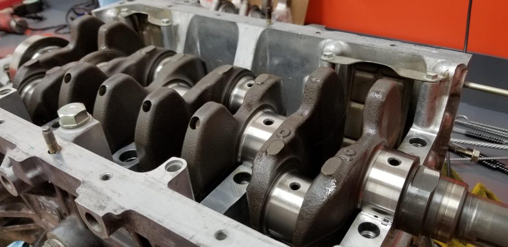


