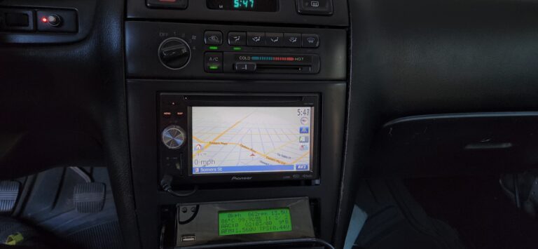
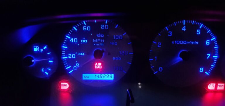
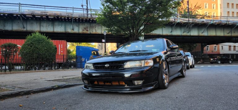
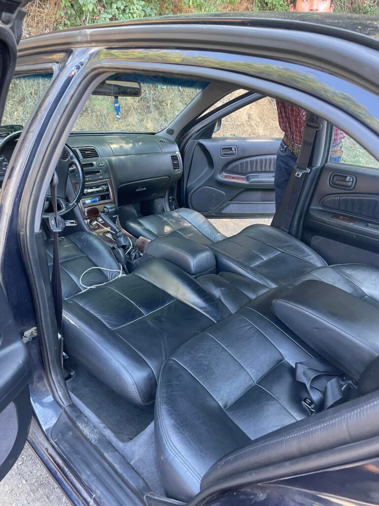
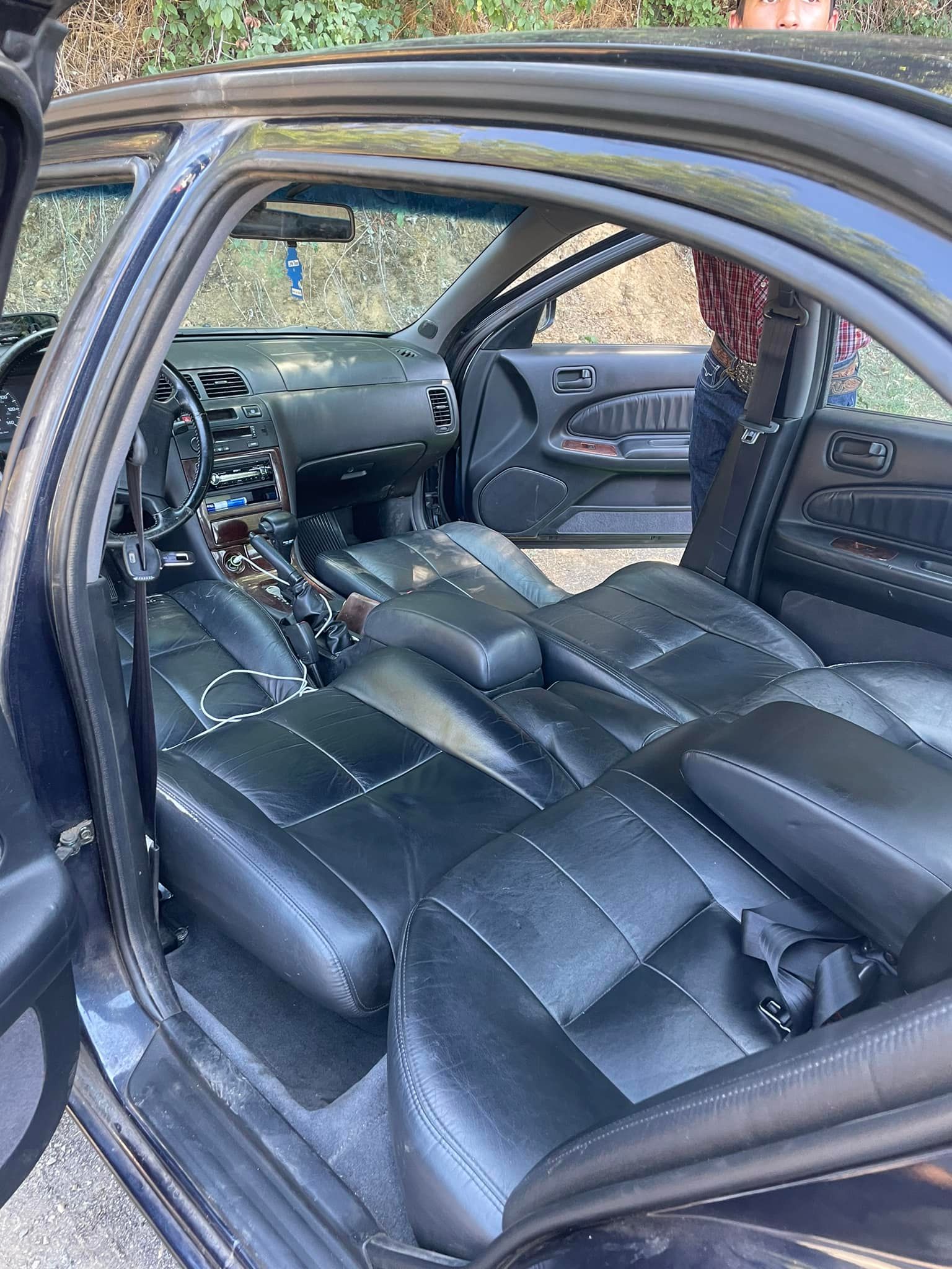
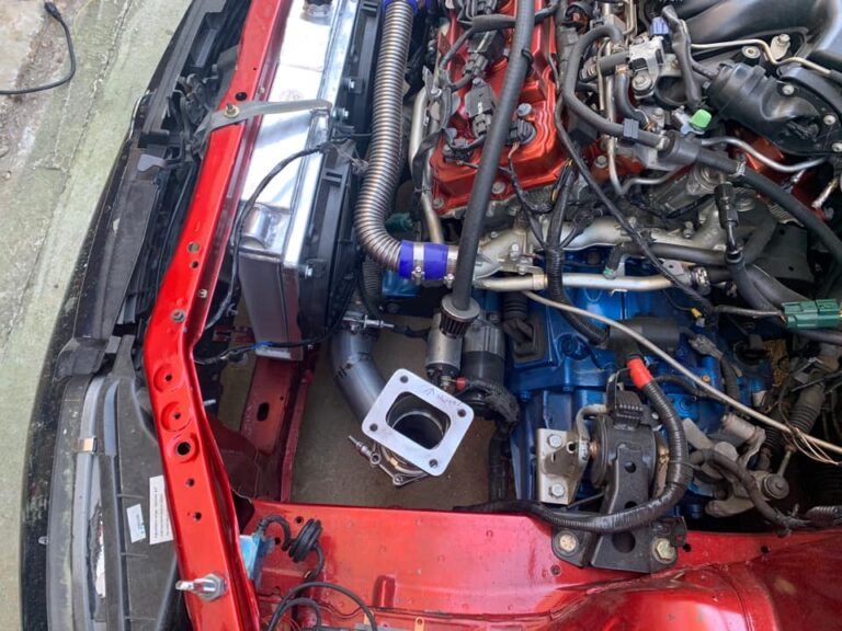
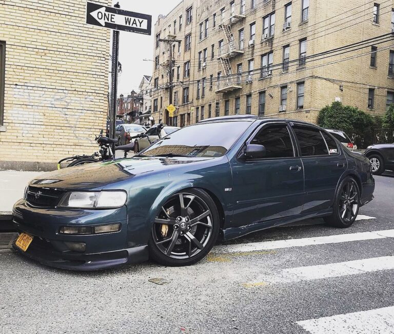
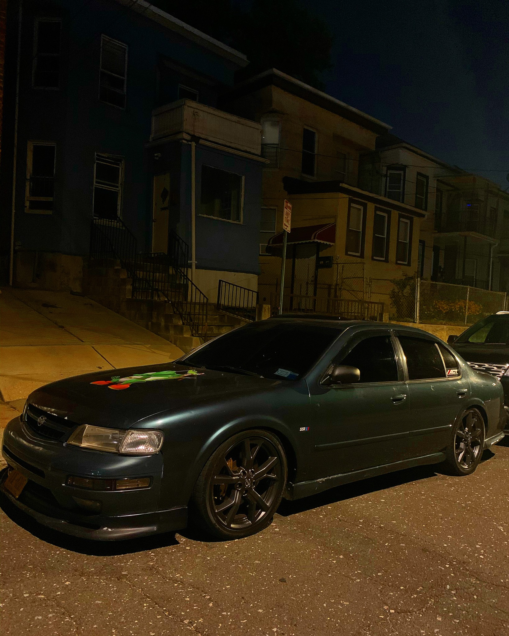
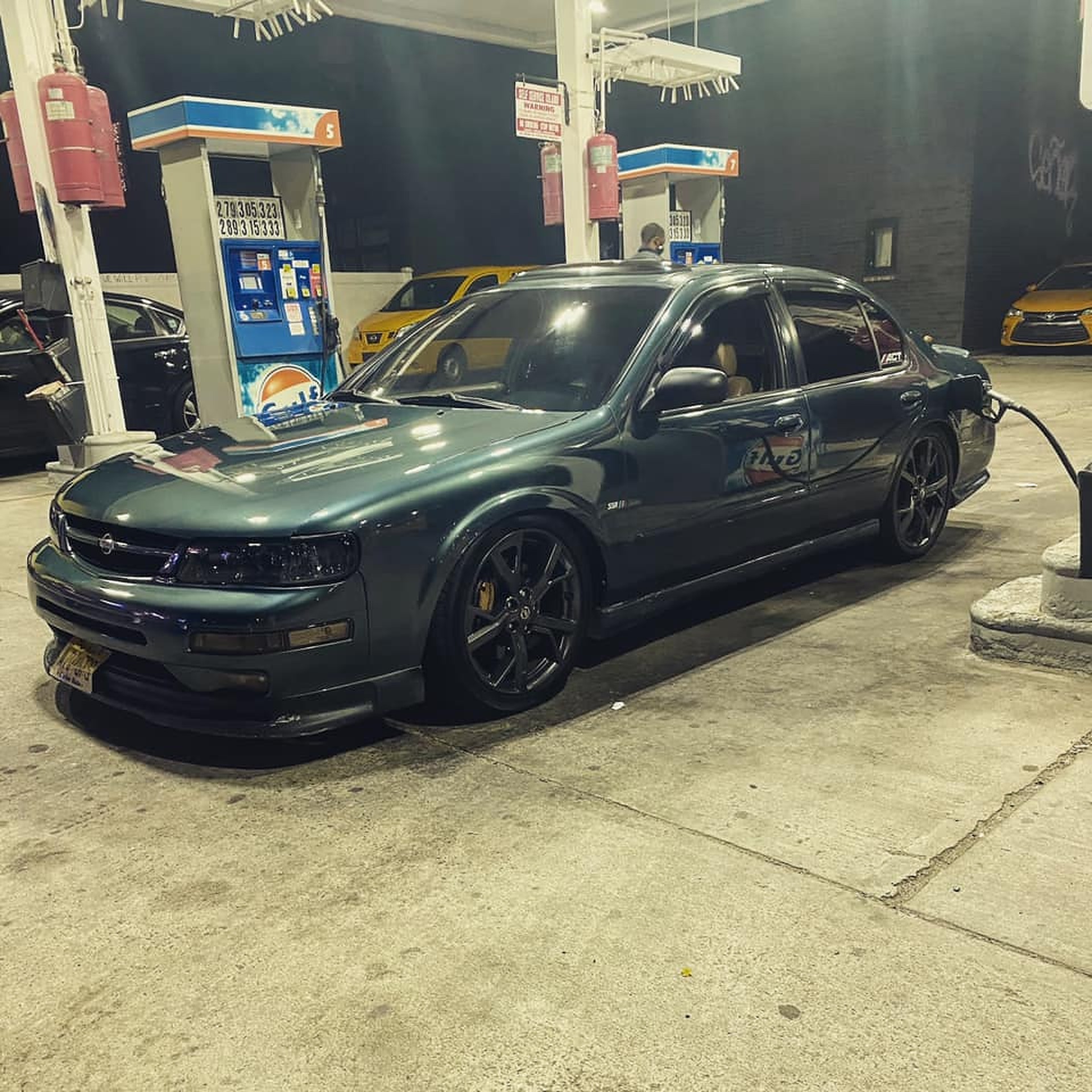
Received my ECUTalk V2 LCD from Peter and ECUTALK. It’s an awesome device and gives me all the info I need when driving my Gen3 VQ35DE supercharged 4thgen Nissan Maxima.
Features
Sensor display, showing speed, rpm, battery voltage, fuel economy (on petrol vehicles only), injector duty cycle (both banks if available), ignition timing, AAC, O2 voltage (both banks if available), water temp, AFM voltage (both banks if available), TPS voltage/%. Note: Diesel vehicles may have alternative-diesel-specific sensors displayed in place of the petrol-specific sensors: injector duty cycle, ignition timing, and AAC.
Trip meter display, showing current speed, fuel economy, and trip average speed, average fuel economy, fuel used, fuel usage rate, distance traveled, and time elapsed, for both the current trip and all trips since last cleared. Note: Fuel readings are only supported on petrol vehicles.
Fault code reading and clearing
Integrated USB consult interface pass-thru (the same as using a normal USB consult interface)
Maximum/peak sensor values recorded for the current trip
Time trials (0-60, 0-100, 0-160, 400m)
User-Definable Alerts, for Temperature, Injectors, Speed, Air Flow, RPM, and Voltage – buzzes/flashes when alert triggered
Adjustments Ability to adjust fuel/ignition timing across the board on petrol vehicles only.
Options (KPH/MPH, C/F, and TPS V/% settings, injector/cylinder setup for economy readings for petrol vehicles)
Just verified this procedure worked on my 1998 Nissan Maxima after installing a new model steering wheel and airbag.
Open the driver’s side door.
Put the key in the ignition and turn to ON (but don’t start the vehicle)
Within 7 seconds of turning the key to ON, push the driver’s side door switch button at least 5 times.
(The DOOR SWITCH is the trigger switch for interior lights located next to your door latch on the car)
The Air Bag light should go solid…give it at least 7 seconds, and it should begin to blink a 3 second, 2 second on/off pattern.
Turn ignition to OFF and remove the key.
Start the vehicle, and wait for the Air Bag light to turn off to verify that it worked.
Just successfully overhauled my a/c – report (long)
I think I’m one of the few people that have done this, so I’ll post my findings here. In short, a/c repair IS possible if you do some research, take a little care with O-ring connections and buy a set of pressure gauges. I saved myself 600 dollars and I now have a set of gauges and a vacuum pump for any work on future cars. If you can rent a vacuum pump or get a garage to do the vacuum/recharge you can save more in the short term.
Here’s how I got my ice-cold air back
1. Bought a set of gauges and did some research at aircondition.com and ackits.com. These are excellent boards with a/c service professionals making daily contributions. The gauges I bought from the tool warehouse.
2. Found that my low side pressure was too high and my high side pressure was too low. Diagnosis: shot compressor. This was fairly easy because it was starting to make noise and get worse with time.
3. Unfortunately a dead compressor can spew metal parts around other components (black death). In my case I couldn’t just replace the compressor because that crud can cycle around to the new compressor and kill it very quickly. Our condensers are parallel flow condensers, so flushing often fails. I decided to replace it.
4. At this point I had a choice to make – get an a/c shop to vacuum and recharge my system or buy a vacuum pump. They can apparently be rented too but I couldn’t find any in my area. I figured why not pick one up, it’ll serve me well for years. Got some vacuum pump oil and a pump from the tool warehouse.
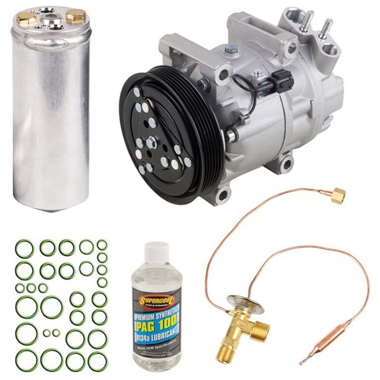
5. As an expansion valve is only 45 bucks, I picked up one of those too. O-rings are important to prevent leaks, and should be replaced whenever a system is opened up. My shopping list was now:
compressor, dryer, expansion valve (all from Carlisle Auto Air).
condenser, o-rings, compressor oil, nylog (an excellent o-ring conditioner that minimises leaks) and flush solvent (all from ackits.com).
6. The whole job took about 10 hours, but it’s pretty straightforward.
a) Add six ounces of oil to the compressor and 2.5 to the dryer (do the dryer bit right at the end).
b) Undo the drivebelt and bolt on the new compressor.
c) Drain coolant, remove radiator and install condenser.
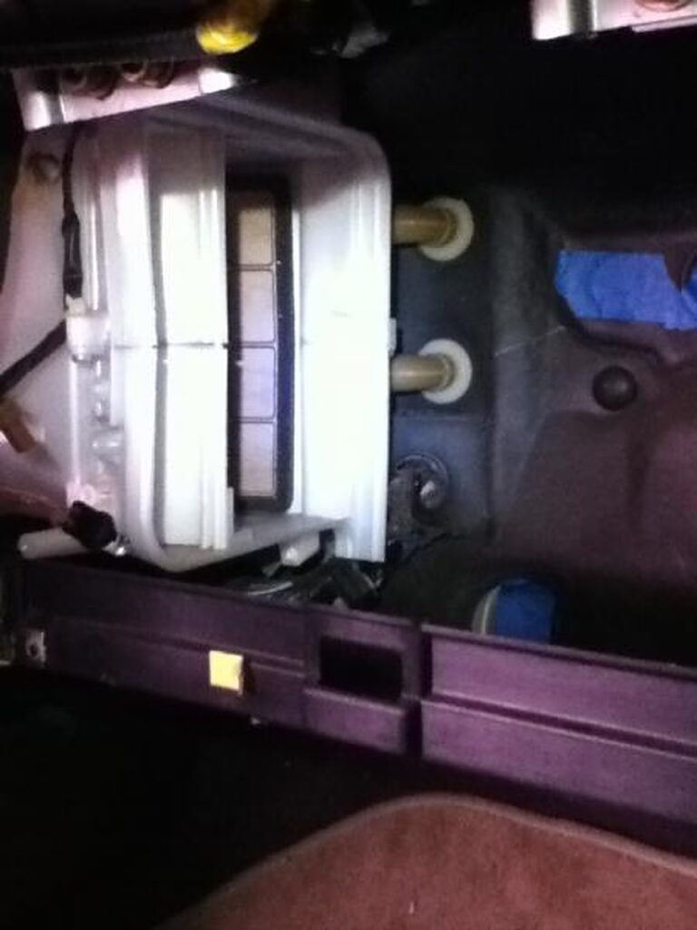
d) Expansion valve was the trickiest – remove glove box (six screws), unbolt refrigerant lines near the firewall (two bolts), remove evaporator housing (four screws), open up evaporator case (six screws), remove old expansion valve (three bolts and a bit of tape). At this point I added flush solvent to the evaporator and blew some compressed air through it. Then I replaced the expansion valve.
d) Replace dryer last it’s good to keep it sealed until it’s needed so that the dessicant bag doesn’t get saturated with moisture).
7. When each pipe between components was unhooked at both ends, I poured in some flush solvent and blew compressed air through to clean them out. One of the tubes is long and most of the others are pretty short so it wasn’t much of a big deal. O-rings were replaced and covered in a thin layer of nylog as I went along.
8. Vacuumed system down for an hour, added a bit of refrigerant and watched the pressure gauges for 20 minutes. No leaks, so continued to fill until almost two cans of 12 oz refrigerant (1.4 lbs) had been added. Air was cold, job done!
This probably looks long, and in some ways it is. But some of you guys do much more complicated stuff than this. One thing I don’t like is being told by mechanics to never touch my a/c because it’s “complicated” or “beyond the DIYer”. The truth is it’s a pump, valve, two heat exchangers and a dryer, and no-one should be scared about doing work on it. I would say if you’re serious about it, buy a set of gauges for 60 bucks. If you don’t want to buy the gauges, then it’s probably not for you.
The old saying of “Do it right, do it once” definitely applies, but providing you do some research and don’t cut corners you’ll be fine and can save a lot of money.
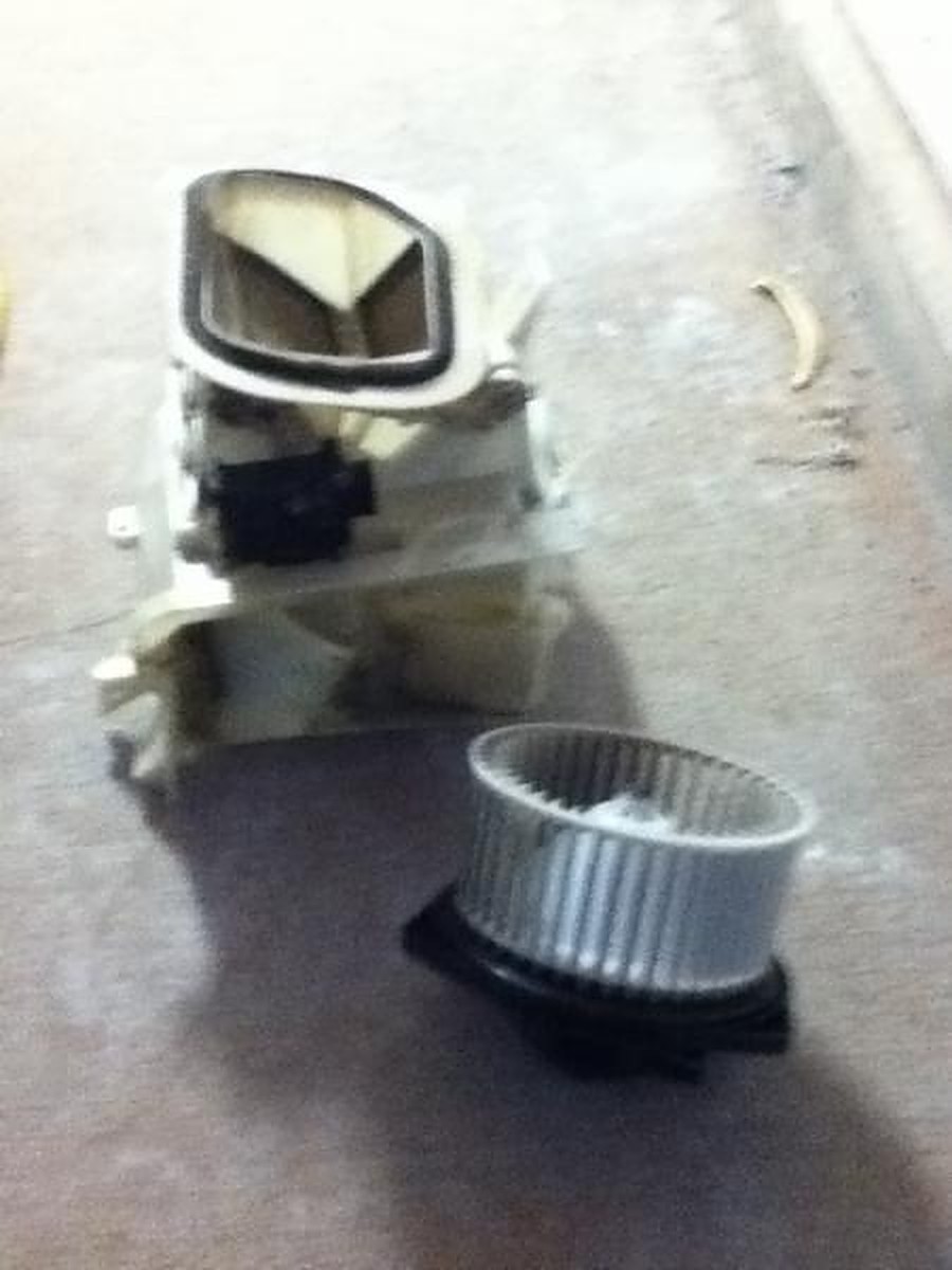
Remove ac blower/fan first (it’s the white one to the right of the black box (a/c expansion chamber) then remove expansion chamber.
Be sure to remove all screws holding the “black box” (a/c expansion chamber/valve housing) first! don’t muscle your way and pry it open with brute force!
When putting everything back in, remember to completely reassemble the “black box” (a/c chamber housing) first then put everything back in.
This is time consuming, and removing/replacing the a/c chamber housing is a b*tch, practically no room to take that thing out.
The mixture ratio feedback control system monitors the mixture ratio signal transmitted from air fuel ratio (A/F) sensor 1. This feedback signal is then sent to the Engine Control Module (ECM). The ECM controls the basic mixture ratio as close to the theoretical mixture ratio as possible. However, the basic mixture ratio is not necessarily controlled as originally designed. Both manufacturing differences (i.e., mass air flow sensor hot wire) and characteristic changes during operation (i.e., fuel injector clogging) directly affect mixture ratio.
Accordingly, the difference between the basic and theoretical mixture ratios is monitored in this system. This is then computed in terms of “injection pulse duration” to automatically compensate for the difference between the two ratios.
“Fuel trim” refers to the feedback compensation value compared against the basic injection duration. Fuel trim includes short term fuel trim and long term fuel trim.
“Short term fuel trim” is the short-term fuel compensation used to maintain the mixture ratio at its theoretical value. The signal from air fuel ratio (A/F) sensor 1 indicates whether the mixture ratio is RICH or LEAN compared to the theoretical value. The signal then triggers a reduction in fuel volume if the mixture ratio is rich, and an increase in fuel volume if it is lean.
“Long term fuel trim” is overall fuel compensation carried out long-term to compensate for continual deviation of the short term fuel trim from the central value. Such deviation will occur due to individual engine differences, wear over time and changes in the usage environment.
Instructions
Start engine and warm it up to normal operating temperature.
Turn ignition switch OFF.
Disconnect mass air flow sensor harness connector, and restart and run engine for at least 3 seconds at idle speed.
Stop engine and reconnect mass air flow sensor harness connector.
Make sure Detected Trouble Code (DTC) P0102 is displayed.
Erase the DTC memory. (This could be done by disconnecting the car battery for 30-45 min or with a scanner)
This may be common knowledge but I did not see it in the stickies. There are three basic steps involved:
1) On the ECU connector, move the wire from pin 107 to pin 105.
2) Change out your 4-wire zirconia type rear O2 sensor for a 3-wire titania type.
3) Also must add rear O2 sensor signal ground from ecu pin 112 to engine grounds F18 and F19 on intake manifold collector.
Please be aware that you cannot sub a 3-wire zirconia type sensor in place of the 3-wire titania. The two types work completely differently. The zirconia type generates a voltage depending upon O2 levels. The ECU expects to see a fluctuating voltage from 0-1.0 V.
The titania type sensor changes in resistance depending on O2 levels. The ECU measures the voltage drop across this resistance. It expects a voltage fluctuating between 0-2.2V. If the ECU does not see the specified voltage fluctuation after a given time period, it will throw the P0136 code and give you a CEL.
Some of you may have discovered that the rear O2 sensor bung on a 98 is an 18mm thread while the one on a 96 is 12mm.
There are three options for sensor replacement:
Buy a 12mm, 3-wire titania type for a 96 and machine an adapter for it to fit the 18mm threaded bung.
Weld a 12 mm bung on your exhaust and use the 96 sensor.
Buy an 18mm, 3-wire titania type sensor. Easier said than done. Not used on any North American production cars that I am aware of. NTK Europe makes them but NTK North America does not. All of the 3 wire titania ones over here are 12mm.
I believe I found one through Oxygensensors.com. It is Walker p/n: 250-23881. It is a universal type, so you will have to cut the connector off of your factory sensor.
I know someone is going to ask the question: Will this work on a 99???
Short answer: I do not know. Long Answer: I know the 99 uses a four-wire 18 mm zirconia type like the 98. The nissan p/ns may be different but that just means the connector or length of wire attached to the sensor is different. You would be replacing it with a universal so that does not matter.
I have FSMs for 96 and 98, not 99. The pin-out on the ECU may be different. If someone wants to supply me with the schematic for the rear O2 sensor circuit, I can let you know.
I apologize for the long post, but since there is a GD for JWT ecus going on right now, I figured this would be useful info for some of us 98s.
*********UPDATE*********
New O2 sensor finally arrived on Friday – installed it Sunday night
Problem – I am not picking up any voltage output from it on my OBD2 scanner.
A quick check of the 96 ECU schematic reveals the problem. The ECU requires a separate signal ground for the rear O2 sensor to be on pin 112.
Damn 3 wire sensors – the four wire types have a built in signal ground so no separate wire is necessary.
Time to hit the wrecking yard again. Probably the best place to get some of those “fancy” female terminals that go inside the ECU harness connector.
*********UPDATE*********
CODE P1220 GONE AS WELL
CODE FREE AND READY FOR EMISSIONS TESTING
Wired the FPCM and dropping resistor in on Saturday. Had to tun two new wires from the ECU to the left rear quarter where the modules are located. Some minor re-wiring of the body grounds and fuel pump were also required.
For all you 98s, this step should only be necessary if you have a 95/96 ECU out of a cali-spec or Canadian maxima and are getting the P1220 code.
Spare ’96 ecu will arrive at Technosquare today.
For any of you 98 cali-spec owners looking to convert to a 95/96 ecu, I have a whole harness full of ecu pins available. I can pop a couple in an envelope with ~24″ of wire attached and mail them out.
*********UPDATE*********
Just an update that may save some people some money.
Before going out and buying the titania 02 sensor:
1) On the ECU connector, move the wire from pin 107 to pin 105. There should be no existing wire in 105.
2) Ground ecu pin 112 (this is the rear 02 sensor ground)
I believe Dandymax just carried out the above two steps and it got rid of the P0136 for him. If it doesn’t work for you, then you will have to buy the sensor.