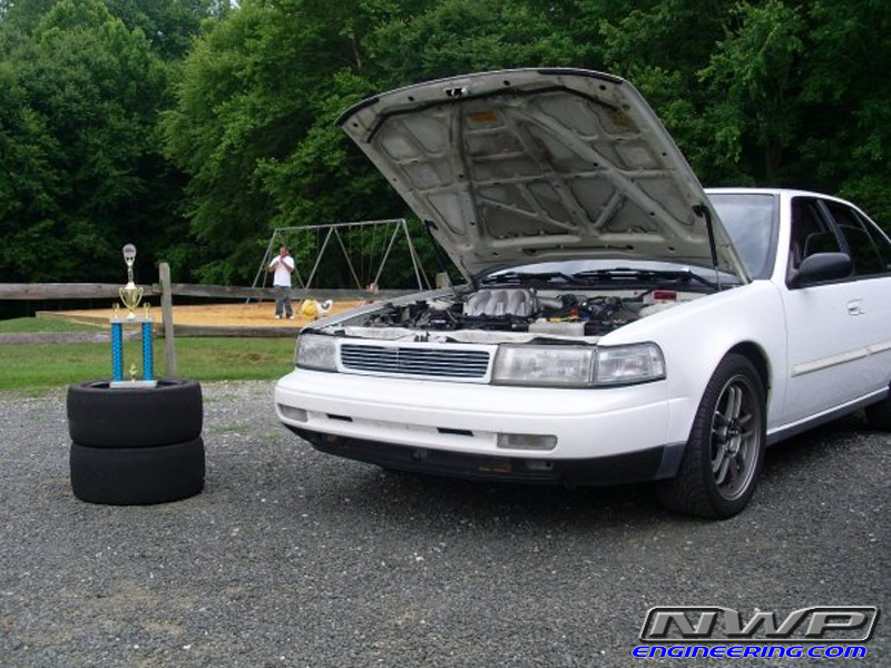
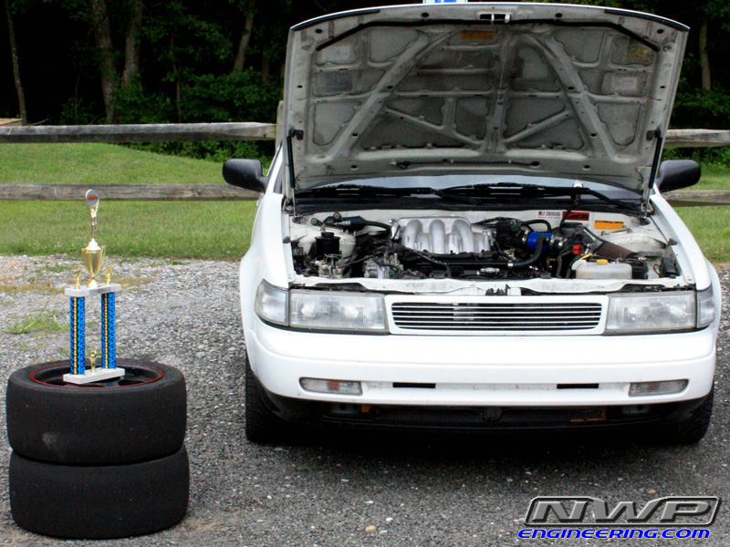
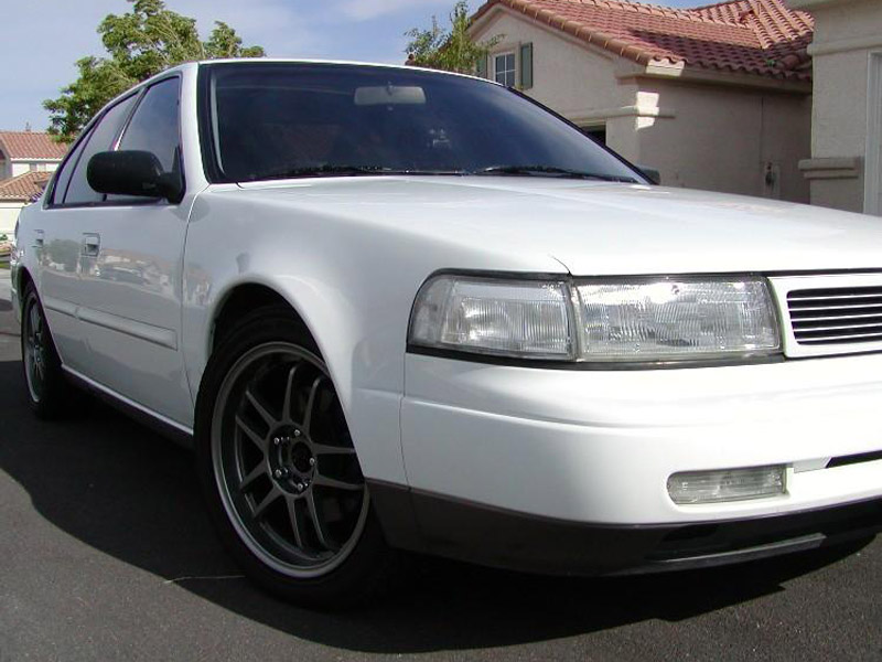
Year: 1992 Model: Maxima Color: White Trim: SE Engine: VQ35DE Transmission: 4-Speed Automatic Transmission
Highlights:
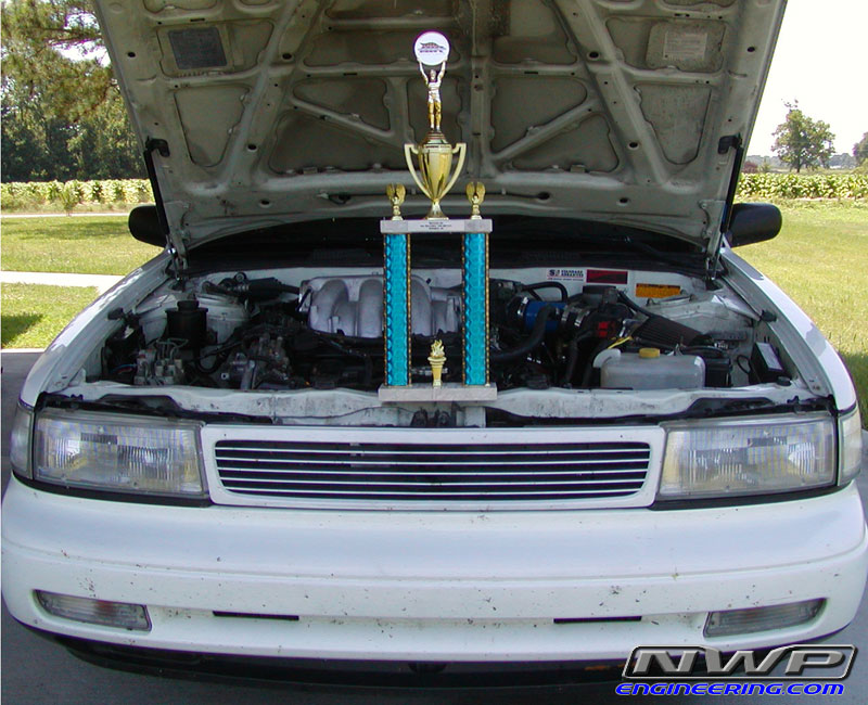
This is the first known FULL 2002 ECU 3.5L swap into a 3rd gen Maxima.
On Sunday, February 16th, 2014, it ran an 11.97 @ 113.3mph in the 1/4 mile NATURALLY ASPIRATED! Took place at at Coastal Plains Dragway in Jacksonville, NC.
First Maxima to do 11s in the 1/4 mile All Motor.
Horsepower: 335HP at crank and 300 WHP ALL MOTOR
Curb Weight at track (with driver): 2600 lbs
Mod List:
Quick Car Info
1992 Nissan Maxima SE w/ 3.5L Engine
Original Automatic Transmission w/ 215K+ miles (RE4F04V)
Engine from 02 Maxima w/ 49K miles
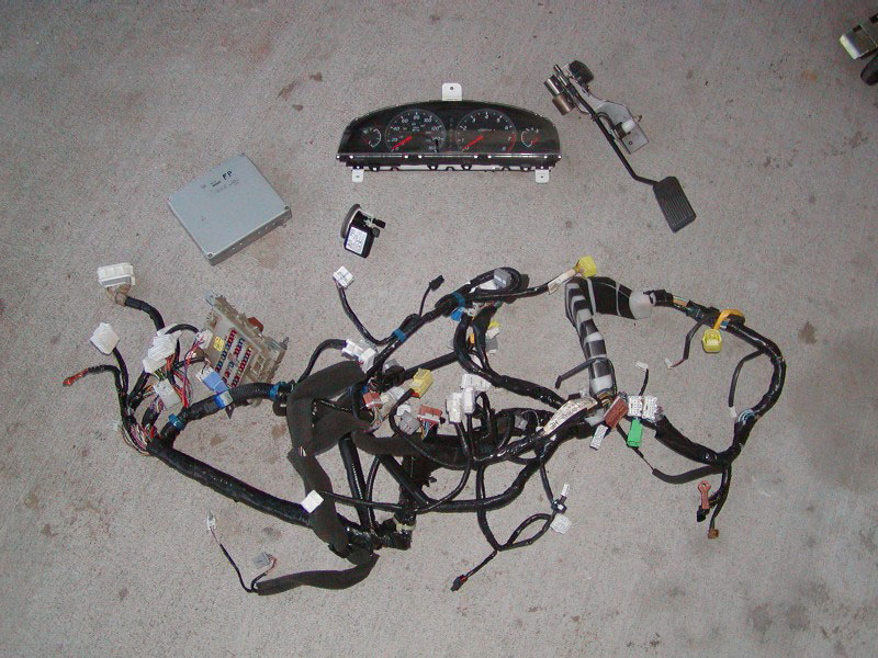
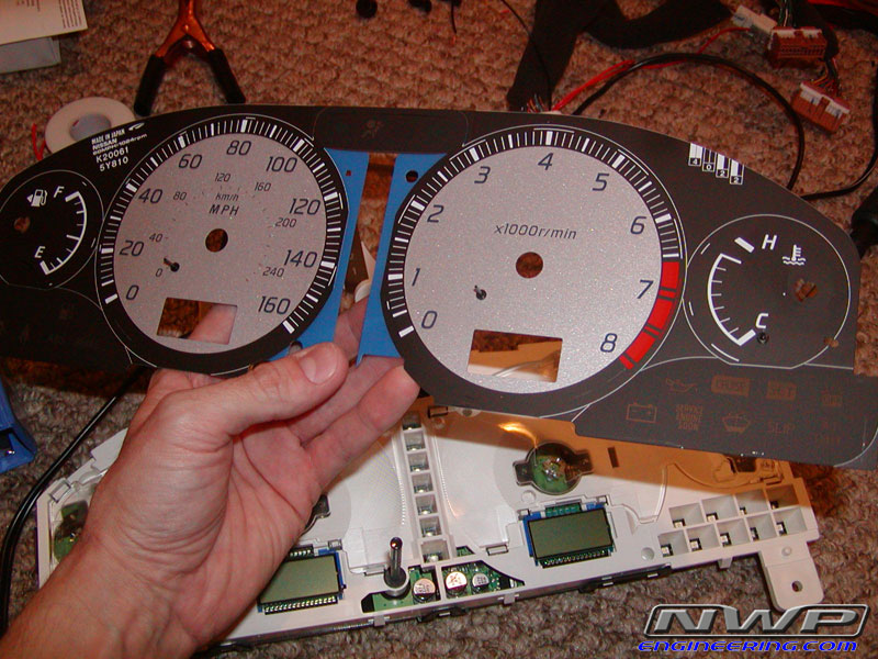
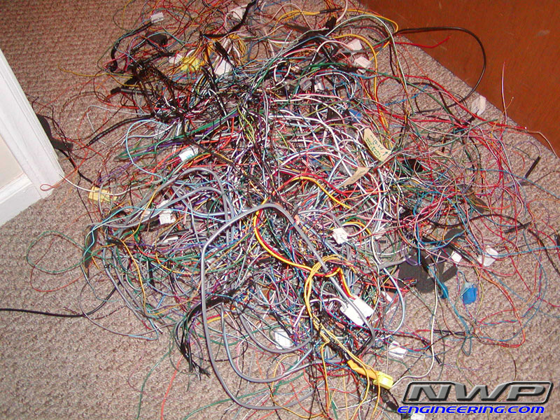
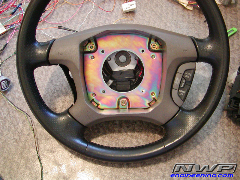
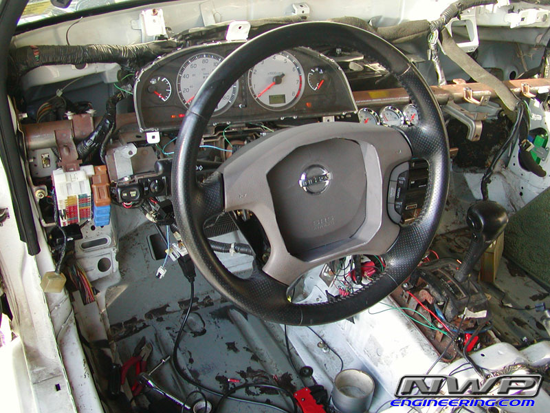
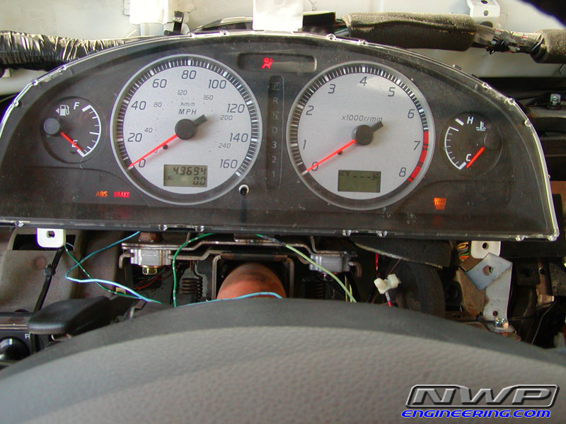
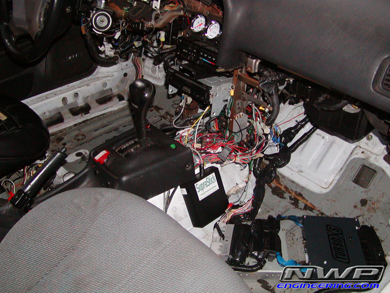
FULL ECU swap with 02 Maxima ECU, NATS, Ignition Switch, Steering wheel, & Cluster
Go Fast Mods and Engine Specs
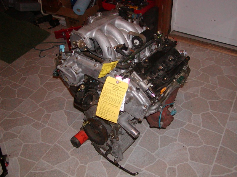
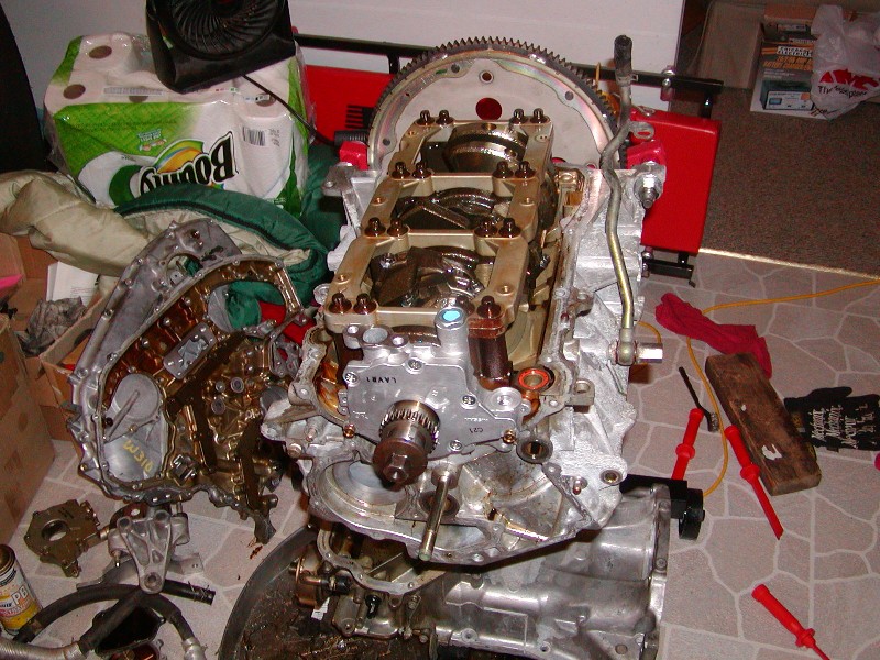
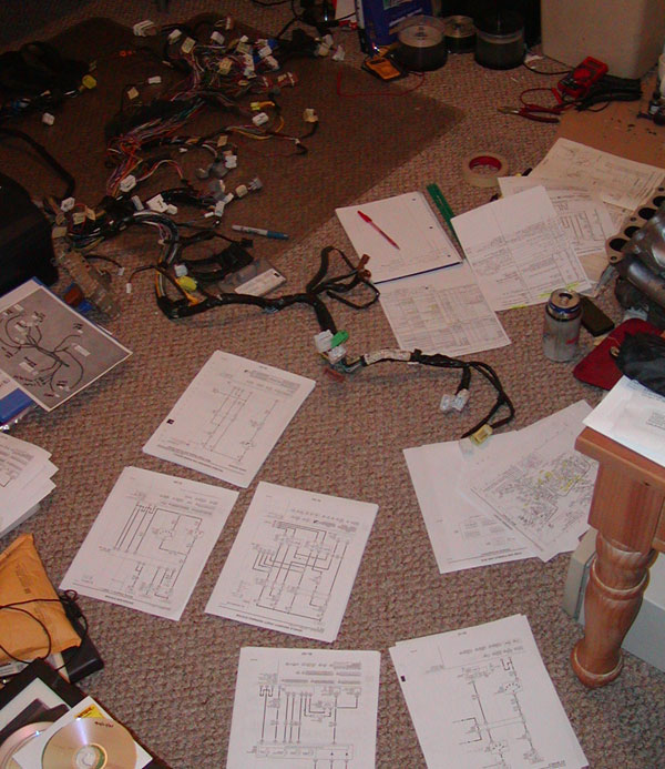
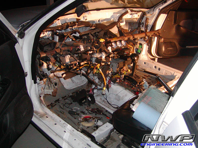
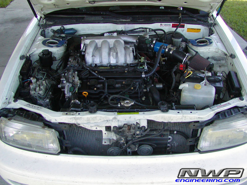
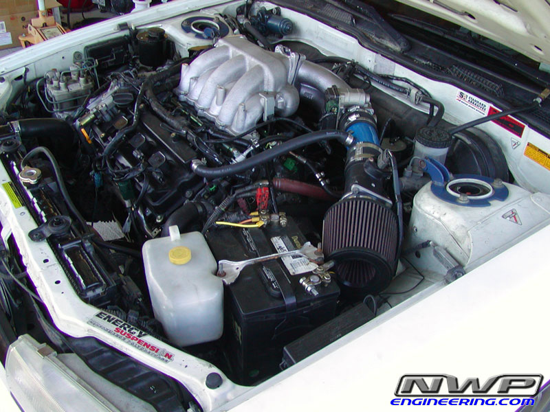
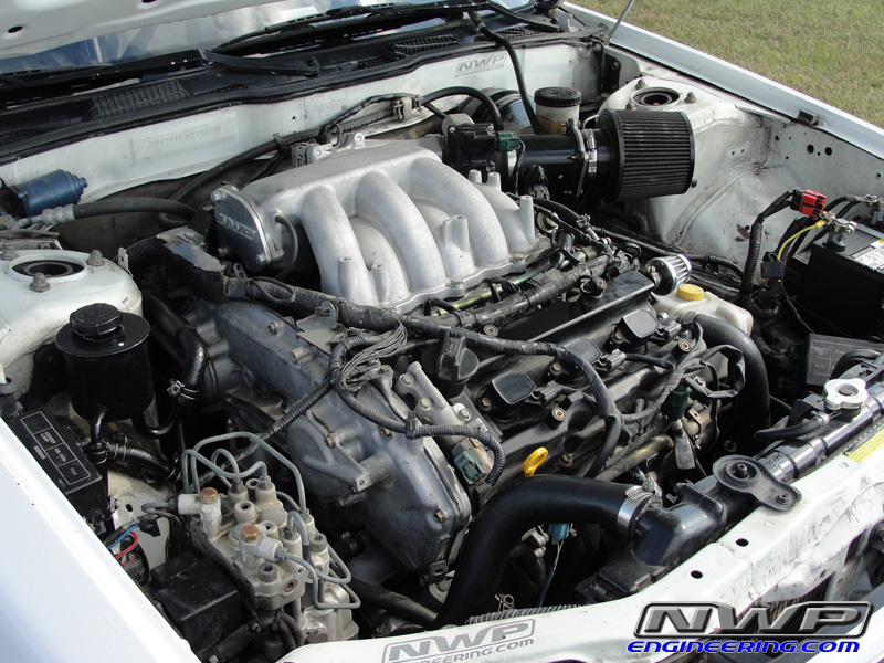
VQ35DE Engine Swap with FULL ECU wiring
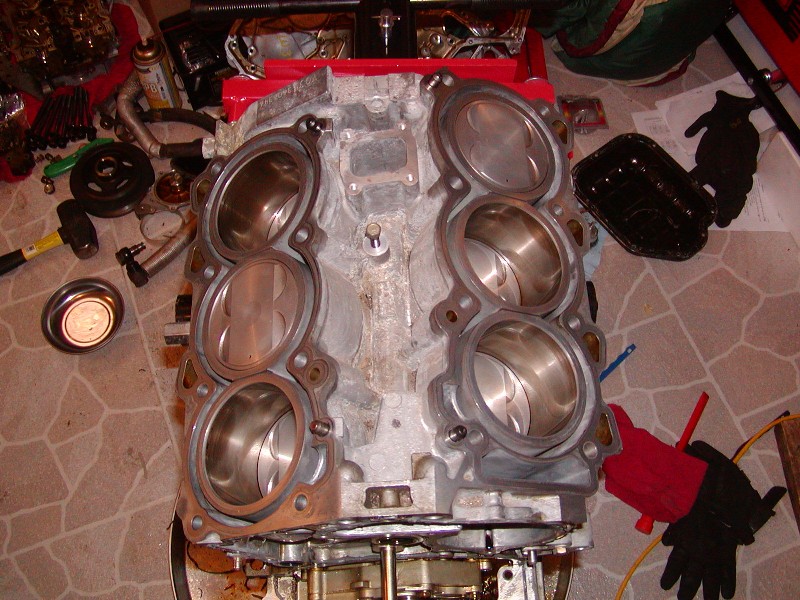
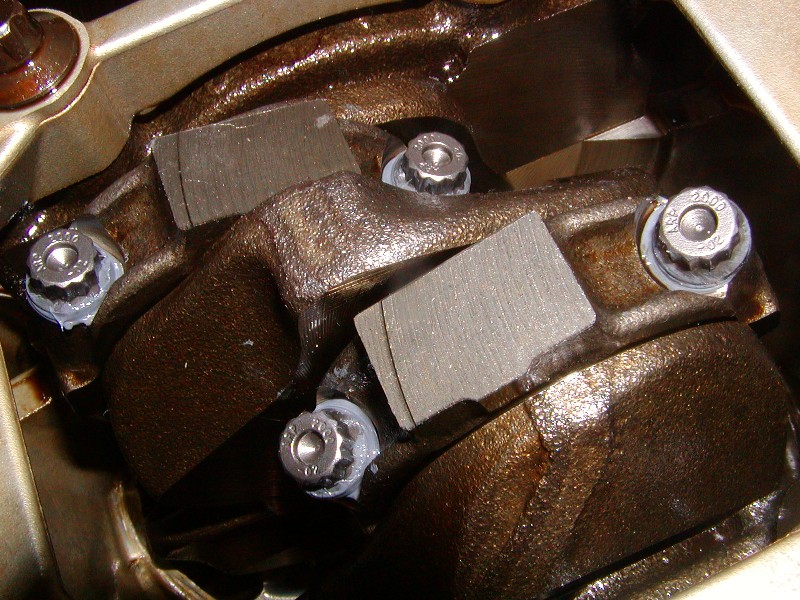
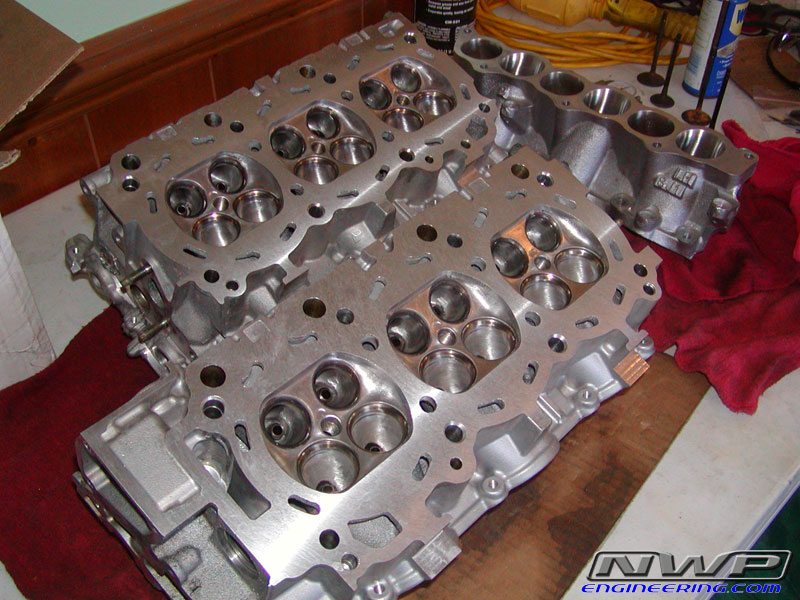
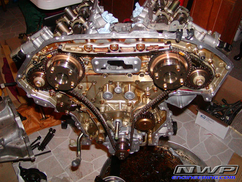
Fully Built Engine by NWP Engineering
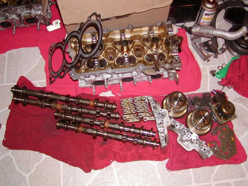
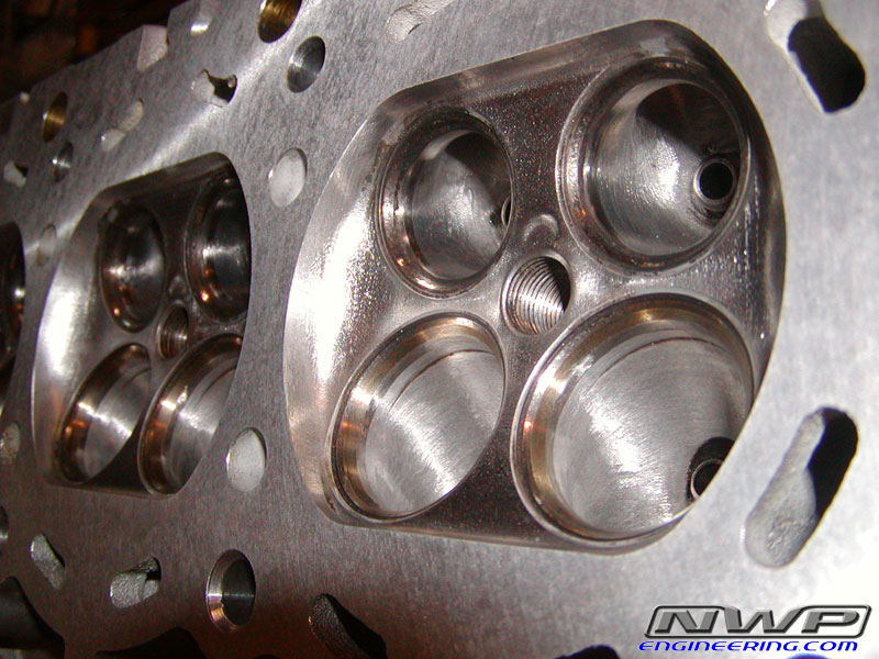
Full Headwork by NWP Engineering (port & polish, intake ports matched, all obstructions removed, valves lapped, heads resurfaced, combustion chambers polished)
All Intake Manifolds ported and polished and matched by NWP Engineering
Upper Intake Manifold completely gutted and smoothed out
NWP 75mm Big Bore Throttle Body Kit
NWP Engineering Thermal Intake Spacers(To prevent thermal transfer of heat from lower intake manifold to upper manifold)
NWP Engineering Premium VIAS Block Plate
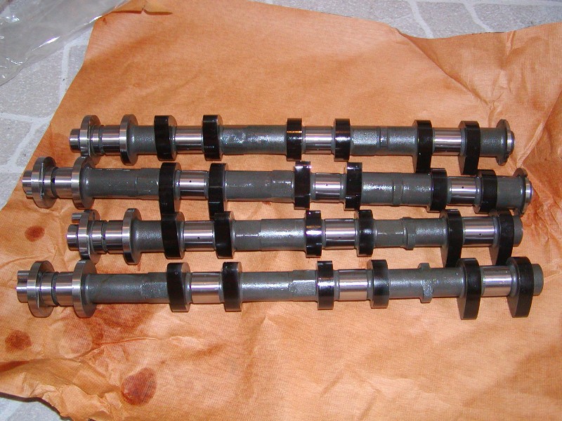
JDM Camshafts (260* duration & 10.9mm lift)
VQ35HR Head Gaskets w/ coolant passage modified on block (better coolant flow)
VQ35HR Valve Springs w/ an extra 1mm shim
VQ35HR Head Bolts
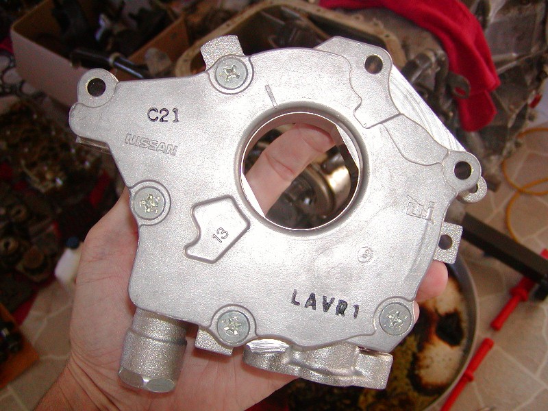
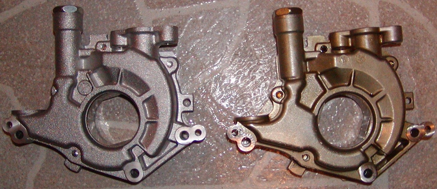
VQ35DE 06 350z RevUp Oil Pump
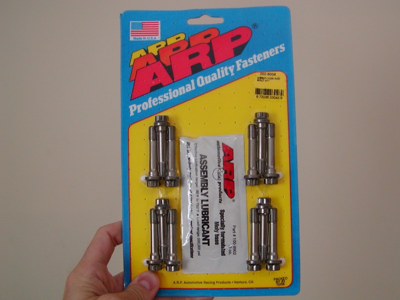
ARP Rod Bolts
New valve seals
R35 GTR Injectors (~560cc)
Walbro 255lph HP fuel pump
Nismo SR20DE Adjustable Fuel Pressure Regulator mounted on fuel rail in place of damper for a return style system (set to static 51psi)
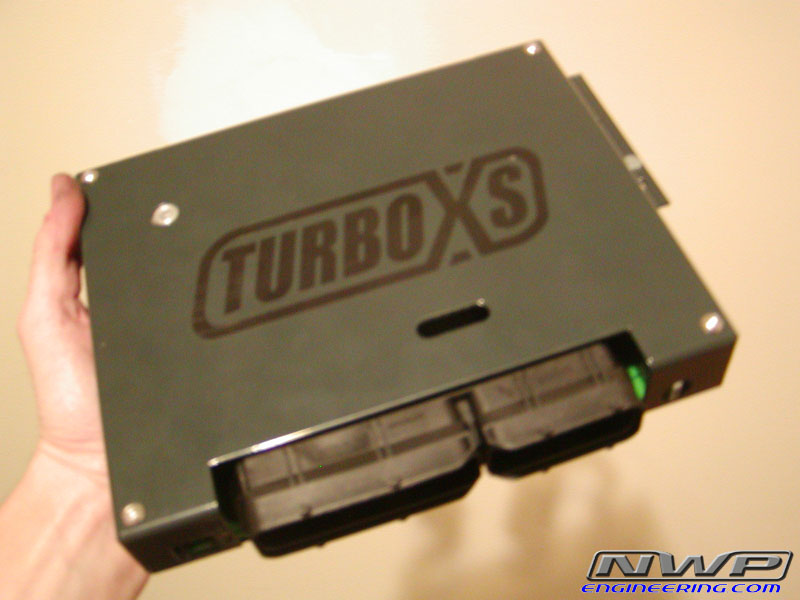
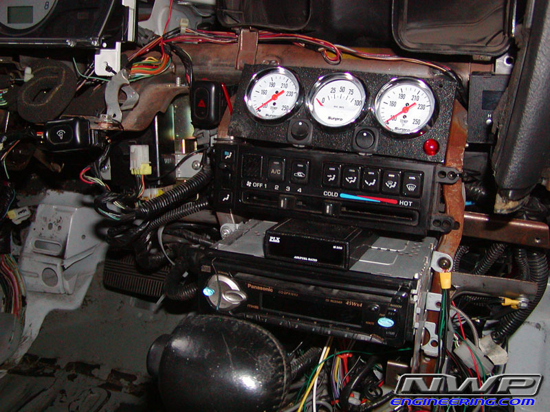
Turbo XS UTEC Engine Management System
Fully tuned by National Speed, Inc in Wilmington, NC
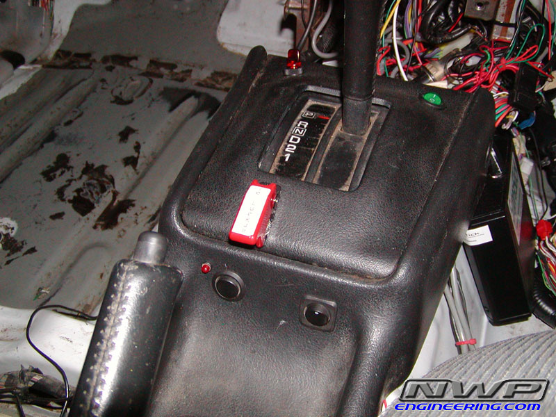
Suprastick V4 Standalone Automatic Transmission Control Unit
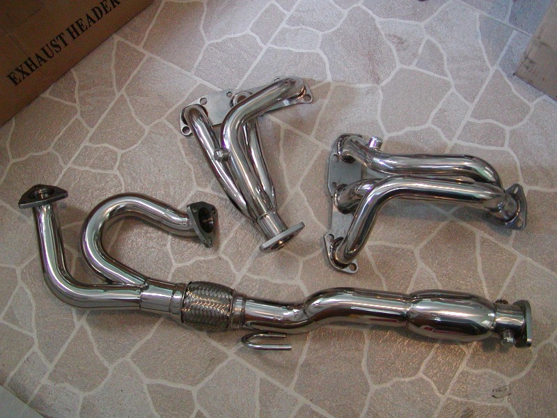
Custom Equal Length Mandrel Ypipe made by RJ’s Custom Piping
McCord Power Plate Electric Exhaust 2.5″ Cutout
3.5L Altima aftermarket headers (modified to fit engine bay)
K&N Cone Filter
3.25″ ID MAF Housing
TransGo HD2 Shift Kit Valve Body Recalibration
Edge Racing 3800 High Stall Prototype Torque Converter
Custom Engine Tune program by NWP Engineering for 93 octane
Stock heat range NGK copper spark plugs (stock gap)
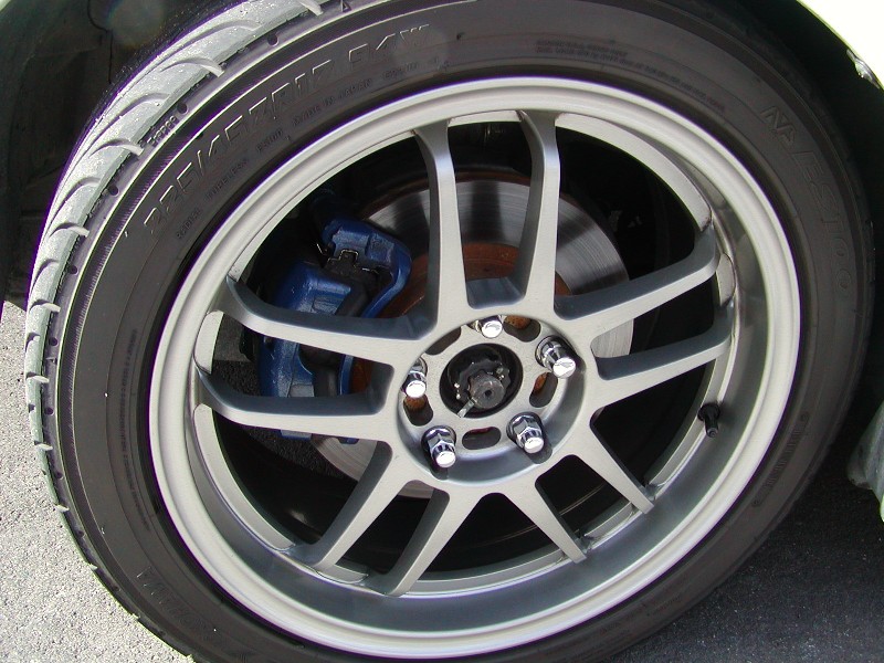
15×8 Rota Slipstream wheels w/ 22x8x15 Mickey Thompson ET Drag Slicks OR
14×6 OEM Ford Ranger wheels w/ 20x8x14 Mickey Thompson ET Drag Slicks
My SPAL fan recently had an issue due to some wiring that made contact with the headers. It caused the two wires coming out of the fan itself to touch and it ended up ruining the fan motor. So this time around I decided to go with the SPAL 14″ 1864 CFM fan. Primarily because its a little smaller in size and give me a little more clearance with my 5thgen Maxima supercharged setup. The CFM is good enough. I also have a small 10″ fan as well (not SPAL) but just as a backup.
Make sure you use a good relay (at least 40 AMP) before connecting directly to your OEM harness.
Fan Part Number:30102042
Fan Price: Between $120.00 -$140.00
Specs:
Model: 30102042
Airflow CFM: 1864
Profile: High Performance
Blade: Curved
Push/Pull: Pull
Height: 15.04″
Depth: 3.45″
Width: 14.45″
If you don’t use a good relay like the one above, this will happen (Photo Courtesy of Javon Bennet)
I was shopping around for quality fans for my Nissan Maxima’s (6thgen and 4thgen). The dual Mishimoto fans were not cutting it anymore. And honestly, the Mishimoto fans were really no different than the 14″ generic ones on eBay. I did some research and found a company called SPAL. A fellow member (Javon B.) vouched for these fans confirmed they work very well. All 12-volt puller models, these Extreme Performance Electric Fans offer the most flow and fan area.
My car would overheat at times when going on long cruises with the AC on. I no longer have any cooling issues at all. This fan is very powerful with 2,024 CFM and does the job with just single 16″ Fan. I’m not even using a shroud.
Make sure you use a good relay (at least 40 AMP) before connecting directly to your OEM harness. More info below:
Fan Part Number: 30102049
Fan Price: Between $100.00 -$130.00
Relay Price: It’s about $33 bucks. The part number for it is SPAL-FRH. It’s a 40-amp relay kit. Highly recommended. You can use your own relay brand as well.
Specs:
Type: High Performance – 12V Puller – Curved Blade
CFM: 2024 cfm
Height:16.22″ (412mm)
Width: 16.22″ (412mm)
Depth: 3.45″ (87.6mm)
Model: VA18-AP71/LL-59A
Made in Italy
Old 14″ Mishimoto Fans. These were 1300 CFM but certainly didn’t feel like it.
Comparison of my 16″ SPAL Fan to Mishimoto 14″ Fan
Mounted on `Mishimoto Radiator. It’s literally a perfect fit.
Dimensions
Photo of the SPAL-FRH Relay (40AMP):
If you don’t use a good relay like the one above, this will happen (Photo Courtesy of Javon Bennet)
I just had the y-pipe installed today (5/2/98), so I have not been able to completely test it out, but my overall impression is very positive.
The installation took 2.5 hours (cusom design/install) and involved the cutting and re-welding of several components of the exhaust system. The O2 sensor was moved, and some new piping was added.
My first impression has been that the engine reves MUCH more smoothly and quickly. It also seems to run smoother at higher RPMs. Noise has not increased very much, but I did notice a difference.
Pictures:
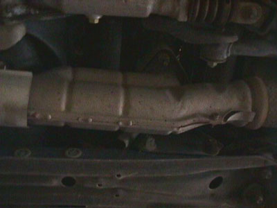
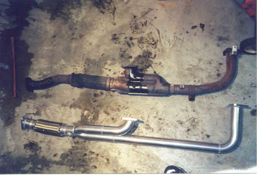
Stock Y-pipe:
You can see that the stock y-pipe has two main sources of restriction. First, the runner from the rear exaust manifold heads towards the FRONT of the car before it enters the y-pipe at a 90 degree angle. Second, the stock y-pipe is made of two halves that are welded together, this does not allow a smooth coupling of the pipes.
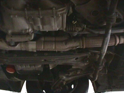
Stock Y-pipe Removal:
A Sawzall and a cutting torch were used to remove the heat shields from the stock y-pipe. Then the stock y-pipe, the flex tube, the O2 sensor, and the mounting flange to the rear exhaust manifold were removed.
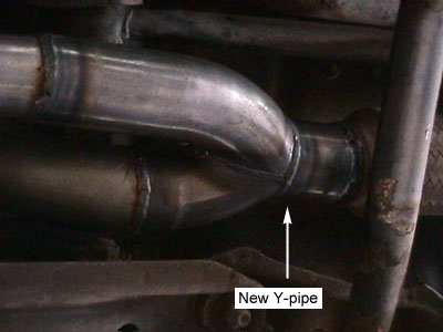
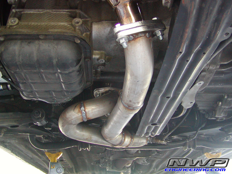
New Y-pipe Installation:
The rear exhaust manifold mounting flange was saved and welded onto the new y-pipe.
The O2 sensor was re-attached between the flex pipe and the catalytic converter. The O2 sensor was relocated because the flex pipe had to be moved 3″ towards the rear of the car to make room for the y-pipe.
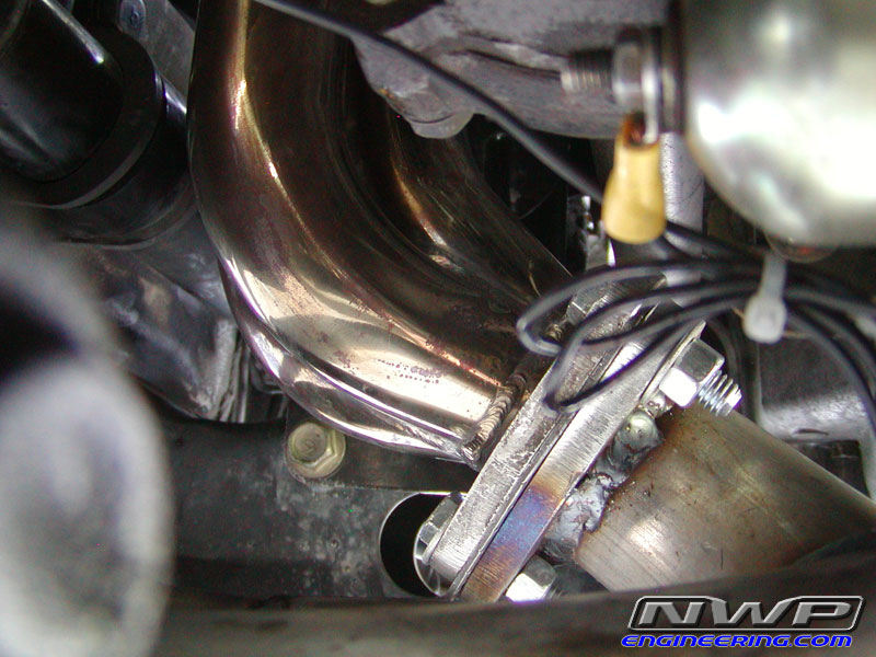
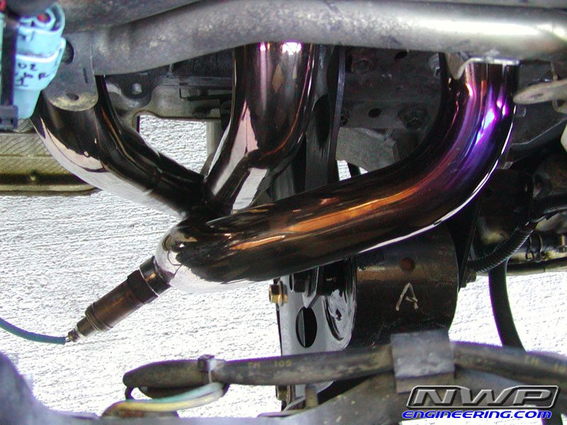
In this picture you can see the new Y-pipe. It is made out of mandrel bent stainless steel.
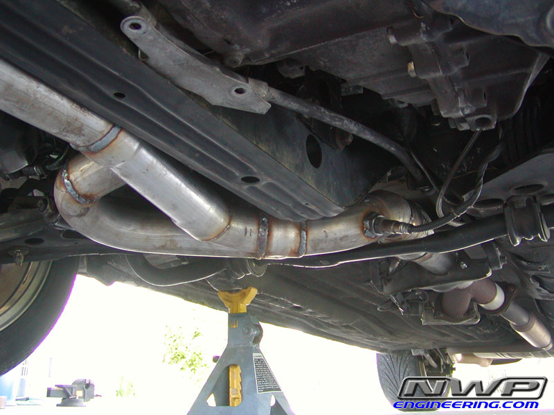
Finished Installation:
Here you can see the entire system. It is made of larger diameter tubing than the stock system, and the front and rear pipes come together in a less restrictive coupling.
All of the weld joints were painted to prevent rust.
Below are the procedures that I used in performing the replacement of six of my fuel injectors. I put them on this web page to serve as guidance for you, but do not guaranty the results nor do I proclaim this is the correct procedure, though I reference the Nissan Factory Service Manual, hereinafter (“FSM”), throughout. If you have any doubt on your capability in performing this replacement, take your car to a certified mechanic.
What you need : 1. Upper intake manifold gasket; part number 14033-89E00
2. Lower intake manifold gasket; part number 14032-89E01
3. Throttle body gasket; part number 16175-89E10
4. A.A.C valve gasket
5. New / remanufactured fuel injectors
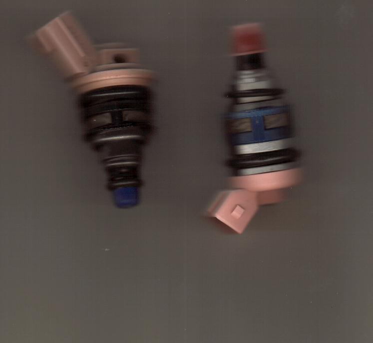
a. see the picture below, which depicts the two injectors with different connectors. b. The 90 -91 injectors have the metal clip (smaller) harness connector and the 92-94’s have clip-type (bigger) harness connector. c. Also, Nissan made both blue and black dot injectors for our cars. I have been told you can use either one, but can’t mix and match. I doubt it would hurt mixing and matching though, just so long as you get the right one for your car. The dot is on the harness connector. d. I picked up my remanufactured units for $37.95/ injector after the core deposit refund from Direct Automotive Product.
The injector on the left is a 92-94 injector, and the right is a 90-91, and probably an 89 too.
The steps I performed : 1. Release fuel pressure to zero
a. I did this by unhooking the upper hose from the fuel filter after pulling the fuel pump fuse
2. Separate the accelerator cables from the throttle body.
a. they easily just slide off. Tilt the butterfly valves back to get them.
b. Remove the cabling and routing from the intake plenum.
3. Remove spark plug wires from spark plugs.
4. Remove the intake elbow leading to the throttle body.
a. there are three bolts, the middle one is the longer one and routes the spark plug wires.
b. These bolts are torqued at 13 – 16 ft lbs.
For steps 6 – 9, basically remove necessary hoses and vacuum lines so you can free the plenum for removal. I took notes on a few of the items I might have forgotten when putting things back together.
5. Remove the A.A.C. valve
a. there are four 5 mm hex bolts holding this in. remove the harness connector also.
b. There is an “S” shaped hose connecting the AAC valve to the plenum, remove this also.
6. Disconnect throttle sensor
7. Disconnect the P.C.V. hoses behind the intake plenum
8. Disconnect vacuum hoses under the throttle body, from the E.G.R. control valve, master brake cylinder ,etc.
9. Remove the E.G.R. flare tube
a. this is held on by two nuts. I think they are 10mm in size.
10. Remove the upper intake plenum
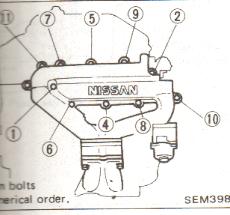
a. there are eleven six millimeter hex bolts that hold down the plenum at 13 – 16 ft lbs.
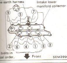
b. There is a special torque sequence that I observed in both loosening them and tightening them down. Please refer to the picture at the bottom of the screen for that sequence.
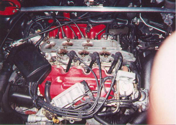
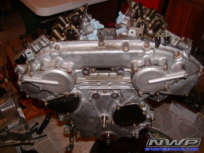
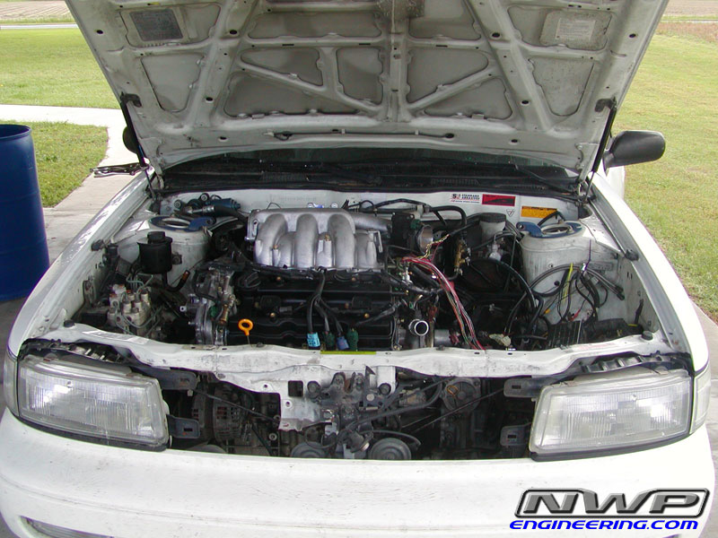
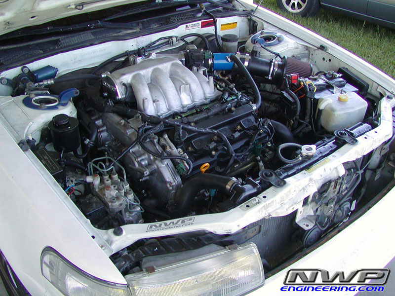
Less the spark plug wires and the throttle body (my procedure keeps it attached to the plenum), your engine should look something like the above before taking the lower intake manifold off. Pictures are courtesy of Matt Blehm.
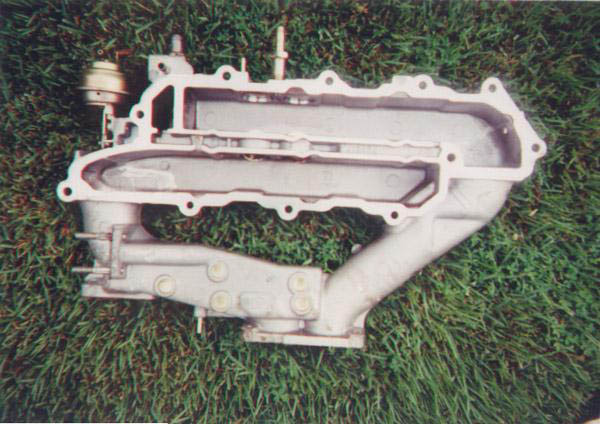
11. Remove the lower intake manifold collector from the engine.
a. Use the loosening sequence below for taking the manifold off and putting it back on. Again, reference the picture at the bottom of the screen.
12. Remove the engine earth harness from behind the plenum.
13. Remove the fuel injector harness wires
a. For the 92,93,94’s this is easy, as you just apply pressure on the harness and pull
b. For the 90 and 91’s (and presumably 89’s) there is a metal wire clip that you must pull out or partially out to remove the connector.
14. Remove fuel injector(s)
a. I used a pair of pliers and gripped them tightly, turning the injectors back and forth before pulling upward. All came out somewhat easily, except my last one.
b. There should be two O rings per injector for the 90 -91 injectors. I am not sure the 92,93,94 injectors have two. The lower O ring will likely stay in the fuel rail hole upon removal of the injector. Just stick your finger in and retrieve it. Be sure to replace with new “O” rings, per the FSM.
15. Replace injector(s)
a. I applied motor oil to the O rings and carefully inserted the new fuel injector. Instead of just pushing downward immediately, you should turn it back and forth, while applying downward pressure. You will see and feel the injector seat in how it should be. Before replacing, assure that the new ones spec out correctly with regard to resistance. The range of resistance allowed by Nissan is 10 –14 ohms .
16. Clean intake plenum, lower intake manifold, and intake runners.
a. I used Carb clean and a Valvoline product. I sprayed a good amount of Carb clean down the intake runners and used a cloth to wipe the dirt out. You may want to try a toothbrush.
b. Be sure to completely scrape away all remaining gasket material on both surfaces so as not to allow an intake leak after assembly.
17. Reinstall all parts in reverse order, keeping in mind the torque sequence and use the torque wrench so as to tighten the following to these torque specifications, per the FSM:
a. plenum hex bolts 13 – 16 ft. lbs .
b. lower intake manifold hex bolts, 13 – 16 ft. lbs .
c. A.A.C valve bolts – 4.6 – 6.1 ft lbs .
d. intake elbow bolts 13 – 16 ft. lbs .
The online HTML editor now supports the use of an external CSS file to be applied to format the content of the visual preview of your document.
This procedure is for the installation of an underdrive pulley. This requires removal of all 3 drive belts and possibly the starter. Nissan recommends changing drive belts every 30,000 miles. They should be checked periodically too. This procedure applies to the VE30DE engine, but is very similar for the VG30E.
My car was leaking oil out of the front main seal (behind the crankshaft pulley) so I figured if I was going to have to take off that pulley, I should go ahead and put a better one back on. For the VE engine (1992-1994 SE only), ASP Racing sells a lightened, smaller crankshaft pulley:
Auto Specialties underdrive pulley systems increase engine horsepower by reducing the amount of power required to drive external accessories. For example, the alternator, power steering, water pump and air conditioner all rob horsepower from the engine. By replacing factory-sized crank and accessory drive pulleys with a resized pulley, the accessories are slowed, resulting in more horsepower available to drive the rear wheels. Typically, a set of Auto Specialties street pulleys will increase output by 12 to 15 horsepower, resulting in quarter mile time improvements of .2 to .25 seconds.
I got mine at RPMoutlet.com. For the VG engine (89-91 SE and 89-94 GXE), Unorthodox Racing sells a lightened, smaller pulley. You can get this from Courtesy Nissan. Because the new pulley is smaller, you will need smaller sized drive belts which run about $10 each from most parts stores. Here are the Gates parts numbers for the belts you need (note: ASP gives a different part number for the power steering belt, but this is the correct one). I got mine at PepBoys and they are Dayco brand; the numbers are easily converted to Dayco numbers – 325K5, 378K4, 460K4. The number next to K means the number of grooves in the belt and the other number has something to do with the length (probably the circumference).
VE30DE
VG30E
Alternator
K050323
K040292
Air Conditioning
K040460
K040460
Power Steering (also drives water pump)
K040378
K040395
As you can see, the new belts fit just inside the old belts:
Tools you will need:
Various sockets: 10,12,14 and 27mm (for the crankshaft pulley bolt); you may need one or two other sizes, but nothing special besides the 27
12mm open end wrench
Socket extension
Torque wrench
Breaker bar
Flat head screwdriver
Impact wrench would be very helpful, but not necessary
Maybe: pulley remover
This procedure isn’t that complicated, but if you haven’t ever changed drive belts, it may be a good idea to have someone else check over your work before you put everything back together (especially important for power steering and alternator belts). Read through the instructions first before beginning any work. Also, you should buy a new front oil seal for your car. It’s about $3 from Courtesy Nissan and maybe $5 or 6 from a local dealer; you’ll have everything off to change it and you wouldn’t want to have to do this again if it starts leaking in a few weeks from now. The part for the VE engine is 13510-97E10; I’m not sure of the part number for the VG.
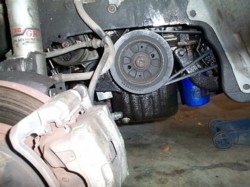
First, remove the right front wheel and remove the splash shields that cover the side and below the drive belts. There are a couple 10mm bolts holding these on. You should now be able to see the crankshaft pulley and drive belts
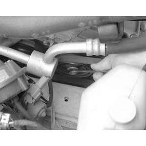
Start by loosening the 12mm bolt on the air conditioner’s idler pulley – this is the small pulley just in front of the A/C compressor. This will be more of a pain if you have ABS, but it’s still not that bad. I used the flat open end of a 12mm wrench to get the bolt and then loosed it that way. Dont remove this bolt, just loosen it a few turns. Now there is a bolt pointing straight up just behind that pulley that you need to adjust to move the pulley down (see picture below). If this bolt is hard to turn, make sure the bolt through the middle of the idler pulley is loose enough; dont force it or you could damage the idler pulley tracks. You need to lower it enough so the belt has enough slack to pull off of the A/C compressor. The pictures below are with the large radiator hose removed so you can see where the bolt is.
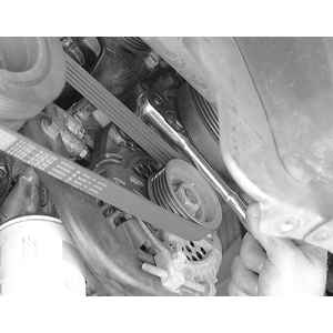
Now you need to remove the alternator belt. Loosen (do not remove) the bolt at the bottom of the alternator that goes into the alternator adjustment bolt (first picture). Also, loosen the alternator pivot bolt near the top of the alternator (second pic). Now you can loosen the alternator adjusting bolt (third pic). In my case, the bolt loosened but alternator did not move, just move the alternator with your hand to the point where the bolt is tight again. Loosen this until you can pull this belt off.
Now you need to remove the power steering belt (which also runs the water pump). There is another idler pulley for this system. Just loosen the center nut for that and lower the idler pulley until you have enough slack to remove the belt.
If you are not putting on an underdrive pulley and just want to change drive belts, skip the next couple steps:
Remove bolt in the center of the crankshaft pulley. This is where you need the 27mm socket. This bolt is on very tight; if you have an impact wrench, this is a great time to use it. Otherwise, you’ll probably need a long breaker bar. Chiltons recommends removing the starter and placing a flat blade (your hubcap removal tool in your Nissan jack set in the trunk should work fine) in the teeth of the flywheel/driveplate.
If you have a manual transmission, put the car in 5th gear. The starter is easily removed; if you are going to remove it, you should unplug the negative terminal of the battery first so you dont short anything while removing the starter’s power wire. The starter is only held on by a large wire, one 14mm nut and one 14mm bolt.
If you remove the rubber protective covering over the large wire, you will find a nut under there; just remove that and the large wire will come off. You will also need to unclip a smaller ground wire from it’s harness. Then you can remove the 14mm nut and bolt that hold the starter onto the transmission. After these are loose, the starter will just pull off and you should be able to see the flywheel.
If you have an automatic, there should be a small cover over the lower part of the transmission that you can remove to see the driveplate.
Then wedge something in between the teeth and prop it against something solid. You should now be able to break loose the crankshaft pulley bolt.
Now you can remove the crankshaft pulley. Mine could be pulled off by hand; if not, a 2 or 3 jaw puller can be used to pull it off. You will notice how much larger and heavier the stock pulley is compared to the new pulley.
The old oil seal needs to be removed now. It is just around the inner edge of where the pulley was. Use a flat head screwdriver to gently pry this out. Be very careful not to scratch or damage anything other than the seal. Now the new seal just needs to be pushed in place (you should lube the outer edge with some engine oil, the inner edge is already lubed). Put it in place and gently push the edges in; I used a rubber mallet to help push it in. The first picture shows the seal still on and the second shows the seal removed.
The new pulley will be very tight to get on. Some have hammered it on, but I would NOT recommend this. I used my dremel to shave off some material from the inside diameter until it fit better. On mine, I could feel a small difference in diameter between the inside edge of the new pulley and the rest of the inside diameter; I ended up dremeling the inside until it was all the same diameter as the end portion. Just use sandpaper, a dremel or whatever to remove a small amount of metal in there, but try to do it in a circular way so it’s even throughout. When I was done with this, the new pulley fit on better. I got it on part way and then put the large bolt in the middle and tightened it to help push the pulley on. Now you need to torque the pulley bolt to 123-130 ftlbs for the VE or 90-98 ftlbs for the VG. You can now put the starter back on (or cover plate for the automatic tranny). Also, you can now reconnect the battery if you unplugged it.
Now you are ready to put the belts back on. This is just the opposite of how you removed them – put new belt over the pulleys and tighten the adjustment bolt and then tighten a bolt to lock the adjustment (and for alternator, tighten pivot bolt). If your belts are too loose, they may make a squeling sound when you start the car and may slip a little. If they are too tight, they could cause lots of other problems so it’s important to get the tension right. The picture below shows the test point for each bolt as indicated by the arrow. If you push or pull down on this point it should move a certain distance for each new belt. Alternator: 6.5-7.5mm, A/C: 5-6mm, power steering: 6.5-7.5mm. This is where it would be helpful to have someone who has done drive belts before to check the tension for you to be sure.
Once the belts are on and tighten, check the 2 idler pulleys and the alternator adjustment bolts to make sure they are all tight. Start up the car and take a look at the belts and pulley. My pulley looked like it was a little off center, but I realized it was just the washer in the middle of the pulley was tricking me because of the silver color of the pulley and the black of the washer. Look at the edges to be sure. Check that all the belts are turning smoothly and are not at all crooked or not in their grooves. Now just replace the splash shields and that should be it. Check the pulley and belts again in a couple days just to make sure everything is still in place.
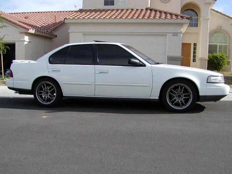
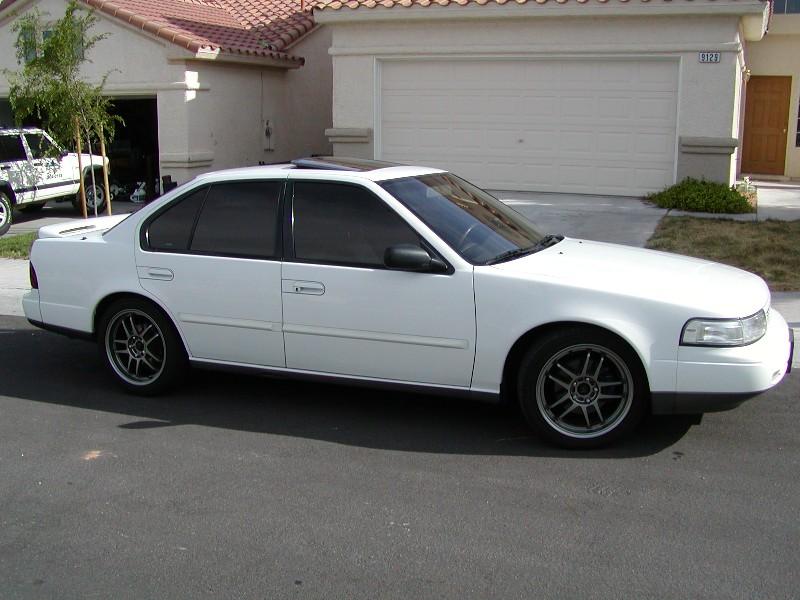
I had a custom “y pipe” for my older white Maxima. In actuality, it is an “f” pipe that aids in the exiting of exhaust. Unlike a true Y pipe, the rear manifold exit drops down straight into the pipe from the front manifold. The exhaust gas is freer flowing and it certainly made a difference, but not as much as the true Y pipe.
I did things differently with my black car. I wanted it to be faster and more responsive than the white Maxima and I have accomplished that. I installed the Cattman Y pipe. It is a completely bolt-on piece that was not terribly difficult to install. I recommend taking the time and soaking all the bolts/nuts prior to taking them off. You will also need to purchase exhaust gaskets, which are also shown in my installation pictures below.
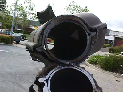
In comparing the pipes, you can see how the flow is impeded in the stock pipe. Also note that the Cattman pipe has a longer drop from the front manifold. I believe this causes a problem with the pipe hitting the sway bar. Also note how the stock pipe drops a bit in order to get to the Catalytic converter, this just goes to show you that the stock pipe sits higher. If the Cattman pipe would have incorporated these two things I mentioned, it would have plenty of clearance from the sway bar. I believe Warpspeed performance solved this aggravating problem.
Tools you will need:
1. Metric Socket set (some SAE may actually work though, as I found out for my front catalytic converter bolts)
2. Metric wrenches (to reach up in some of the more difficult bolts
3. Breaker bar (at least an 18 inch socket wrench as these bolts are tough to take off)
4. Liquid Wrench spray (or a similar product- I used a synthetic Valvoline product)
5. 3 gaskets (two for the manifold connections, and the other for the catalytic converter.
5. Goggles! (else you’ll get all kinds of crap in your eye)
6. A light for under the car
7. Duct tape and aluminum foil if it hits your sway bar after your done (because of a soft rear motor mount)
8. A jack and jack stands
Here’s the pipe and the gaskets I used.
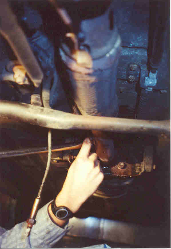
Step1 : Patrick using the lubrication. Valvoline synthetic lubricant was used to loosen all bolts. My advice is to let them soak on the bolts for a few hours prior to trying to remove them. This will make your job much easier.
Step 2: Yours truly, taking off the shields and brackets. At this point, the jack in the picture is a backup in case my jack stands fail, don’t worry, no upward weight on the transmission there.
Step 3 : Using the breaker bar to take off the Catalytic converter bolts.
Step 4: Loosened those nuts on front manifold.
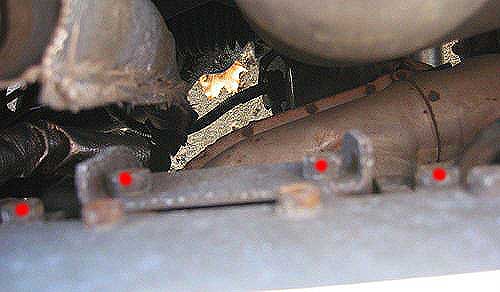
Step 5: Instead of taking this bracket off like the most of you probably did, I took my electric hacksaw and sawed off the end of it, giving the Y pipe just enough room. Note how the bracket will work with the crossmember and help absorb an impact if I hit something low. Pictured is me holding the piece that I cut off.
Step 6 : Note that the Y pipe is protected both by the bracket and the cross member. I was lucky to get one that did not hang lower than the cross member. However, the sway bar problem that I have and that I mentioned in my FAQ’s could have been avoided if this drop wasn’t so severe. It looks like there is plenty of clearance now, but the car/engine is jacked up somewhat. This is how it should have been!
Step 7 : The finished product, before hooking up the catalytic converter hangers.
The result? A lot more power between 3000 and 4500 rpm, however, the pipe hangs too low and vibrates on the sway bar during moderate to heavy acceleration. I ended up passively fixing the problem by padding the sway bar. In addition to my padding of the sway bar, I had to dent the pipe a little bit.
Extract or delete some HTML tag attributes from the desired tags, based on your criteria with the online HTML editor. Other useful features will help you to make web content composing a piece of cake.
A) A knock sensor is a specially designed listening device for car engines. It listens for engine knock, or detonation (pinging). Detonation can be very bad for an engine and is the result of the fuel/air mixture exploding too quickly instead of burning evenly and rapidly. This is due to either bad fuel, ignition timing which is too high, or built up carbon deposits in the engine (which increases the compression ratio). The sensor is small and consists of a piezoelectric sensor that listens for knock by detecting pressure. It is very sensitive and can be considered worthless if dropped. The vibrational pressure is then converted into a voltage and sent to the ECU for evaluation.
Q) How do I know if my knock sensor is bad?
A) Symptoms of a bad knock sensor include a sluggish engine, poor acceleration and poor fuel economy. Knock sensors rarely fail outright and more often get “soft” over time and cause false signals to be sent to the ECU, which thinks the engine is knocking when it’s really not. Thus, the ECU will reduce the ignition timing to the engine. The knock sensor on the VE30DE is prone to corrosion of the terminals and harness connection. This is due to the harness weather seal getting brittle and cracking, allowing moisture to seep into the harness from the rear and corrode the terminals. This creates a poor connection and faulty voltage readings to the ECU.
Q) How do I test my knock sensor?
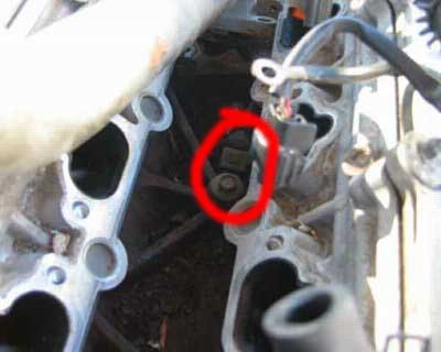
A) The knock sensor voltage can be checked through an electrical harness located right above the thermostat housing (where the lower radiator coolant hose attaches to the engine). It is a gray connector with an orangish red cap with two wires. Unplug the connector and attach a multimeter (or voltmeter) to the lower harness (the male connector). The wire for this connector should go left and underneath the intake manifold. Check the front most terminal (see pic) and ground out the negative point. You must have a multimeter than can measure more than 10 M ohms. Continuity should exist. This method is per the Factory Service Manual. NOTE : Knock sensors should be considered regular maintenance items. If you have over 100K miles and have never replaced the knock sensor, you can probably consider it bad.
Q) What parts will I need?
A) For knock sensor replacement only, here are the required parts:
-Normal hand tools (8, 10, 12mm sockets, long extensions, 14mm open-end wrench, large adjustable wrench, torque wrench, Philips screwdriver, 6mm hex key socket (I THINK this is right, check the size of the intake plenum hex bolts first to see if it fits before you start)).
-Coolant and distilled water (about a gallon total)
-Knock sensor PN 22060-30P00
-Knock sensor sub harness PN 24078-30P00
-Throttle body gasket PN 16175-53J00
-Intake plenum gasket PN 14032-97E00
-2 Intake manifold gaskets PN 14035-97E00
-Liquid gasket which is impervious to coolant (high-temp)
Q) What are some other things I could do while I’m in there?
A) Since you will be draining some coolant and releasing the fuel pressure, here are some things you should think about doing (though not required):
-Replace all fuel lines with rubber fuel injection hose (don’t get normal fuel line since they are not reinforced for high-pressure fuel injection systems).
-Replace all coolant hoses (radiator hoses, bypass hoses, throttle body hoses, there are a lot of small ones that are very difficult to get to normally, this is your chance to do it easily)
-New vacuum hoses (you’ll need at least 8 ft I believe, there are a lot of small ones)
-Fuel injectors: Might want to get them cleaned and install new o-rings and grommets
-Fuel filter, since the fuel pressure is released, why not?
-Port match intake manifold/plenum and throttle body
-New coolant temp sensor
-New PCV valve
-New thermostat
Q) I’ve never done major work on a car. Can I do this successfully?
A) Replacing a knock sensor isn’t necessarily hard work, but it is time-consuming. As long as you think the project over beforehand and label everything you disassemble, you should go fine. The worst thing that can happen is you end up with a loose hose somewhere or have an intake or coolant leak.
Now the fun part, actually doing the job! These procedures were produced from my 93 SE 5spd. If you have an auto, you might not have as many vacuum lines to disconnect since the 5spds have the power valve and purge canister.
Release fuel pressure
The FSM states that to release the fuel pressure, you need to remove the fuel pump fuse located in the interior of the car under the panel by your left knee when you’re sitting in the driver’s seat. Crank the engine up, let it die, then crank it a few more times until it doesn’t start. Then take out the key and replace the fuse.
Drain coolant
On the bottom right side of the radiator is the drain cock (plastic t-handle with a small clear rubber hose hanging down). Open the drain cock and allow about 3-4 quarts of coolant out. You don’t need to drain the entire engine since the intake manifold only holds a small amount of coolant, and this is the first part to drain since it’s highest on the engine. Remember to shut the drain cock!
Disconnect battery
Very important! You will have open fuel lines, so one spark could start a fire! Remember to disconnect the negative cable first.
Disconnect intake and air box
-Unclamp the 4 latches on the air box as if you were changing your air filter
-Loosen the throttle body air intake tube clamp
-Unclamp the two big rubber breather hose attached to the plastic air intake tube.
-Unhook the two vacuum lines attached to the resonator, then lift the entire air intake unit out and out of the way
Disconnect blow-by tube
This is the small, long metal tube attached to the front of the intake plenum
-Unbolt two 10mm bolts and two rubber hoses.
-Carefully unhook the wiring harness clamps. These are very brittle and if not already broken, will break if you force them! Have some zip ties ready if you do break them
Throttle Body
Just disconnecting the throttle body is the easiest way to do this. You can leave the TB attached but then you must remove many vacuum and coolant lines from it. It’s easiest just to remove it and lay it on the side.
-Remove the throttle and cruise control cables by loosening the left nut with your 14mm open-end wrench (furthest from throttle body, if you loosen the right nut you can change the tension on the cable, not good!). Then remove the cable from the TB bracket.
-Remove a short vacuum hose on the bottom of the TB that connects to the intake plenum
-Remove the 4 hex bolts using a criss-cross pattern and remove the TB
-For added stretch you might have to unclip the TPS harness from its mount
Intake Plenum
-Unplug and remove the three rear coil packs
-Remove three ground straps (10mm bolts) 2 on front of plenum, one on left side *Take a dremel or steel wool or something and clean these ground straps and mounts to get the oxidation off, these need to make good grounds!*
-Remove the vacuum hose from the power valve on the left side of the plenum (N/A for auto)
-Remove the tiny cruise control vacuum hose from the rear of the plenum
-Remove the mid-size vacuum hose on the rear of the plenum that routes to the brake booster
-Remove the mid-size vacuum hose right underneath that (this one meets a metal pipe which eventually winds up at the PCV valve.
-Now, remove the two 12mm bolts that this PCV metal pipe connects to the plenum with
-While you’re down there, remove the two 12mm top bolts of each plenum stiffening plate (only one plate is shown in the picture, there is another to the right by the EGR)
-Take your big adjustable wrench and crack the big nut loose on the EGR valve. Loosen it all the way until it moves freely and you can see a gap between the EGR valve and metal EGR tube
-Remove the 4 remaining vacuum lines by the throttle body location.
-This one’s hard to see, but there are 4 12mm bolts holding on the EGRC valve on the lower right side of the plenum. Two on the right side, two on the back side (one is not visible in the pic)
-Remove the 10mm bolt holding on a metal vacuum line mount on the right side of the plenum, in front of the throttle body. It has a yellow sticker on the mount.
-Now all you have to do is crack loose the 6 hex nuts in a criss-cross pattern and pull off the plenum! If it doesn’t come off freely, hit the “Nissan” part lightly with the palm of your hand. Now, when removing the plenum, make sure everything is disconnected before you rip something off
Fuel Rails
-Loosen the screw clamps for each of the 4 small fuel lines (2 on each rail)
-Remove the fuel “T” line on the left side by removing the two 10mm bolts. Be careful not to drop these down the intake manifold as you’ll have to fish it out of the intake port of the head if you do (speaking from experience here)
-Break loose the fuel lines and be prepared for some fuel to spill out. Have rags handy. Remove the fuel “T”
-Now remove the 4 hex bolts of the fuel rails. Be prepared to gather a plastic spacer and metal washer for each bolt as they will fall and get lost easily. Remember how they fit! Plastic washer on bottom, then fuel rail, then metal washer on top, then bolt.
-Lightly pull up on the rails, when they are loose you can remove the right fuel lines. Do not drop the fuel rails, injectors are fragile and expensive!
-Watch for any loose fuel injector grommets (where the fuel injectors sit in on the manifold). Don’t lose these unless you have new ones ready to go.
Intake Manifold
-Remove the left radiator hose and the smaller bypass hose right next to it. You only have to disconnect them from where they meet the manifold
-On the right side, remove the three bolts that hold on the coolant tubes to the right side of the manifold. You may have to pry a bit to get this off as it’s sealed on with liquid gasket.
-Disconnect the coolant temp sensors (big one and small one, be careful as these electrical connectors are brittle, and you’ll have to pry the small metal wire clip to remove it)
-Now crack loose the 4 nuts (not bolts yet!) in a criss-cross pattern, 2 on each side of the manifold
-Now loosen the 6 hex bolts, again in a criss-cross pattern (important, you don’t want to warp the manifold by improper untorquing)
-Make sure you gather the washers that go with the nuts
-Pop off the manifold (you might have to pry a bit)
Water Pipe
By now, you can see the knock sensor and the pile of crud in the valley of your engine, but there’s no way to break the sensor bolt loose because the water pipe is in the way!
-Remove the two nuts and washers on the left side (connecting to the water pump)
-Remove the two bolts that bolt vertically down into the engine block on the right side.
-Now, using a LARGE flathead screwdriver, pry the water pipe off the studs on the water pump side and you’ll be able to hold the water pipe up to get to the knock sensor. Much easier than removing the thermostat housing and all those coolant lines on the right side
Knock Sensor
Finally, one bolt and it’s off. Clean the contact point thoroughly since any dirt or gunk will make the sensor less effective. Now, put the new sensor in and BE CAREFUL with it. Remember not to drop it or hit it against anything. Even when bolting it down take extreme care, you do NOT want to over tighten it! I couldn’t find a torque figure in the FSM so I just tightened it down until I felt resistance and went about another half turn. My uncalibrated torque right arm says it was about 15-20 lb/ft.
Now it’s time to clan the gasket surfaces on the head, manifold, plenum and throttle body. Use a paint scraper for the best results. A bit a steel wool won’t hurt either. Make sure no debris or anything falls into the intake ports in the head. Also clean off the water pipe where it was sealed with liquid gasket
Installation is in the reverse order of removal. Use a solid bead of liquid gasket on all surfaces. Completely circle around all pipes (on the right side of the intake manifold, the coolant pipes that attach have two pipes. Make a circle around each hole so they don’t leak into each other). Don’t use TOO much liquid gasket though. A thin solid bead is all that is needed. Allow at least an hour for it to dry (by the time you get everything else back together, at least an hour will have passed)
Intake manifold torque for the hex bolts is 20 ft/pounds. For the 4 nuts it is 24 ft/pounds.
Again, torque them in a criss-cross pattern (middle bottom left, middle top right, middle bottom right, middle top left, far bottom left, etc)
Fuel rail bolt torque is 20 ft/lbs
Intake manifold hex bolt torque is 20 ft/lbs. Criss-cross pattern.
Throttle body torque is 15 ft/lbs, criss-cross pattern
Make sure you replace all the plastic spacers and washers correctly when you replace the fuel rails.
When replacing your coolant, fill it up to the top of the radiator cap. Now, carefully open the 10mm nut by the large coolant bypass hose on the right side of the intake manifold (by the two pipes and the coolant temp sensors). This is a purge valve and releases the air in the system as you fill it up.
Start it up and check for leaks. When all done, take it for an easy test drive quick around the block then check for leaks when you return. On the first real drive, drive slowly as if you were breaking the car in. The metal manifold gaskets need a complete heat cycle to seal correctly. You don’t want to risk doing this over again! Then disconnect the battery (negative first, then positive) and let it sit overnight. In the morning, enjoy your newfound VE power!
The Rubik’s Cube is the most popular puzzle on the World. Learn how to solve it with the easiest method.
Below is the distributor hold-down bolt which resides under the distributor, you can see the sun shining on it in both pictures. To change the timing:
First obtain a timing gun (normal or one with the advance feature)
Make sure the engine is warmed up and running at a normal idle level [during the whole procedure].
Hook the #1 cylinder up to the timing gun and the two terminals to the battery.
Check your current timing by aiming the timing gun near the belts on the right side of your car directly on the crankshaft pulley. There are 7 tick marks, starting from the left (closest to the windshield) 0, 5, 10, 15, 20, 25, 30 degrees. The first tick mark is technically supposed to be orange, but might be covered up from dirt.
There is a timing indicator (I call it an arrow) which indicates where your timing is when the light from the gun is flashing on it. If you see the arrow on the middle mark (4 from the left when standing at the right front tire), then your timing is right at 15 degrees.
Remove the “ECCS” cover.
Obtain a 9 mmsocket with an extension and loosen the below distributor hold-down bolt.
a. Be careful to keep the wires away from the accessory belts or cooling fans b. Do not take the screw out, only loosen it a little.
Once the screw is loosened, put your hand on the distributor and slightly turn it to the right (advancing). Have the nut on the distributor snug enough where it stays in place for fine tuning.
Next, check your timing with the gun. I recommend going with 20 degrees, which is the 3rd tick mark from the right (5th tick mark from the left). 18 is also a good number and you can adjust accordingly for it.
Tighten the distributor hold-down bolt
Re-check the timing to ensure the distributor stayed in place while you tightened it.
Disconnect the timing gun
Put the distributor cover back on.
Take the car for a test drive and make sure no knocking or pinging occurs. If it does, retard the timing slightly.
Note 1 If you have an advance able timing gun, you can use it’s feature, which allows you to dial the timing in on the gun itself and base everything on the left-most tick mark. With this setup, you really don’t need to use the advance feature and can just use the tick marks. The only advantage in my eyes with using the advance feature is that it is a little more easy to determine the left most mark than the 3rd mark from the right (20 degrees)
Note 2 Higher octane fuel is recommended with the advanced timing setup. I alternate between 89 and 93 octane and haven’t had any problems.
( standing at the right front wheel looking down at the crankshaft pulley) excuse my art work.


")


")


")