Category

my3rdgen 89-94

Category

Member Credit: Bryan Tisch

Anyone ever get that $300 – $500 quote to have your alternator replaced? One word of advice: Don’t fall into that trap. The new Hitachi (Nissan OEM) alternators run about $220 and have a limited warranty. Another alternative is to purchase a higher line remanufactured alternator, which is much cheaper. They utilize the same Hitachi case, offer similar reliability, and in most cases, come with a lifetime warranty. I purchased my remanufactured alternator for  $80 .

I have installed remanufactured alternators on both of my Maximas with good results. Two months ago, I put one in my black Maxima, these are the instructions I followed. They are mostly from a Tune-Up & Repair Manual designed specifically for the 1989 – 1990 Nissan Maxima. I use this in conjunction with my Factory Service Manual. I do not guarantee or warranty results, please do this at your own risk.

These instructions include the removal and replacement of the air conditioning and power steering belts as well. These extra steps are in red. You will need:

  1. alternator
  2. power steering, air conditioner, alternator belts
  3. Jack, jack stands
  4. 10 mm, 12 mm, and 14 mm sockets with short, medium, and long extensions, and a ratchet
  5. eye protection

Step 1:  Disconnect the Battery .

  1. disconnect the negative, then the positive battery terminal.

Step 2:  Loosen the nut in the center of the air-conditioning belt idler pulley .

  1. it’s the top most pulley, located on the right end of the engine.
  2. Two or three turns is all that is needed.
  3. This will allow the belt to loosen when you loosen the tensioner bolt

Step 3:  Loosen the air-conditioning belt tensioner bolt

  1. This 12 mm adjuster is located above and to the left of the pulley
  2. Loosen around 15 turns or enough slack to remove and install a new belt.

Step 4:  Raise and support the front of the car

  1. Use caution with a level ground, appropriate jack and jack stands.
  2. Turn the front wheels to the right after jacking up the car.
  3. Do not use the spare tire jack.

Step 5:  Remove the lower right splash shield

  1. From beneath the car, unscrew the 10 mm bolts.

Step 6:  Remove the splash shield from the right wheel well .

  1. The shield is again, held in place by 3 10 mm bolts and a push-in clip.
  2. The bolts and clip are located behind the right wheel.
  3. It is not necessary to take off the wheel – I did not.
  4. Personally, I question whether it is necessary to take off this shield.

Step 7:  Remove the Air conditioning belt

  1. take it off the crankshaft pulley first, and then the air conditioning compressor pulley.

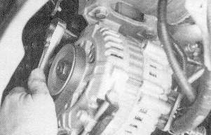
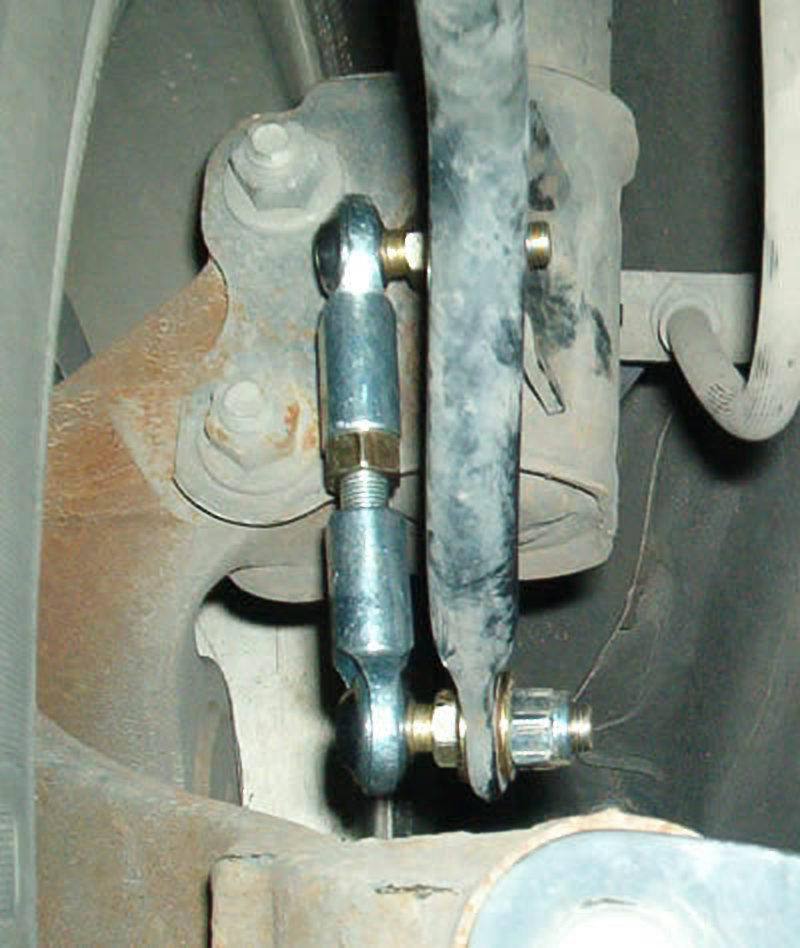
Step 8:  Loosen the bolt on the alternator belt tension rod .

  1. On the bottom of the alternator, you will see a bolt and a metal device that it is in. Loosen the nut that is holding the bolt. (the nut facing the right tire).

Step 9:  Loosen the alternator pivot bolts .

  1. There are two of these bolts, and they are at the top of the alternator (one on each side, in line with each other).

Step 10:  Relax the tension on the alternator belt.

  1. Loosen the alternator belt adjuster and squeeze the belt together to move the alternator toward the engine.
  2. Note: the alternator may be hard to move, just keep working it, until it loosens

Step 11:  Remove the alternator belt.

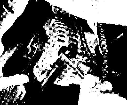
Step 12:  Unplug the large connector .

  1. Press in on the tab on the connector and pull it out of the alternator

Step 13:  Disconnect the wires from the rear of the alternator .

  1. Unscrew the nuts that attach the wires, and pull the wires off their studs.
  2. Watch for falling debris in your eyes.

Step 14:  Free the alternator harness clamp .

  1. Remove the 8 mm bolt that attaches the clamp to the rear of the alternator.

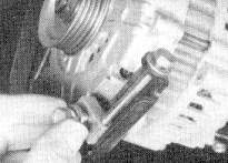
Step 15:  Remove the adjuster bracket from the alternator

  1. Unscrew the bolt that attaches the adjuster rod and bracket to the bottom of the alternator.

Step 16:  Remove the alternator pivot bolts.

  1. There is a second bolt at the rear of the alternator (identical to the easier viewed one), directly in line with the front one.
  2. Remove both, securing the alternator with your hand so it doesn’t fall on you.

Step 17:  Remove the alternator

  1. I had trouble getting mine out and had to push back and forth until it finally came loose.
  2. At this time you can remove and replace the power steering belt. The tensioner is in view.

Step 18:  Install the new alternator .

  1. Install the bolts above the alternator, finger tight at first.
  2. Do not tighten these until the alternator belt tension has been adjusted.

Step 19:  Attach the lower adjuster bracket .

  1. Screw in the bolt that attaches the adjuster rod and bracket to the alternator

Step 20:  Connect the large wire to the alternator .

  1. It mounts on the upper stud.

Step 21:  Connect the small wire to the rear of the alternator .

  1. The small wire mounts on the lower stud.

Step 22:  Attach the alternator harness clamp.

Step 23:  Plug in the large connector

  1. Press the connector into the alternator until the tab locks it in place.

Step 24:  Install and tighten the alternator belt.

  1. Tighten the adjuster nut until you can deflect the belt ¼ – ½ inch midway between the pulleys.

Step 25:  Tighten the pivot bolts.

  1. again, the bolts above the alternator.

Step 26:  Install the air conditioning belt.

  1. assure that the grooves and ridges in belt match up with the grooves on the pulley.

Step 27:  Install the splash shield on the right wheel well.

Step 28:  Install the lower splash shield .

Step 29:  Lower the car .

Step 30:  Adjust the air conditioning belt .

  1. from the top, turn adjuster bolt clockwise until you can push the belt inward about ¼ inch.
  2. Again, this adjusting nut is 12 mm just above the air conditioning idler pulley.

Step 31:  Tighten the pulley bolt.

  1. this locks the tensioner and prevents it from loosening.

Step 32:  Connect the battery.

  1. connect the positive first.

Loading

Member Credit: Matt Blehm

Please note that this post is for reference and documentation purposes ONLY. Matt Blehm no longer offers these products or services. Products were available from 2003 to around 2009.

Lower Tie Bar: Now for 89-2003 Maxima, and B14 200SX/Sentra!

This part is designed to tie the front suspension together to provide sharper steering response and better handling overall.

These parts are powdercoated black. If you would like other colors, I can do it, but buyer will be responsible for additional charges.

Stage I

This is a bar that ties together the bolts on the front lower control arm gussets, providing sharper steering response and less chassis flex in corners. Handling improvements are very similar to installing a strut tower brace, which you can also add on the top of the suspension to tie the front end together really well!

The only drawback is that you lose a bit of ground clearance- but since it sits between the front wheels, the only time you might have a problem is when driving over extremely uneven surfaces. I have had the Stage II bar (see below) on my car for six months now and have only scraped it three times- all of which could have been prevented had I been paying more attention while going over extremely rough roads.

The price for the Stage I lower tie bar is $65, plus shipping- a VERY worthwhile and affordable mod!

Stage II

This one is a bit more complex. It bolts onto an additional frame mount behind the control arms to provide more strength and reduce chassis flex even more. You don’t lose any more ground clearance, but you do gain several more steps up the ladder in the handling department.

For 3rd gens, this requires a small amount of grinding on the left side gusset to fit, but does not alter or weaken the structure of the car at all–you simply have to enlarge one hole by about 2mm for one of the mounting points to fit properly. For 4th and 5th gens, this is a simple 15 minute install (assuming you have air tools and a jack).

Current fittments WILL Clear all aftermarket Y-pipes (Warpspeed Performance, Cattman, Stillen), but will NOT clear the Cattman headers on the 4th gen. I’m working with a customer in redesigning the 4th gen bar so that it will fit. If you have these headers or plan to purchase them, stay tuned and I’ll have a design that fits.

Price on the Stage II Lower Tie Bar is $175, plus shipping.

4th Gen Stage II Lower Tie Bar

5th Gen Stage II Lower Tie Bar

B14 Stage II Lower Tie Bar

Rear Strut Tower Brace: For 89-94 Maxima

Exactly what it says it is!! You’ve seen them on 4th gens, you’ve seen them on Sentras, you’ve seen them on every car BUT a 3rd gen! I argued for years that they wouldn’t do anything, but I decided to build one not long ago, and boy was I wrong!!

Pricing: $100 each, plus shipping. (This isn’t your $29 ebay fstb!!)

Rear Parallel Link Replacement Kit: For 89-94 Maxima

Another crazy mod for your 3rd Gen!

This is a mod only for the hardcore guys out there. It’s rough and it’s tough, and it’ll (almost) hang with a Miata in the twisties!! These do add some road noise over gravel roads at low speeds, but the ride quality doesn’t change between these and stock bushings. I notice no additional highway noise, and the ride is MUCH smoother than with my worn bushings in the rear.

This kit also allows you to adjust Camber AND Caster in the back!

This kit replaces both rear parallel links and radius rods on both sides, for a total of 6 bars, 12 Heim joints, and all the bushings you’ll need to install them properly.

I can get the tubes in zinc plated (pictured), or black. I can powdercoat them just about any color you want as well, so contact me if you’d like some other colors.

This kit is priced at a VERY reasonable $375 for the set. Again, the second picture shows just one side, but you do get both. The joints used in this kit are very high quality– they have teflon lining injected into them so they should never need lubricating and will never rattle like the cheap ones.

Okay, so what is it exactly? I’ll let the pictures speak for themselves:

Rear Sway Bar Links:

89-94 Maxima

Tired of your rear sway bar links breaking, clanking, and rattling? Here’s the solution! These are made from all high-strength materials. 1/2″ aluminum bottom plate, grade 8 mounting hardware, and the heim joint on top is permanently lubed with kevlar/teflon injected into the joint. Guaranteed not to break! Overkill to say the least, but you don’t want these to break AGAIN, do you?

Price for the Maxima kit is $45 + shipping–includes all hardware pictured for both sides of the car.

1st Generation Altima

I have some Energy Suspension Sway Bar Bushings on the way as well and will be selling these as complete front and rear kit when they come in. Final pricing will be determined later.

Loading

Member Credit: Bryan Tisc

All of the third generation Maximas feature many standard options.  The U.S. third generation Maxima came in two models, the SE and GXE.  The SE, targeted a sporty end of the market while the GXE emphasized more luxury features.  The SE features stiffer springs, sway bars, struts, strut mounts, and bushings.  Also, from 1992 – 1994, the SE had a high output DOHC engine with variable timing control.  Here are some standard features that both models share.

  • Standard allow wheels- 6.5 inch on the SE, 6 inch on the GXE
  • Four wheel independent suspension
  • Power windows, locks
  • Power/Comfort button for automatic transmissions
  • Cruise Control
  • Air conditioning
  • Standard security system (ignition disable, doors, trunk, hood- no shock sensor)
  • Rear window defrost

SE vs. GXE:

  • Tighter suspension, thicker sway bars on SE, not GXE
  • Dual tipped exhausts on SE versus a single tip on the GXE
  • Black rear view mirrors on SE versus body colored Mirrors on GXE
  • Rear disk brakes on SE, rear drums on the GXE
  • 5 speed manual available on SE, automatic-only on GXE
  • 6.5 inch rims on SE, 6 inch rims on GXE
  • Driving lights standard on SE’s, no driving lights on GXE
  • Spoiler standard on SE, no spoiler standard on GXE
  • White gauges standard on SE, black guages on the GXE with reduced bolding.
  • Sport leather steering wheel on SE, standard steering wheel on GXE
  • DOHC high output engine on 92 – 94 SE models, SOHC on all GXE’s
  • standard exterior door locks on SE, GXE’s standard with keyless entry

1989-1991 SE specific

  • VG30E SOHC engine generating 160 hp and 182 ft lbs of torque.
  • Standard Moonroof
  • Standard Bose Radio
  • Black rear lenses
  • Split front grill with a small “Nissan” sign
  • Standard with H rated tires
  • lever to open trunk left of driver’s seat

1989 – 1991 SE & GXE specific

  • hinged door under radio
  • all speedometers at 1 25 mph
  • all tachometers redline at 6000 rmps
  • split grille with Nissan name

1991 changes   

  • New Bose stereo face design started
  • chromed wheels started
  • Extended mirrors on SE models

1992 changes

  • An extendable bin under the radio
  • OD light is different in that it is spelled out instead of a separate light on the right
  • SE’s now have a button to open the trunk instead of the lever.
  • stronger transmission for VG30E
  • plastic bezel around the radio/climate control changed in that there are no screws above the radio to remove.
  • new steering wheels for each model.
  • New mesh grille with Nissan logo.
  • Black rear gone, SE’s have read rear lenses with a slight lens design change.

1992-1994 SE specific

  • VE30DE DOHC engine generating 190 hp and 190 ft lbs of torque
  • VLSD Viscous Limited Slip Differential) – if last letter on transmission code = V.
  • Red rear end
  • Meshed front grill with Nissan logo in center.
  • Heated side mirrors
  • Came standard with V rated tires (up to 149 mph)
  • speedometer to 145 mph, tachometer to 6700 rpm redline

Loading

Member Credit: shift_ice

Over time the brake system can take on air as the effectiveness of the brake fluid decreases with age. Air can also enter the system from a leaky brake hose, a bad connection on the brake caliper, during any maintenance when a brake line is removed, or if the fluid reservoir is allowed to run dry.

Air in the line makes the brake pedal feel mushy, and bleeding the brakes is the solution to that embarrassing mushy pedal feel. While we’re on the topic, if you’re not happy with the factory brake feel even after the system is properly bled, replacing the factory brake lines with more sturdy steel braided lines can greatly increase pedal firmness and brake feel.

Ttools/Supplies:

  • Lug wrench
  • 14mm wrench
  • Jack
  • Clear Jar
  • Small hose at least 6″ long. Approximate diameter of bleed valve. The tighter fit the better. Auto parts store should have small vacuum hose that will work.
  • Fresh jar of brake fluid (do not use a previously opened container since brake fluid takes on moisture over time.
  • An assistant or speed bleeders.

INSTRUCTIONS:

1. Place the car on level ground, chuck the rear wheels, and make sure car in park (or in gear if a manual). Make sure parking brake ISN’T on. If you have ABS, remove the ABS fuse.

2. Pump the brakes multiple times to release any residual vacuum in the lines.

3. Remove the brake fluid reservoir cap and fill the reservoir with fresh brake fluid. Check this level often as you bleed the brakes. Never let it get too low because if it gets empty it introduces air back into the brake system and you have to start all over!

Bleed the brakes in the following order:

1. Passenger rear
2. Driver front
3. Driver rear
4. Passenger front
4. Remove the rubber boot on top of the bleeder screw. Attach a hose to the bleed screw and insert the end of the hose into a clear jar that is partially filled with brake fluid.

The bleed screw with the rubber boot still on:

Bleed screw

Hose attached to bleed screw:

Hose attached to caliper bleeder screw


5. Have your girlfriend press firmly on the brake (you’re killing time reading this on the internet so you obviously have one…right?). While the brake is depressed, loosen the bleed screw. If your girlfriend freaks out at this point because the pedal just fell to the floor, throw an empty beer can at her and tell her to quiet down. Or, if you’re not much for the single life, you can be the nice guy. “Honey, that it is completely normal. I just loosened the bleeder screw which allows the brake pressure to escape…oh, and I sure like those new strappy shoes of yours.” Totally your call on this one.

Anyway, back on topic. When you loosen the bleed screw with the brake depressed, you will see brake fluid flow through the hose and into the jar. Watch the tip of the hose for air bubbles – this is a sign that air is in the system. When the flow of fluid stops, tighten the bleed screw and tell your girlfriend (assuming she’s still there) to release the brake. Repeat this process (press brake, loosen bleeder, check for bubbles, close bleeder, release brake) until there are no air bubbles released, only fluid.

If you mouthed off above and lost your assistant, don’t worry, this step can also be done alone if you buy a set of speed bleeders.

6. Check the brake fluid level in the reservoir and top off as needed. Take care not to overfill or spill because brake fluid is very hard on paint. As mentioned above, never let the reservoir get empty or it will introduce air into the system and you’ll have to start over. And let’s be honest, this job is barely enough fun to do once.
7. Repeat steps 4 -6 at each wheel in the order outlined above. For the front brakes, if you’re feeling lazy you can get away with not removing the wheels at all by turning the tires toward the brake you want to work on. It takes a skinny arm or a strange angle to get a wrench on the bleed screw, but it can be done.

A lazy man bleeding the front brake:

Bleeding the front brakes with the wheels on


8. When complete, do yourself a favor and double check that every bleed screw is tight. Remember, a loose bleed screw means no brake pressure and brake fluid spraying everywhere like a garden hose. And hey, that’s no fun. Well, unless you’re the lucky onlooker.

Seriously though, test the brakes on a flat surface before running out and terrorizing the neighborhood.

Loading

Member Credit: shift_ice

There are many rotor and brake pad options for the Maxima. Check out the brake choice how-to if you’re having problems deciding. In this how-to, I install Hawk HPS pads and Brembo blank rotors, though the process will be the same for any OEM replacements.

The new equipment:

Tools/Supplies:

  • Lug wrench
  • Hammer – the bigger the better!
  • Socket wrench
  • 14mm, 17mm & 19mm sockets
  • Rotors
  • Brake Pads
  • Disc Brake Caliper compressor (aka caliper spreader) tool (available on loan from many autopart stores)
  • Hanger
  • Wire Brush
  • Piece of scrap wood (optional, useful if rotor is rusted on)
  • Brake grease (typically available at the front counter of most autopart stores)
  • Brake Cleaner
  • Jack
  • Jack stands
  • Wheel chuck
  • Old rag
  • Torque wrench
  • Turkey baster (optional, to remove extra brake fluid from reservoir)

INSTRUCTIONS:

1. Place car on level ground. This is very important since you’re removing the brakes! Chuck the rear wheels and pull parking brake while doing the front wheels. Jack up the front of the car using the jack point outlined in the manual.
2. Remove wheel using lug wrench


3. Remove the 3 17mm bolts that attach the caliper. There are two on top and one toward the bottom of the caliper bracket.

NOTE: Do NOT remove the bolt that connects the brake line to the caliper. This will introduce air into the brake system and you will have to bleed the brakes to get the air out. The brakes will be very spongy until this is resolved.

So keep the brake line connected and hang the caliper to avoid strain on the line as described in the next step.

Removing the top brake caliper bolt:


4. The caliper should easily slide right off the rotor after removing the above 3 bolts. Hang the caliper with an old coat hanger from the top of the spring. Never let the caliper hang from the brake line – it can damage the brake line and cause a leak.

Caliper hanging from hanger:


5. Remove the two 19mm bolts on the back of the caliper mounting bracket.

Two bolts circled in red:


6. NOTE: This step and any steps below relating to the rotor, only apply if you’re replacing the rotors as well. If the brake pedal pulsates when you press on the brake, you might consider replacing the rotors as well. This is typically noticable when braking harder at faster speeds such as when exiting the highway on an offramp.

Remove the rotor. Depending on the age of the vehicle and climate, the rotor may be rusted on. My Maxima was only 3 years old and my rotor was rusted on tight. To remove a rusted rotor there are a number of options:
Apply a liberal amount of WD-40 to back of the rotor and inside the lug holes on the front. Allow to soak. After a few minutes of soaking, use a large hammer and strike the back of the rotor in various locations to help dislodge it. If you are removing the rotor so it can be machined at a shop, be sure to use a piece of old scrap wood so you don’t damage the back of the rotor by striking it directly with a hammer. I started with a rubber mallet but eventually had to use a large steel hammer to knock my rotor loose.
Alternatively, you can use the holes on the caliper mounting bracket to help push the rotor off. This requires a 4″ long, 1/2″ wide bolt with a matching washer and nut.

7. Open brake fluid reservoir and wrap an old rag around it to catch any spill.
8. Compress the caliper pistion using a C-clamp or Caliper piston compressor tool. The C-clamp method only works on the front brakes since the rear piston must be twisted as it is compressed (the piston caliper tool naturally does this). While there are a variety of piston compressor tools, the general premise is to place the flat metal plate inside the caliper and twist the bolt until the strike plate (which rests against the piston) presses the piston back into the caliper. See the picture below. If you choose to use a C-clamp, place the old pad against the caliper piston so the c-clamp doesn’t press directly against the piston and mar the metal.

NOTE: As you compress the piston, the brake fluid level will rise. Keep an eye on the brake fluid level and siphon out any extra fluid or cleanup any spill that occurs. I recommend siphoning out some of the fluid since brake fluid is hard on paint.

Brake caliper compression tool kit:


9. Note the orientation of the pads. It’s also good idea to do one wheel at a time so you can always reference the other wheel if you have any question on how to orient the pads on reinstall.

Only one of the two bolts that need removed are visible here:


10. Remove the two 19mm caliper mounting bracket bolts (the cradle that holds the pads).

11. If the old rotor was stuck, use a wire brush to clean the hub face. Optionally, you can apply a small amount of grease to the hub face to keep the new rotor from sticking sometime down the road.
12. Before installing the new rotor, it’s important to clean it off with rubbing alcohol and brake cleaner or rubbing alcohol. Rotors are shipped from the factory with a protective coating to keep them from rusting before sale. Use a liberal amount of brake cleaner and give it a good scrub until it no longer feels like it has a film on it. Once clean, install the new rotor by sliding it over the lugs.

New rotor installed:


13. Remove the old brake pads from the caliper mounting bracket and clean the shims and hardware thoroughly with brake cleanup. Use a clean rag to scrub off deposits. Make sure this hardware is smooth and clean. The pads slide back and forth in this hardware so it’s important to make sure the path is smooth as possible. Once clean, dry them off.

14. Apply grease to all the touch points in the channel where the pads sit. Apply a liberal amount of grease on the back of the brake pads and reinstall the shims. Apply grease to the points on the caliper mounting hardware where the pad will sit.

Apply grease to the following points on the brake pad. This is the back pad so the shim is smaller. Apply a liberal amount of grease to the back of the pad wherever the shim and the pad meet.

Apply grease to the following areas on the brake pad

15. Reinstall caliper mounting bracket and torque bolts to 53-72 ft. lbs. Insert pads back into caliper mounting bracket and slide caliper over the pads.

16. Reattach caliper to caliper mounting bracket and tighten caliper mounting bolts to 16-23 ft lbs.

Completed job:

17. Check brake fluid level. Add fluid from a brand new bottle of brake fluid as needed. It’s important not to use brake fluid that has already been opened because brake fluid soaks up moisture overtime reducing its effectiveness.

18. Reinstall wheel, remove wheel chucks, and lower car.

19. IMPORTANT: You must bed the brake pads after installation. This is very important to help avoid squeaking down the road. The specific bedding procedure is typically provided with the brake pads, but the general rule is to drive around 45 and brake hard, releasing the brake right before coming to a stop. Repeat this process 4 or 5 times.

20. While not required, it’s a good idea to bleed the brakes after doing a brake job.

21. The pictures above are for the front brakes, but doing the back is just the same with a couple minor differences:

Remove the 14mm bolt holding the mount for the emergency brake cable to get the upper part of the caliper off.
The lower piece of caliper has 17mm bolts.

The piston must be turned clockwise to be compressed. Make sure the end of the caliper compressor is inserted properly into the grooves in the piston so the tool actually twists the piston as it compresses.

Hook the emergency brake cable back onto the spring mechanism before reinstalling the upper caliper piece. It’s hard to hook up after the caliper is assembled.

To get the rear caliper back over the rotor, you must turn the cylinder so the nub lines up with the groove it slides into.

Edit: Here’s a few more notes submitted from reader ajahearn:
Some vented rotors are directional so people need to pay attention to the one to install.
Slotted/drilled/dimpled/etc rotors are supposed to be non-directional but some manufacturers want you to install them such that the first dimple/part of the slot/etc that reaches the pad needs to be at the top with the idea that any grabbing will pull the pads inward toward the hub and not force them upward away from the hub.

The caliper should never be left hanging from the brake line – it should always be supported by a hanger or bungy cord.

For the rear piston, the boot may start to bind and make it harder to compress/rotate. To resolve, occasionally back off (counter clockwise) to get the boot to straighten and then start again. And opening the bleed valve makes it considerably easier to turn the piston back in. Of course you need to have a hose to prevent the fluid from spraying

Loading