
Member Credit: René Saran
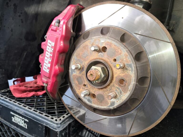
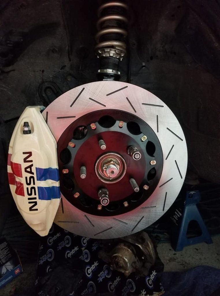
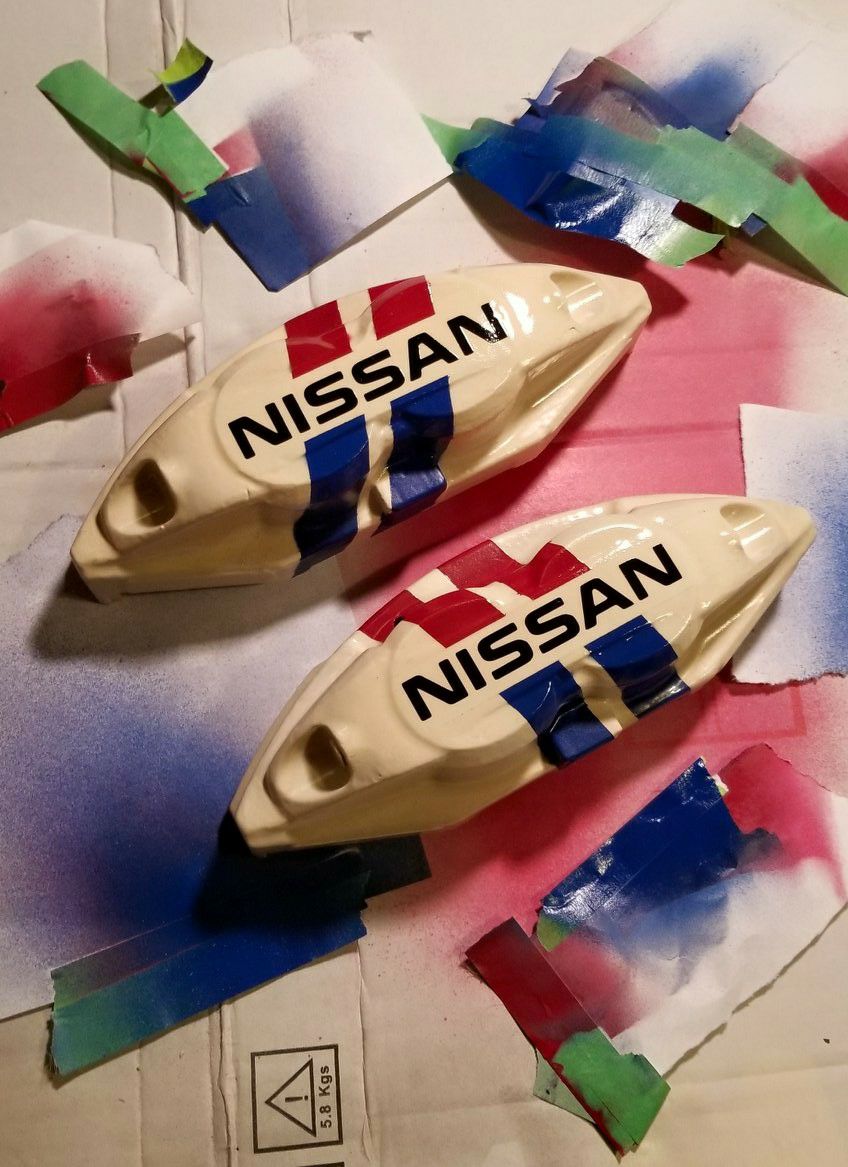
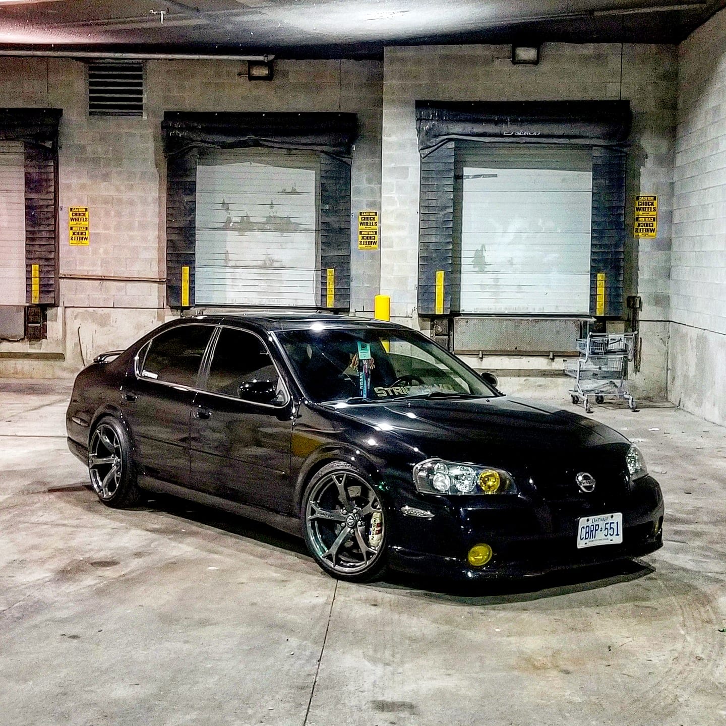
Custom painted front Akebono Big Brake Brake (BBK) calipers with Z1 2-piece rotors. These are using a custom bracket made to fit the caliper on 2000-2003 Nissan Maxima.

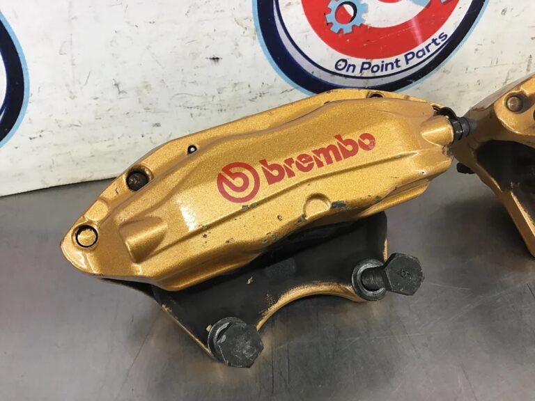
Installation of Infiniti G35 2004 / Nissan 350Z 2003-2009 4-Piston calipers on 1995-2008 Nissan Maxima (also fits Infiniti I35, Altima SE-R). They are 100% direct bolt-on with no custom brackets needed. There is no pad overhang. Overall, solid cost efficient setup.
This setup using the 6thgen 12.6″ which are easy to find and low cost. Additionally, no need for any custom brackets which is awesome. It’s almost like factory OEM.


Photos and Video below courtesy of Kirill Savin


This is the reason you need the guides. Otherwise pads will shift like the below:


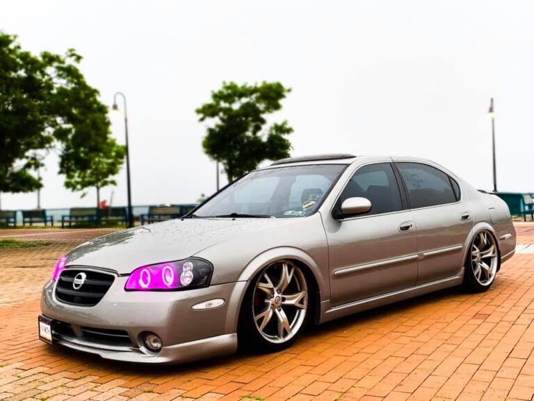
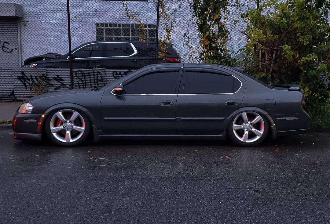
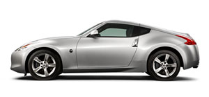
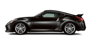
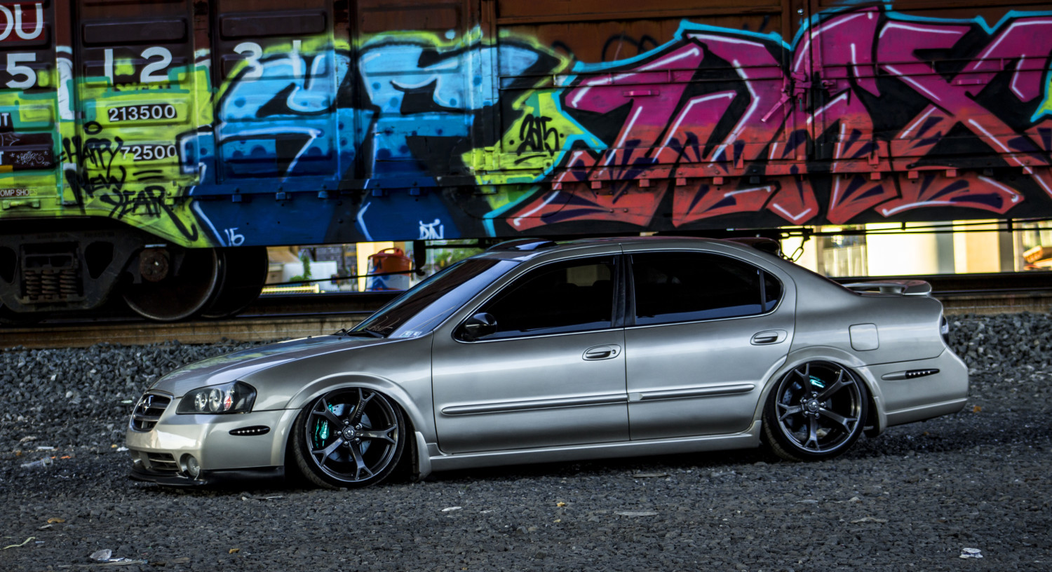
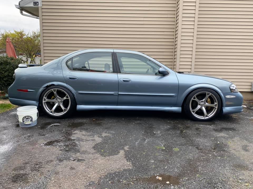
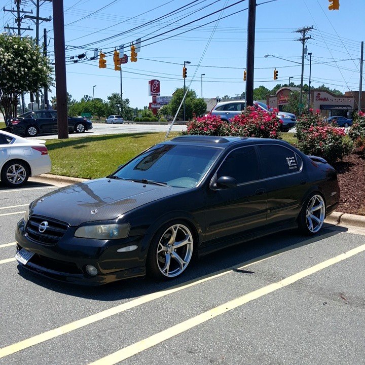
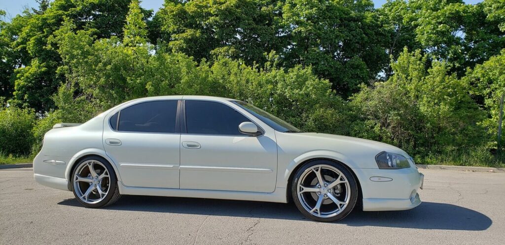
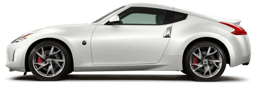
Below are the factory rim and tire specifications for Nissan 350z/370z models which are commonly installed on the 5thgen Nissan Maxima.
Front Wheels: 18×8 +30MM
Front Tires: 225/45/18
Weight: 24.4lbs
Rear Wheels: 18×8.5 +33MM
Rear Wheels: 245/45/18
Weight: 25.8lbs

Front Wheels: 18×8 +43MM
Front Tires: 225/50/18
Weight:
Rear Wheels: 18×9 +15MM
Rear Wheels: 245/45/18
Weight:

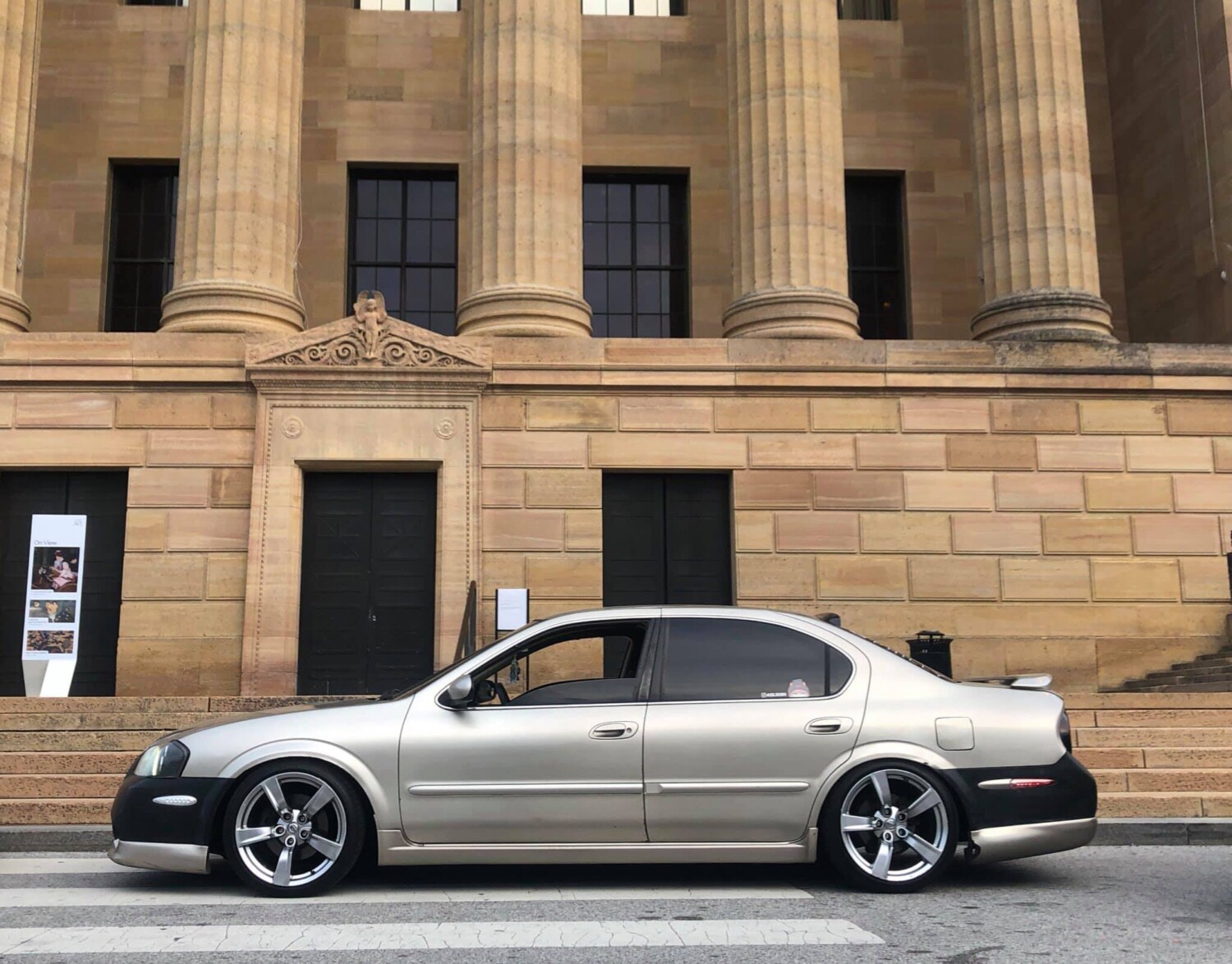
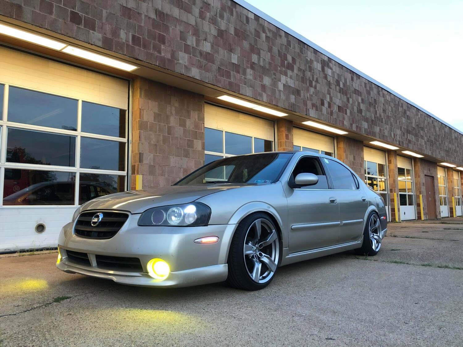
Front Wheels: 19×9 +47MM
Front Tires: 245/40/19
Weight:
Rear Wheels: 19×10 +30MM
Rear Wheels: 275/35/19
Weight:
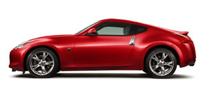

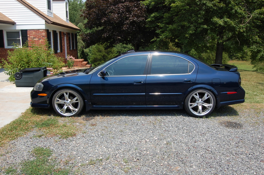
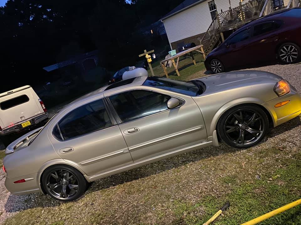
Front Wheels: 19×9.5 +40MM
Front Tires: 245/40/19
Weight:
Rear Wheels: 19×10.5 +23MM
Rear Wheels: 285/35/19
Weight:
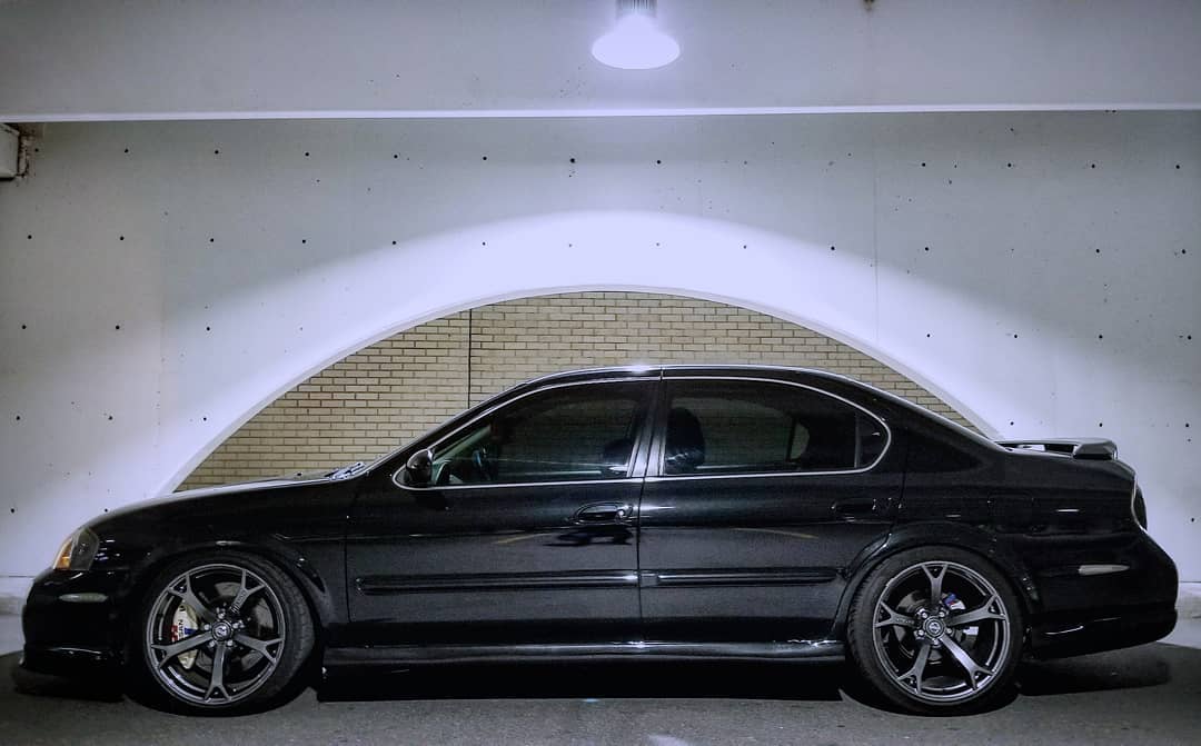

Community Member Credit: Frank / motorvate.ca
When the steering wheel is turned quite a bit (like in a parking lot) you hear a crunk-crunk-crunk.
The upper strut bearing grease dries out which makes the bearing stiffer and more difficult to turn. When this happens, as you turn the steering wheel the bearing does not move, but the front spring “winds up” until there is enough force to overcome the stiff bearing. Then you hear the crunk as the spring unwinds. The whole process repeats over as you turn the steering wheel.
Solution:
Remove the upper strut bearing, and REPLACE them ($25 each) with new ones. Repacking the grease is tricky, if you don’t pick the correct grease, you will have the problem return in 8-12 months. (I did)
Remove the 2 large nuts and bolts that join the strut, to the steering knuckle.

Not shown: Remove three nuts from the top of the strut. Remove the clip that holds the hydraulic brake line, and free brake line from strut. Remove the 10mm bolt that hold the ABS sensor cable to
the strut.

Attach the spring compressor. Tighten the spring compressor finger tight.

Place the strut in a vice. (carefully, don’t clamp down too much) Tighten the spring compressor until the spring is just a little loose. Remove the single strut nut. This is very easy if you have air tools, but if you do not, then you will need to hold the shaft, and remove the nut.
Remove the dark orange noise insulator, remove the black rubber insulator
Remove the lower part of the black rubber insulator.

The clean spot you see in the center is the place where the strut bearing sits. (Notice all the sand in the upper spring perch. Two out of three drainage holes were blocked with road sand from 5 years of Canadian winters. Make sure to clean out any debris, to allow proper water drainage.

Believe it or not, this dark colored tiny PLASTIC piece is the strut bearing.

The upper strut bearing
The inside of the upper strut bearing.

Do not try to re-grease the bearings. I did, and it lasted 10 months, and the same noise came back. Spend the $40, and it is fixed for the life of the car.

Above: This is a close up of the dark coloured bearing end cups, and the white ring.
To assemble, just reverse the steps. Make sure you tighten all nuts and bolts to the factory specification which are found in the Nissan Service Manual. Since your entire front suspension has been removed, you must get your alignment done, if you want your tires to last.
Summary:
With the new strut bearings, it turns smoothly, and the crunk-crunk-crunk sound is gone because the spring on the strut will not be “winding up”.
Total cost was $40 for the new upper strut bearings. My alignment was a little more at $80, but now my front camber, and toe are in spec.

Community Member Credit: Frank / motorvate.ca
When I would tell my friends that I had replaced my brake pads and brake shoes they were shocked. They would ask me “Why would you do that?”, “Do you know what you are doing?”. Some would tell me “I would never do that, what if you did something wrong? You should not touch with your brakes. Leave them for a mechanic” However, as you will soon see, changing your front brake pads are really quite simple. I will show a step by step pictorial, from when I changed my front brake pads and rotors on my 95 Maxima.
Raise the front wheels, support with jack stands, and remove the front wheel. Always work safe, and use proper jack stands that are in excellent working order. You life may depend on it.

Here is a close up of the caliper and rotor.

If you look in the “inspection window” of the caliper you can see how thick your pads are. Here you can only see the inner (shown on left side of photo), as the outer pad is hidden in the shadow.

This is a close up of the upper part of the caliper. Here you can clearly see the inner (left) pad, rotor, and the outer (right) pad. Notice the outer pad is quite thin, compared to the inner pad? More on this later.

Remove the 14mm bolt from the top of the caliper.

Remove the 14mm bolt from the bottom of the caliper.

Remove the caliper. It should slide off, with little force. Using a some wire, hang up the caliper from the spring perch, checking that the caliper is not hanging by the rubber brake hose. Right:

Here is the view of the caliper piston and piston seal.

The brake pads, shims, and upper and lower are shown here.

Remove the brake pads by sliding them out, with the shims. Then remove the thin metal clips that are on the top and bottom of the caliper. They are there to enable the brake pads to easily slide on them, and they also have clips that holds the pad, so they don’t rattle over bumps. The shims, and the clips are part of a “brake hardware kit” Nissan recommends that they are replaced when the pads are replaced, but I replace mine only when the the shims show moderate corrosion. (We use A LOT of salt in Canada during the winter)

With the brake pads, and upper/lower clips removed. NOTE: You can see the caliper resting on the rotor. This is an example of what not to do. If the caliper slips and falls, the brake hose will stop it from falling, but the hose will be strained, and it may leak. To prevent this, hang it up with some small wire from the front spring. Right:

Remove the two 17mm bolts that hold the “torque member” (hey, that is what Nissan calls it) Remove the torque member.

The rotor should slide right off the hub. If not use a 2×4 to tap it, until it is unstuck from the hub. Right:

With the rotor removed, you can see the hub. NOTE: the silver stuff on the hub is anti-seize compound. This should prevent the rotor from rusting to the hub.

Summary
At this point the brake pads, torque member, and rotor have been removed. It is now time to clean up the brake hardware, remove the old grease and re-grease the caliper locating pins. Click Front Brake Reconditioning, to continue.
So far, we have removed the front brake pads, shims, caliper, torque member, and rotor. It is now time to clean up the brake components, clips, shims, and re-grease the caliper sliding pins.
Scrape any loose rust of the area shown above. You want to make sure that clips fit all the way to the bottom. If not, your brake pads may get “hung up” on the clips, and this could lead to your brake pads dragging just a little bit, causing them to wear unevenly.

This is the brush that I like to use. It has stainless steel bristles and it removes any rust very fast. I purchased it at Princess Auto, for about $6.

To remove the pin that the caliper slides on as the brake pads wear, you can gently pull them out. If these stick in any way, the caliper will not be able to slide to (brakes on) are away (brakes off) from the from the rotor. This can lead to the brake pad dragging, and this causes the pad to wear very rapidly. In one case I saw a car with the rotor glowing red!

On the top of the picture is the upper pin (as located on the torque member), the other pin is the lower pin. You can see that the grease here is in fair condition.

Use the small wire brush to clean around the torque member where the brake pad clips, and rubber caliper pin boots are. Clean out all the old grease from where the caliper pin slides in the torque member. Right:

I turn the caliper pin boots inside out to remove all of the old grease. The grease shown here is not in very good shape.

Before (right) and after (left) pictures of the clips during cleaning.

A close up of the freshly cleaned pad clip.

Place a small amount of grease (high temperature synthetic) on the pin, and in the hole. Push in the pin all the way to expel excess grease. When you pull the pin out, if it is a little stuck, then you have too much grease. Pull out the pin, and wipe off some grease and try again. If you have too much grease, air can not get in behind the pin as you try to pull it out and it is a little “hydro locked” You want these pins to slide very easy.

Place a little grease (again, high temperature synthetic) in the boot, place the boot over the pin, and put the pin in the torque member. Push the pin in all the way, and lift the boot so that any trapped air, or excessive grease can escape. Check again to make sure the pins slide easy.

Brake pad shim, with a little corrosion.

Close up of the corrosion. The next time I will purchase the brake hardware kit, and replace the shims. I don’t want anything that can compress slightly under hard braking between my caliper, and my brake pads. (like corrosion)

Summary
At this point the brake pads, torque member, and rotor have been removed. The caliper sliding pins have been re-greased, the torque member clip attachment area has been scraped and cleaned, as well as the brake hardware (shims & clips) have been cleaned. The caliper pins, rubber boots, and the torque member items have all been assembled. Click on Front Brake Assembly to continue.
Front Brakes – Assembly Update So far, we have removed the front brake pads, shims, caliper, torque member, and rotor. We have also cleaned up the brake components, clips, shims, and re-grease the caliper sliding pins.
Now it is time to assemble.
You MUST remove the protective coating that are on the new rotors. It is like a thin coating of thick grease. I like to use isopropanol alcohol as it cuts the grease quickly, and dries without any residue. Keep turning the rag until it wipes clean. Do not use gasoline as a cleaner, it is just too flammable.

Place the cleaned rotor on the hub. I put a little dab anti-seize on the outside edge of the hub. This is to ensure that I won’t have any problems getting the rotor off down the road. Notice the caliper is resting on the rotor’s dust shield. It really should be hanging up to ensure the brake hose does not get tugged, and develop a leak. Do as I say, not as I do 😉

I like to use a little anti-seize compound to make disassembly easier down the road. These are the 17mm bolts that hold the torque member.

Bolt on the torque member, attach the pad clips. Note: The single wheel lug is to hold the rotor flat against the hub.

Slide in the brake pads. Make sure your hands are free of grease and oil.

Put on the pad shims

Open the cap to your master cylinder to let the air out, as we push back the caliper piston. You should not remove it, just untwist it. Brake fluid likes to absorb moisture, and this can cause corrosion and a lower boiling point of the brake fluid. Right:

Carefully and very slowly push the piston back. Notice that the C-clamp is strait. If the clamp is crooked, you may cock the piston in the caliper. It does not take a lot of pressure to push it back. If you need a lot of force to push it back, your piston may be cocked sideways, or partly seized.

The piston is fully pushed in.

You can see how much the brake fluid level rises for just one side. Never let anyone at a “Rapid Lube” type place “top up” your brake fluid. It will just overflow the master cylinder when the next brake job is done.

Slide on the caliper, and tighten the bolts
Make sure the caliper pins are positioned as shown. The pins have a flat spot, and the casting of the caliper has a “bump”. Make the pin is sitting flat, and not on the raised part of the caliper.

Remove the wheel lug, and bolt on the tires. Time for a test drive.

Here is why I had to do my brakes. The outboard pad on the driver’s side was worn down to the “noise maker” I think this was due to too much grease (and not enough air) in the caliper pins, which would hold the pad against the rotor just a little. Over time it wore the pad down. All other pads wore the same. My fault, but you get to learn from my mistakes.

Here is what happens to your rotor when you use them a lot. You are looking at thermal stress cracks on my old rotors. This is caused by the rapid increase in temperature under hard braking. Over time the disk can fracture. I was not going to wait for that, so I spent $65 per rotor at Canadian Tire. (Nissan rotors are $90)

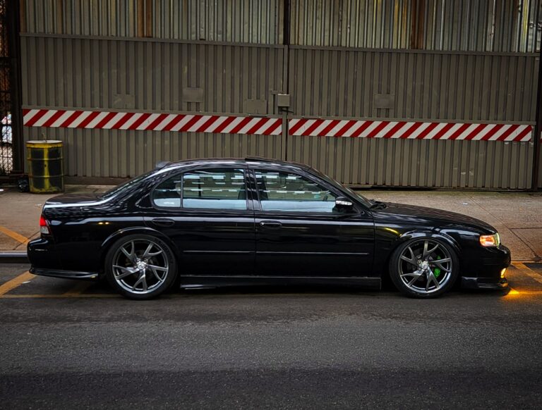
Credit: Eddy
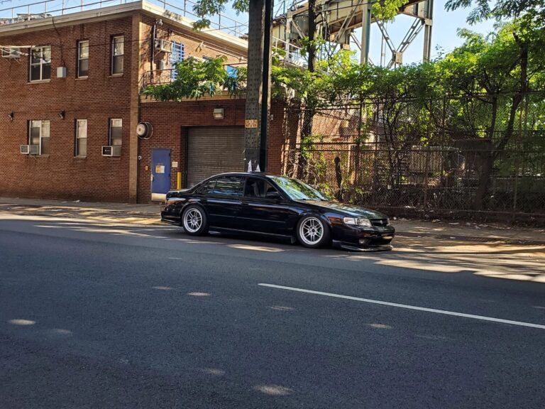
Always been a fan of Rays Engineering wheels on my Nissan Maxima’s. Below are the specs for my 1998 Nissan Maxima. My setup is full set of front wheels.


Member Credit: 95BLKMAX
I wanted bigger brakes, but I didnt want to spend a fortune (as much as one would spend, say for a Z32 upgrade, or the 6th gen rotors with Z32 calipers, etc…) for just front brakes. Plus I dont autoX, I just do alot of highway spirited driving; so I wanted a beefier setup that wouldnt break the bank.
Parts / Cost:
SPECS – (Per 1995 FSM and 2003 FSM)
4th gen Rotors (mm/ inches)
280×22/ 11.02×0.87
5.5 gen Rotors (mm/ inches)
296×24/ 11.65×0.94
4th gen Caliper Pot (mm/ inches)
57.2/ 2.252
5.5 gen Caliper Pot (mm/ inches)
57.2/ 2.252

HOW TO- (I write this assuming you already know how to do a brake job, this how to made with attention to the work specifically related to the conversion process of being able to install these bigger brakes)-
Remove wheels, calipers (disconnect the lines from them but have a bottle near, they will leak alot of fluid), caliper mounting brackets and pads
Have this ubber drill bit…

It cost me $35 locally at a “nothing but nuts and bolts- specialized hardware store (Mitchell Supply Company) also 4 of these Metric bolts with lock washers (stock 4th gen on left, new 5.5gen on right)…

I bought them so long ago I dont recall the specs, so just go to the hardware store with the caliper mounting bracket for thme to check * With the Ubber drill bit, drill out the two holes on the hub. Try your best to keep it straight. Go slow with the bit at first because if it gets caught up, the drill WILL fling around and it could cause bodily harm depending of how strong of a drill you have. Once it started boring the hole out just go downtown on them. They should look like this afterwards…
Make a few cuts along the shield’s overlap up to the vertical part and with pliers bend the overlap up to vertical. The 5.5gen rotors wont fit otherwise…

Now with that done, the installation is the exact same as a normal brake job, only that you’re using the 5.5 gen parts. Hook up the lines and you will have to bleed ALL 4 calipers. At least with me, I let so much fluid drain that air got into the master cylinder, thus my line for the rear brakes had air, so I had to bleed all 4 corners. Break them in and enjoy the noticeably improved braking over that of the 4th gen parts.