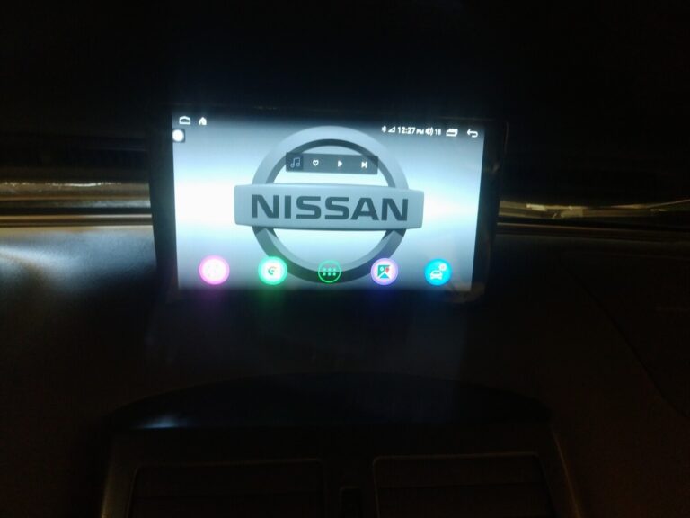
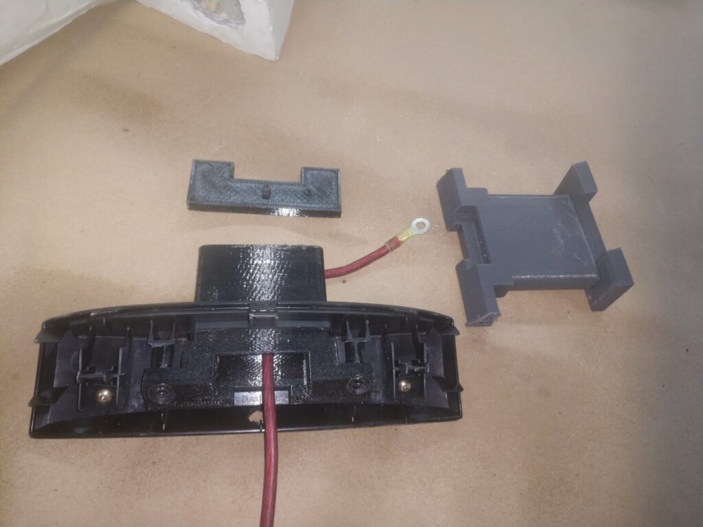
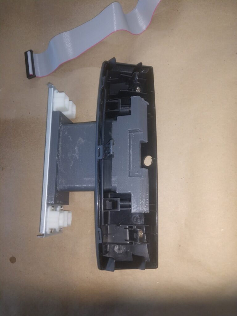
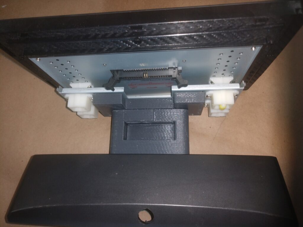
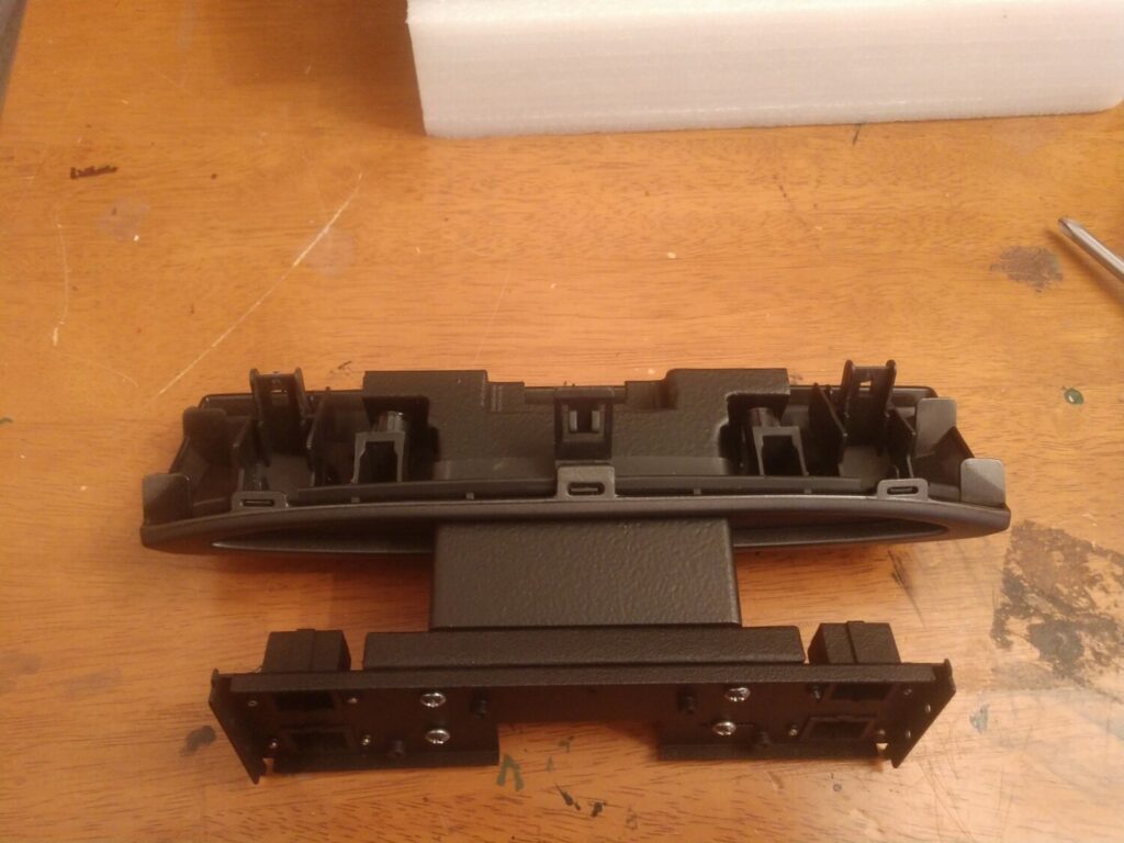
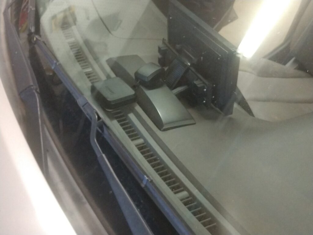
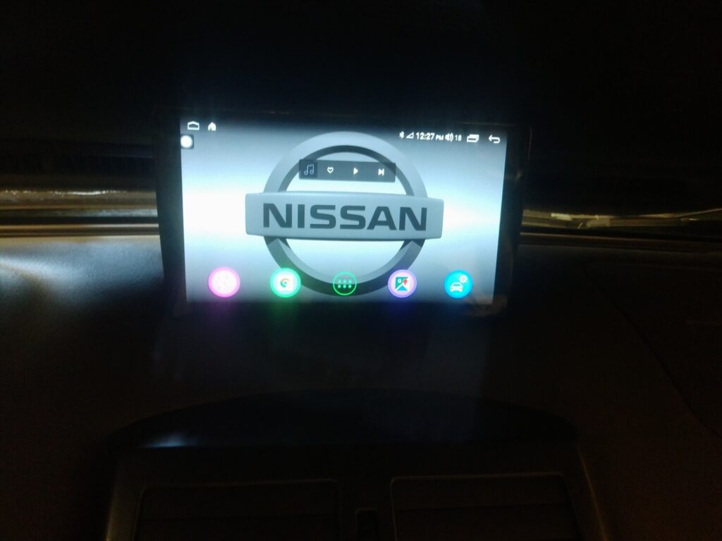
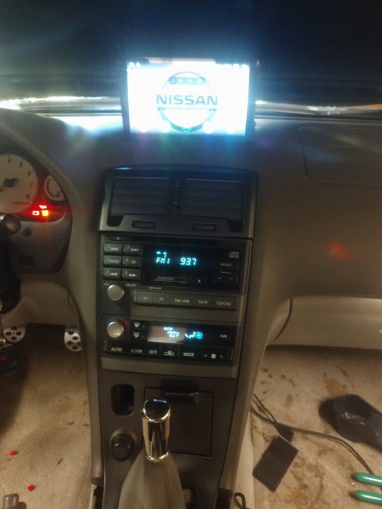
It has a USB input, A2DP BT (via interface), controls my DSP as well. The screen unit’s output can go through the Bose or straight to the DSP via optical cable. My end goal is to get Windows programs running on it. Think Datascan and Minidsp software.
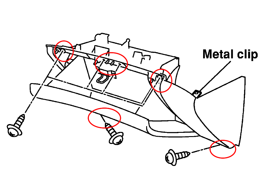
2. Remove the 4 screws holding the the glove box, two at the top and two at the bottom
3. Once the screws are removed pull out the glove box. You may need to use a crew driver to undo the right/top clip.
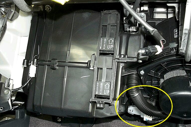
4. With the glove box removed, you will be able to see the “Fan Control Amplifier” for automatic air condition system or “Blower Motor Resistor” for the manual system.
5. Remove the 2 screws holding the Amplifier/Resistor, pull out the Amplifier/Resistor and install the new one.
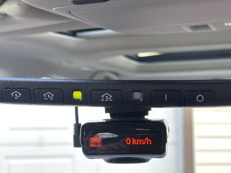
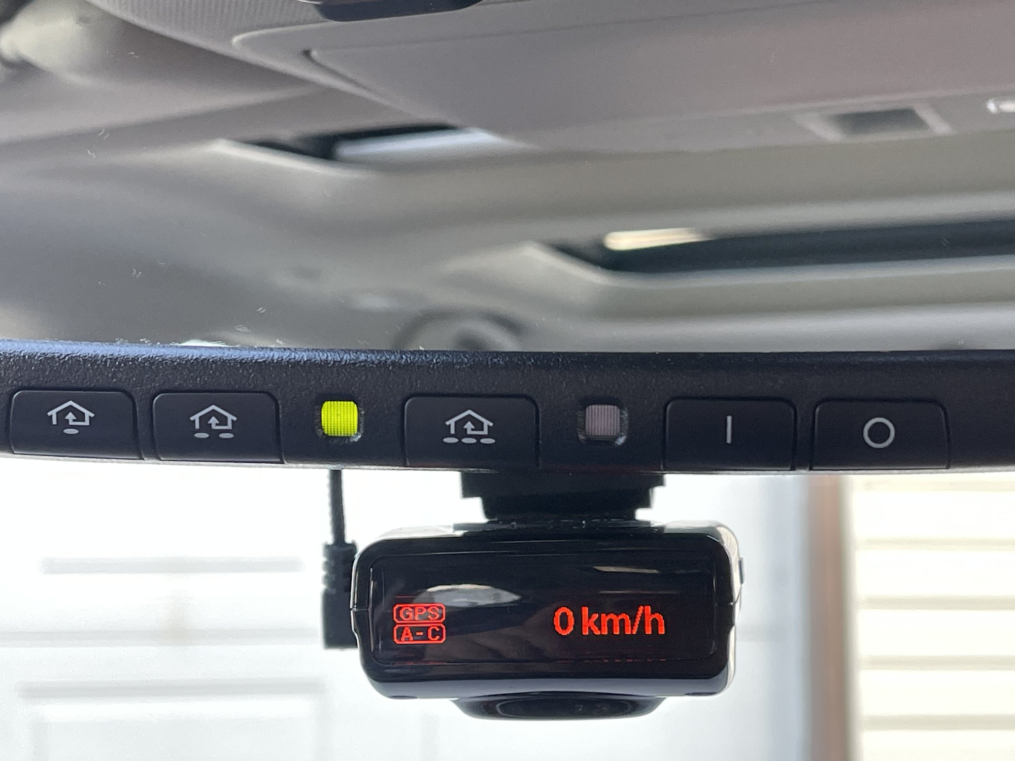
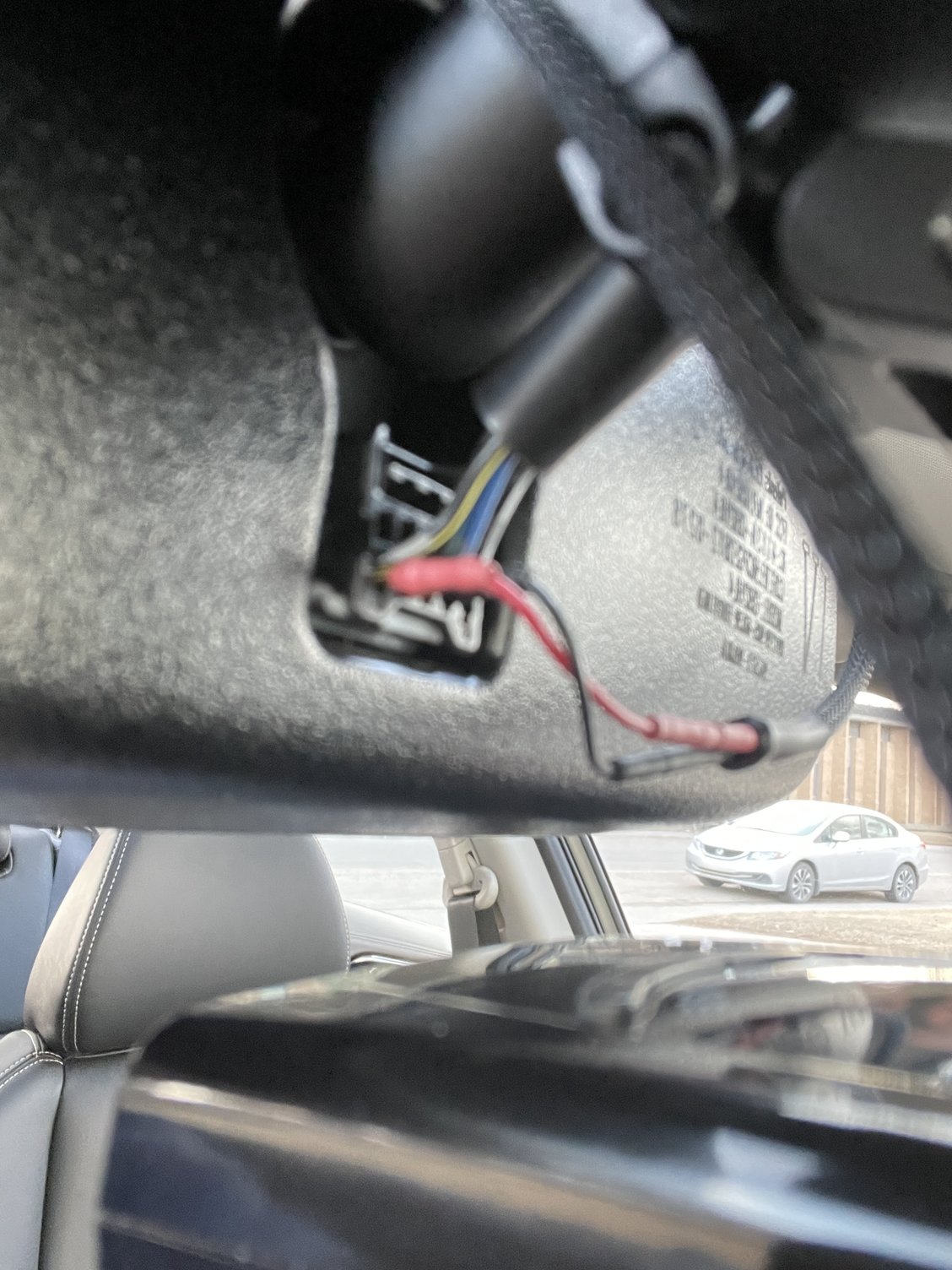
Just finished hardwiring Radenso pro-M with Blendmount and Mirrortap to my 2020 Maxima Platinum over the weekend. This is for rearview mirror with Auto Dimming and Homelink.
White/Black wire is + constant 12V (near driver side)and the “third” wire Black is – Ground.
Yellow/Black wire is + for ACC 12V. (passenger side)
Pricing is for March 2021
Mirrortap MTX-2015 US $59.52 (blendmount.com)
Radar detector used is Radenso Pro-M CAD$680.38(Bestbuy.ca)
Mount is BlendMount BRD-200R CAD$159.56 (Amazon.com)
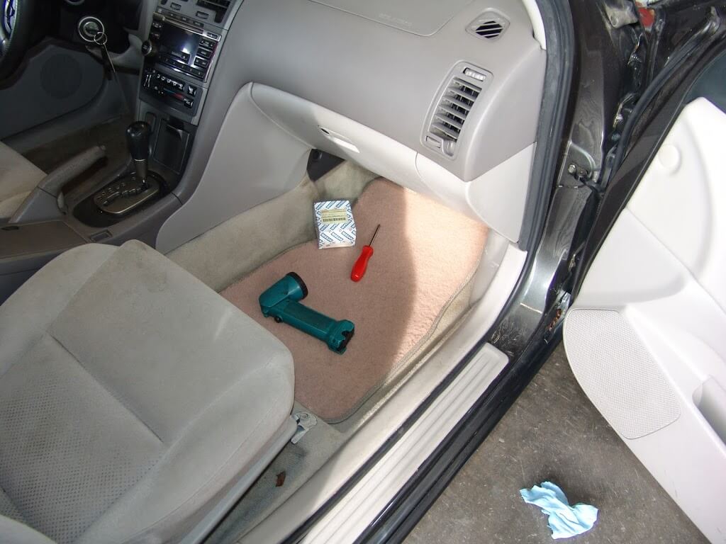
This 2003 Nissan Maxima came in with the complaint that only the highest blower speed was working. The air would not blow at all, on the lower speeds. Suspecting a faulty blower resistor, I went to the passenger side of the dash.
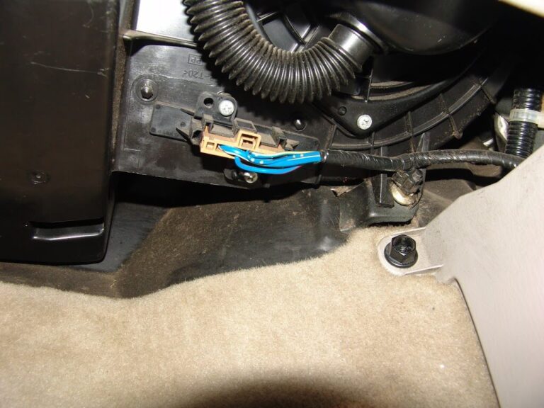
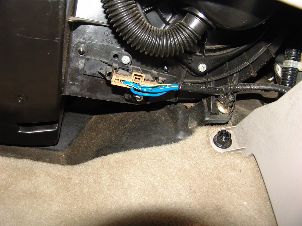
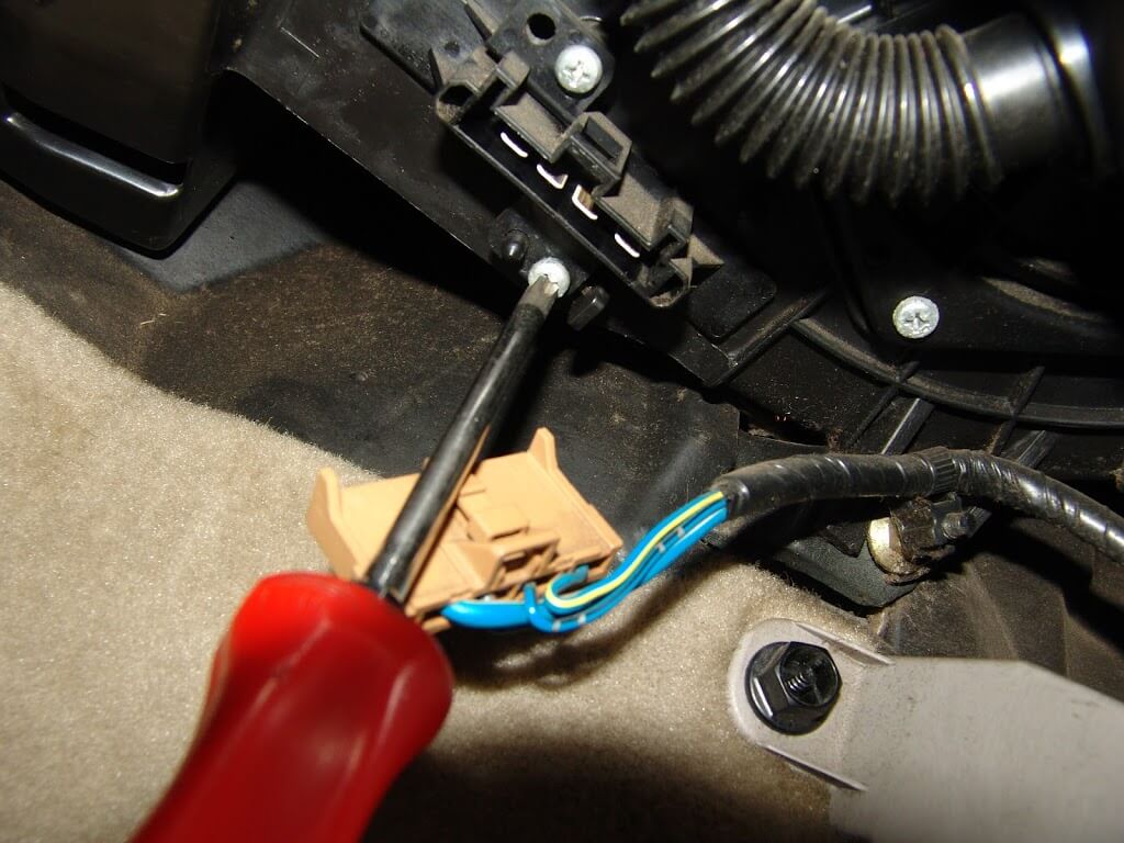
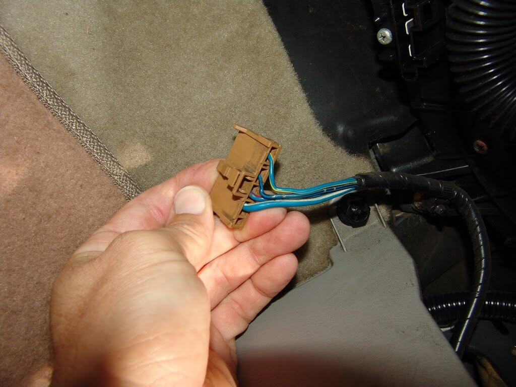
The blower resistor is located near the firewall under the passenger side of the dash. It is the piece that the connector with blue wires is attached to.
Two phillip’s headed screws hold the resistor to the blower housing.
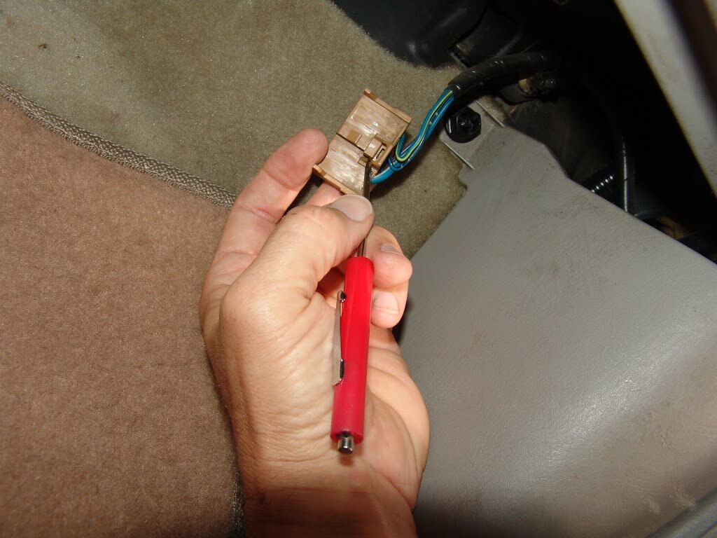
To release the locking tab, it needs to be pushed in where I am pointing at with my pocket screwdriver.
If you want to test the system this is what you will need to know.
The blower resistor and blower switch are on the ground side of the blower motor circuit.
With the resistor harness disconnected and the ignition on, there will be bleed through battery voltage on the larger blue/white wire. In the blower switch position 4 or high the blower switch directly connects this wire to chassis ground and the highest blower speed is achieved.
When the blower speed is set to the 3 position the ground is sent from the blower switch to the resistor on the blue/red wire. It passes through one resistor and the speed is reduced slightly.
When blower speed 2 is selected the ground again is sent form the blower switch to the resistor but this time it is sent on the blue/yellow wire. At the resistor is passes through two resistors and the speed is dropped even further.
When blower speed 1 is selected the ground signal again is sent from the blower switch to the blower resistor and this time it is on the blue/black wire. At the resistor is passes through three resistors and the lowest blower speed is achieved.
If there is no bleed through voltage at the blue/white wire you will need to see if there is power on the white/blue wire at the blower motor itself.
If voltage is not present on the white/blue wire at the blower motor you will need to check the fuses and relay. If power is present the blower motor is faulty.
I also wound up checking and changing a restricted cabin air filter in this vehicle. It is likely that the dirty filter contributed to the resistor failure.
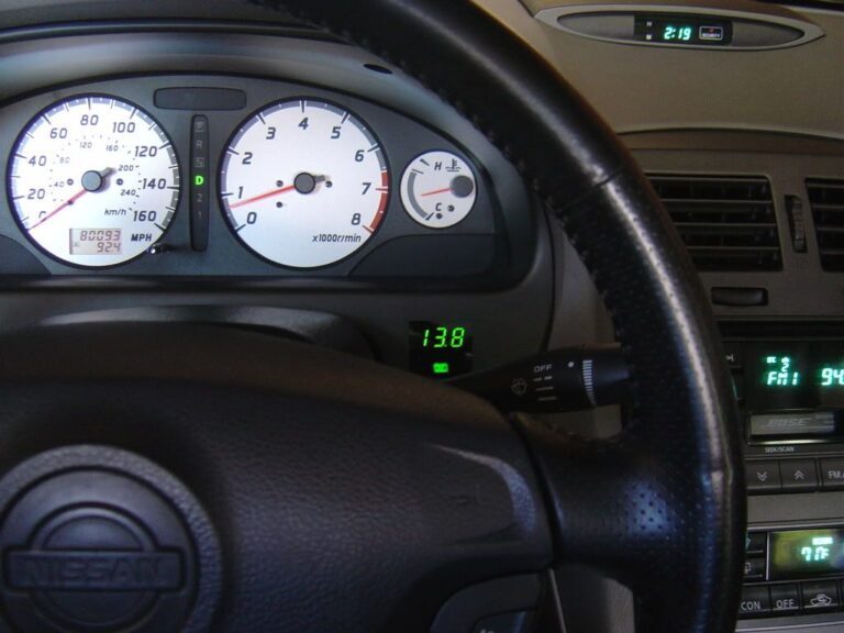
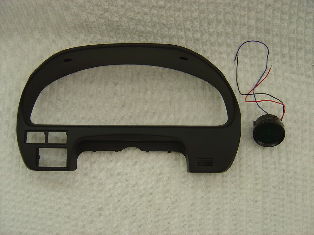
I love voltmeters. They tell you if the alternator died and you are running on the battery. Or in our case, the voltage regulator died and the car’s electrical system was seeing 18.6VDC. Luckily, the ECU survived. All cars should have a voltmeter, and since El Maximo didn’t, DIY to the rescue.
Car is 2001 SE AE with AT. Gauge is Cyberdyne A000E160N green LED digital voltmeter with adjustable hi/ lo warning, about $40 online. I saw no need to adjust the hi/ lo flashing display set points. This particular gauge would dim when the running lights were turned on, but would not go back to the full bright display if the running lights were turned back off. So, I simply ran the gauge on full bright and used a small piece of window tint I picked up off the floor at the local window tint shop. Drove over there, saw a small piece on the ground, asked if I could have it, and it was mine.
It all starts here:
Back of the gauge. Black is ground, red is positive, purple is for dimming (didn’t use):
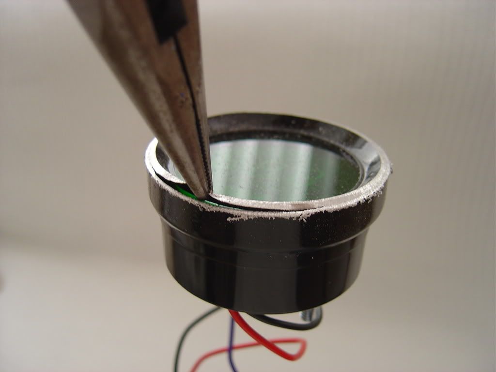
Cutting the gauge case open:
Pull:
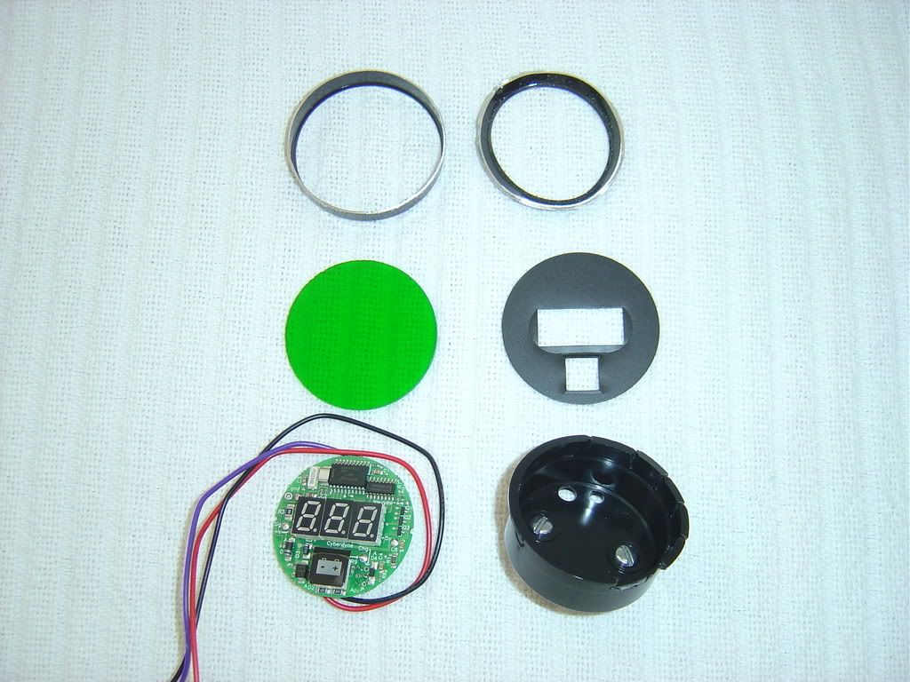
Disassembled; only the circuit board and the green lens get used:
Thin!
Mask it:
Paint it:
Now the fun part. The green plastic lens was warmed on a teflon pan in the oven, then quickly removed and allowed to cool off on the instrument cluster cover to form to the cover’s shape. Mild pressure was used to keep the lens on the cover. A square hole was measured and transferred to the instrument cluster cover. Using a drill, exacto knives, files of various sizes and tooth shape, and sand paper, a perfectly square opening was made in the instrument cluster cover. Then the lens was cut to fit, taking a tiny bit off at a time to insure a perfect friction fit. Super glue was used to permanently attach the lens to the cover. Capillary action draws the glue into the tight joint. The water-thin super glue dries, shrinks, then more super glue is applied. Did this three times. Rock solid and it is perfectly flush, better than what is seen in this picture:
Hot glue gun is your friend:
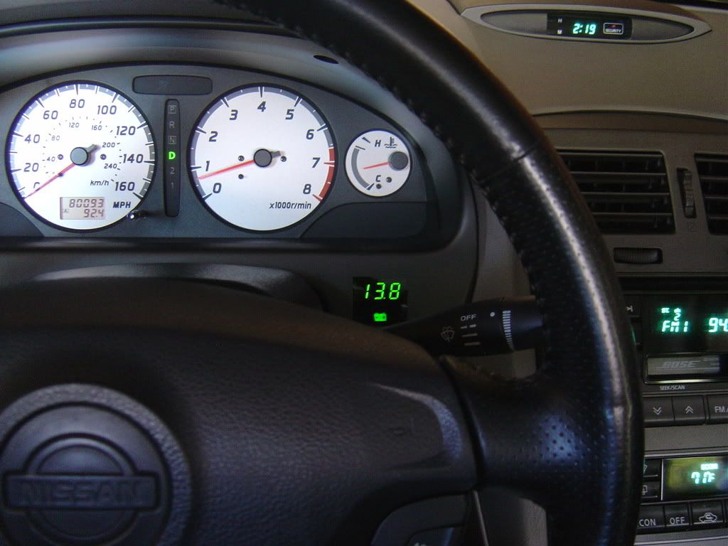
Concluded: Finished!
If I did it again, I would use dark tinted 3/16″ thick acrylic plastic. Other than that, I am very happy with the results!
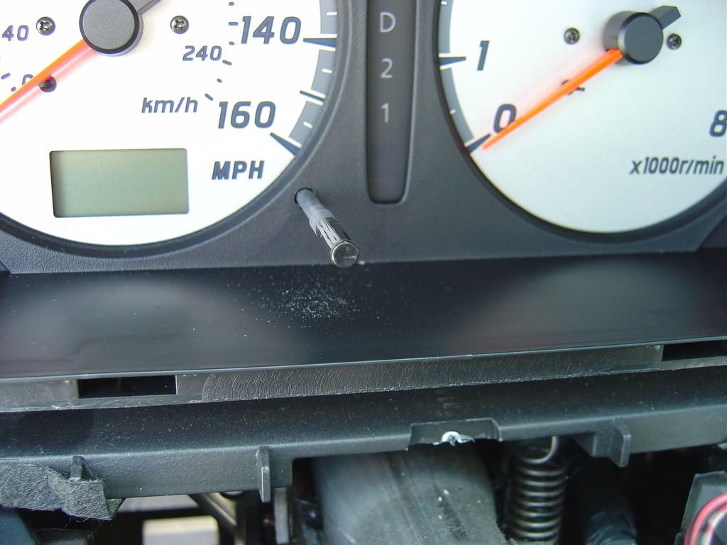
While I was in there, I removed the clear plastic cover from the instrument cluster and removed the dust that made it’s way inside through the hole that the trip meter reset button passes through. You know, this dust:
Hi, everyone. First time site post, long time reader. I still love my ’02 Maxima SE, 6-speed manual! Thanks to everyone for all your stories, advice, and wisdom.
I read the above suggestions, but chose an alternate sound/chime/buzzer/speaker solution. My option took me less than an hour; (I cut some corners.) I wanted to share my approach for those who don’t like cutting wires, disabling the door button, and want to easily reverse the “fix” in the future. I hated when I wanted to play music with my driver door open and the keys in the ignition for the radio — that annoying chime would beep non-stop, interfering with my music. But I didn’t want to lose the car’s ability to know when the door opened/closed (for lock and alarm purposes.) I still like seeing the “door-open” visual indicator; and i don’t like cutting OEM harness wires if I don’t have to.
My method involves removing the piezoelectric plate (thin silver element) from the ECM’s buzzer. It may not be the perfect solution, but it’s much easier than it sounds. Remember taking apart your old digital watch to replace the battery, and noticing the tiny spring that makes contact with the silver element in the battery compartment? It’s kind of like removing that element — the watch no longer made sound if the plate was missing/damaged, and that’s what this fix does. It removes the plate.
The only drawback is that now I won’t hear ANY sounds that the ECM tries to make for me, because the speaker is incomplete. One useful warning sound I will miss, for example, is when I leave my headlights on after I take the keys out of the ignition. (It could happen after driving through a long tunnel or a parking garage during the day, and forgetting to turn them off at the end of the trip.) That loss aside, this is what I did to silence my annoying door-open sound:
1. It’s probably good to disconnect your car battery’s negative terminal at this point. (I didn’t bother, but I’m a risky nut.) Your ECM (engine control module) is important; so use your better judgment.
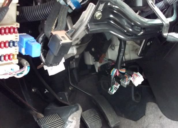
2. Under the steering wheel and behind the lower dash, locate the ECM module mounted on a flat metal post. The ECM is a white rectangular box mounted tightly, that slides off easier when a flathead screwdriver is inserted between the ECM plastic and the metal mount. (A circular nub on the plastic keeps it secure by pressing against the metal mount.) Remove the ECM and then disconnect the 3 harnesses.
Location of the 3 ECM wire harnesses:
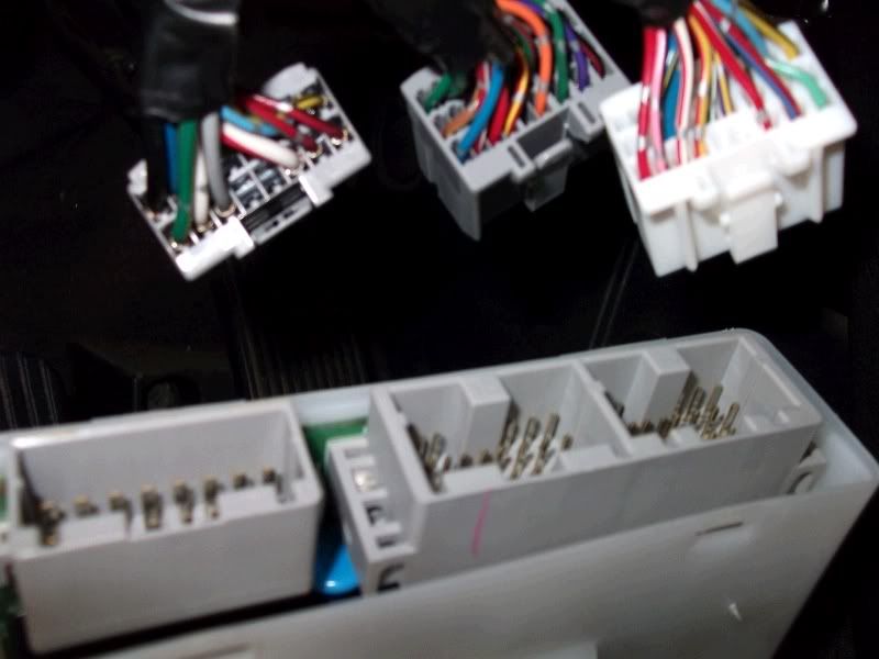
Closer look at harnesses:
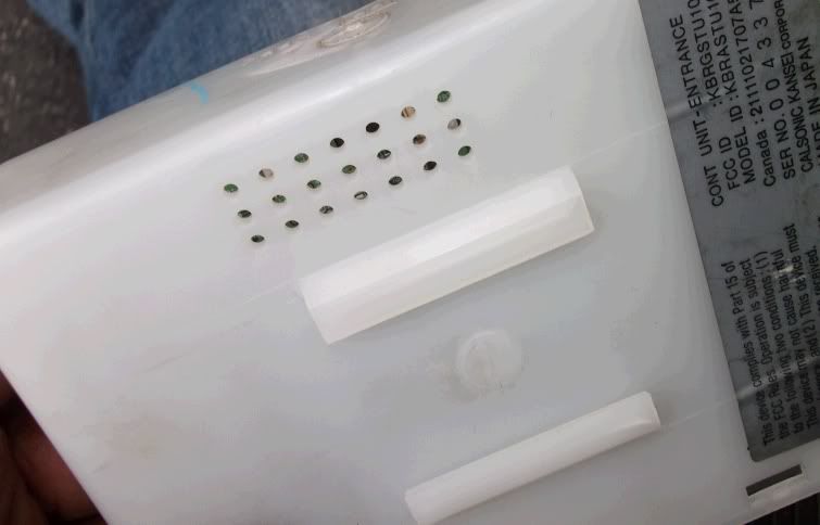
Plastic nub on ECM:
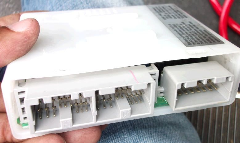
ECM in hand:
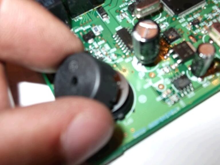
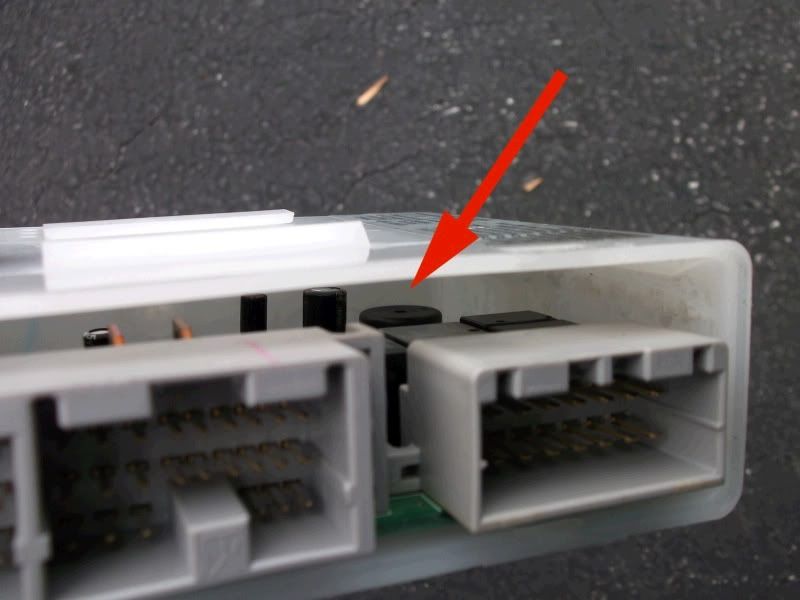
There’s the piezo buzzer we want to get to:
3. Slide the ECM circuit board out of its plastic protective case. Don’t rush, since you don’t want to damage the board or the case. It requires some cautious strength to wiggle the board free from the plastic guides. Easy does it. Used a screwdriver or needle-nose pliers if you need to. It’s probably good to ground yourself free from electrostatic charge before doing this, as not to damage the electronics with a static charge. (Again, I’m a nut and so I didn’t bother.)
4. With board in hand, find a clear table so you can take apart the piezo speaker without losing any pieces. Carefully pry the black cover off the underlying base of the piezo buzzer, to reveal the inside:
5. That shiny, thin, silver disk is the piezoelectic element that you want to remove. Take it off. (It’s unsecured, and will easily fall out once you take the black cap off.) This is the critical component that makes the chimes/sounds/warnings. Save it somewhere, in case you ever want to reverse the procedure down the road.
6. Replace the black cap (or not — it’s optional), and put everything else back together. Don’t start the car without the ECM wire harnesses back in their expected receptacles.
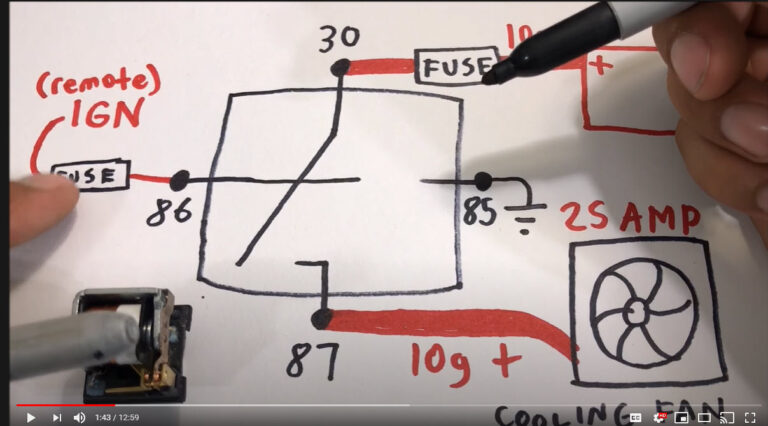
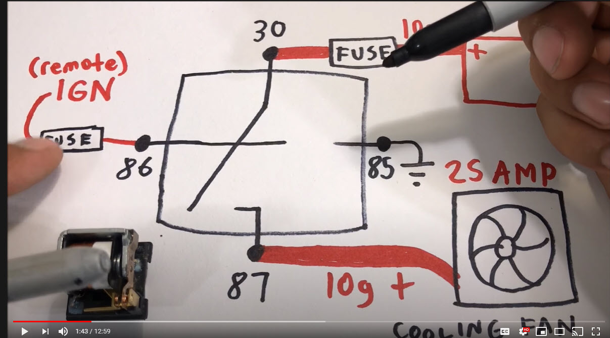
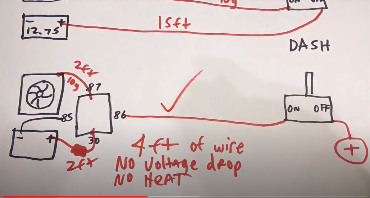
This is an awesome video explanation on Automotive Relays. Many Nissan Maxima members like to install high-performance cooling fans. If not properly installed using a relay, you can risk burning the wiring out. This has happened to us various times. The video below will help you understand how to do it correctly.
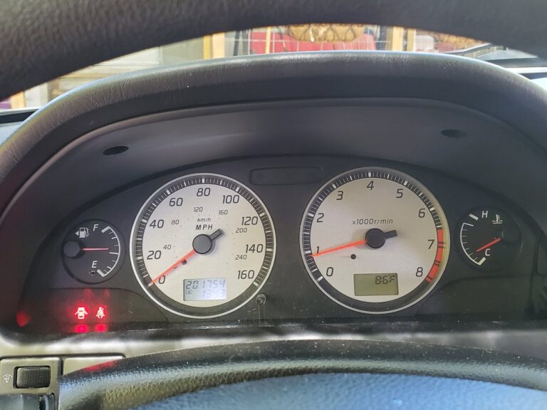
Hope this can help anyone that wants to use an aftermarket fuel gauge. May already be a write up on this but I couldn’t find it. I decided to go with aftermarket after not being able to find a cluster with one that actually works correctly.
Used one from Glowshift. Regardless of what gauge brand you use, results will be similar. After a few trials and error I got the new one working with no cel and gas lights on. I chose to mount the new gauge where the ashtray is. Didn’t take pics of how I wired power to it but I just used wire taps on the constant and switched ignition to the stereo.
Under the back seat I chose to just cut the green signal wire going to the fuel pump sending unit. With this wire not connected you will get a cel for high signal input. It uses a variable ground signal from the sending unit. You will also get the low gas warning light and dte will flash. I used a 47 ohm resistor and grounded the side going to the body harness and hooked the new gauge up to the side going to the pump. Ignore the butt connectors. This wasn’t the finished product. It was soldered after everything was working right.
If you ground the wire without the resistor, you will still get a CEL. After it’s all done with, my OEM gauge sits right above half and I have no CEL. You should be able to use any resistor between about 10 and 75 ohms. I opted for 47 OHM. Since it was in the middle of the resistance values of the sender. Last pic of where it sits with it all finished up. I’m happy with it.



















 Closer look at harnesses:
 Plastic nub on ECM:
 ECM in hand:
 There’s the piezo buzzer we want to get to:
 3. Slide the ECM circuit board out of its plastic protective case. Don’t rush, since you don’t want to damage the board or the case. It requires some cautious strength to wiggle the board free from the plastic guides. Easy does it. Used a screwdriver or needle-nose pliers if you need to. It’s probably good to ground yourself free from electrostatic charge before doing this, as not to damage the electronics with a static charge. (Again, I’m a nut and so I didn’t bother.)
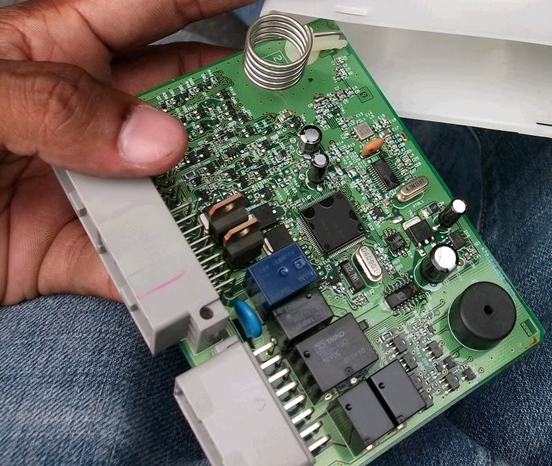 4. With board in hand, find a clear table so you can take apart the piezo speaker without losing any pieces. Carefully pry the black cover off the underlying base of the piezo buzzer, to reveal the inside:
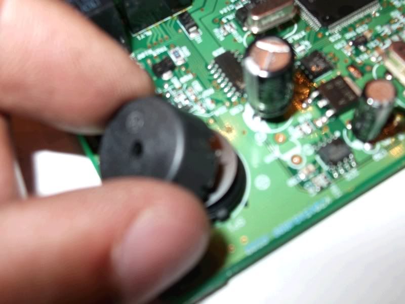 5. That shiny, thin, silver disk is the piezoelectic element that you want to remove. Take it off. (It’s unsecured, and will easily fall out once you take the black cap off.) This is the critical component that makes the chimes/sounds/warnings. Save it somewhere, in case you ever want to reverse the procedure down the road.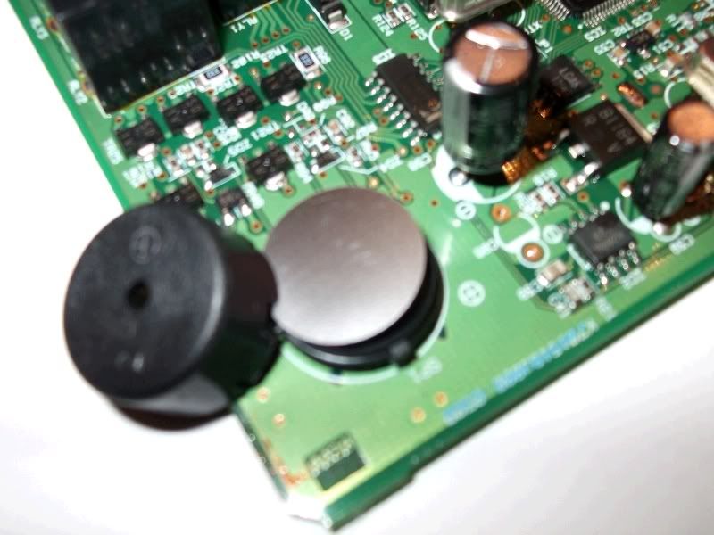
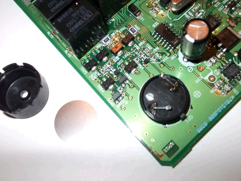 6. Replace the black cap (or not — it’s optional), and put everything else back together. Don’t start the car without the ECM wire harnesses back in their expected receptacles.