

Last Updated: 10/22/2022 @ 07:30 pm
This content was submitted by supporters (social media and/or online forums) to help inform and educate others. If you would like to request removal click here. For additional info, please visit our Legal Terms & Conditions.
Community Member Credit: gtrrider / VQPower
Brief Details: What can the device be used for:
In the VTEC AFC II, the VTEC changeover point of a vehicle with a VTEC engine (in our case 00VI/MEVI) can be adjusted at an optional engine RPM. This fuel adjustment controller can increase and decrease fuel in a wide range of +50% to -50% by 1-point increments for the specified engine rpm. RPM points can be set in 100 rpm increments and make fuel correction according to the throttle position.
The second-generation SAFC is a fuel computer that adjusts fuel/air ratio by modifying the air-flow meter/MAP sensor signal. The SAFC features a user-definable, eight-point, adjustable fuel curve that can be set in 500 RPM increments. The range of fuel adjustment is +/- 50% at each of the user-defined setting points. On hot-wire vehicles, the Deceleration Air Flow Correction function is capable of curing the erratic idle and stall problems associated with open-atmosphere blow-off valves on hot-wire air-flow meter systems. The SAFC is capable of monitoring and replaying the following data channels in Numerical, Analog Meter and Graph displays: Intake Manifold Vacuum/Boost Pressure, Air Flow Capacity, Intake Manifold Pressure, Karmann Frequency, Engine RPM, Throttle Position, and Air Flow Correction %.
Tools Required: Necessary components used to install the VAFC to an A32:
- Wire cutter
- Wire Crimper
- 10(or 12mm) socket and ratchet
- Soldering iron with 16-22ag solder
- Electrical tape
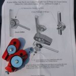
- Snap connectors
Warning: I am not responsible if you fry your electrical system or damage your engine. Use caution when working with electricity and please disconnect the battery before proceeding!
Installation: Installing into your 1995-99 Maxima
You will need to access the passenger side of the ECU so from the passenger side of the car remove the kick plate to reveal the sealed harness to the ECU. Undo the 10mm socket from the center of the harness plug and separate the harness from the ECU. Pull off the clear plastic shielding which encases the wiring and we will begin the taping of wires for your new S/V-AFC II.


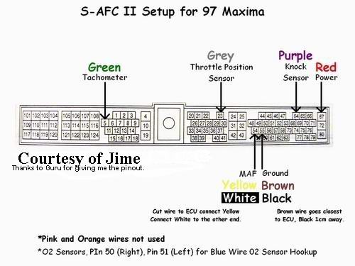
From here you will need to match up accordingly the wiring from the V-AFC II Harness to the wire location (NOT COLORS) on the ECU harness. Please note that you will not be using the Light Blue, Purple, or Orange wires from the V-AFC harness, tuck them away. Take note of subscript on ECU harness image for the location of Blue(O2 sensor hookup wire). Solder all wires securely and cover with electrical tape. Below are an V-AFC wiring diagram, an S-AFCII wiring diagram, and also the pin-outs on an A32 ECU harness, please use them properly to match up the wires. Failure to do so will result in damaged electronics or engine.


Initial V-AFC II Setup: Before you can start the engine you will need to setup the V-AFC.
Now that you have securely solder all the necessary wires to the ECU you may now begin the setup to make sure you do not damage the engine on startup. Turn ignition to the ON position but DO NOT start the engine and your newly installed V-AFC will come alive. Navigate through the menu’s, be sure to take it slow as not to incorrectly configure a vital setting. Move to the ETC menu; hit right on your joystick, scroll down and continue into Initialize, and toggle over to Yes. Accept the choice, after doing so wait 5 seconds and turn the ignition to the OFF position. Doing so will clear any unwanted information stored in the device if you happened to purchase the device used.


Return the ignition back to the ON position but DO NOT start the engine. Your V-AFC will activate again for more information to be stored. Navigate into the ETC menu again, and proceed to enter the following:
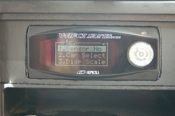


Sensor NO: 4 IN, 4 OUT (Assuming you are running a A32 MAF) –Otherwise*1*
Car Select: 6 Cyl, Arrow UP and RIGHT, V/T 1
Sensor CHK: Ensure sensors are giving readings
Further tuning settings will need to be fine tuned while on a dynamometer. Once all settings have been checked over, turn the ignition to OFF wait 5 seconds and return the ignition to ON one last time. While your V-AFC is booting let the throttle rest at 0% for 10 seconds, and depress the throttle to 100% for 10 seconds and release. You have now completed the learning sequence for throttle positions and you can proceed to start the car.
![]()

Comments are closed.