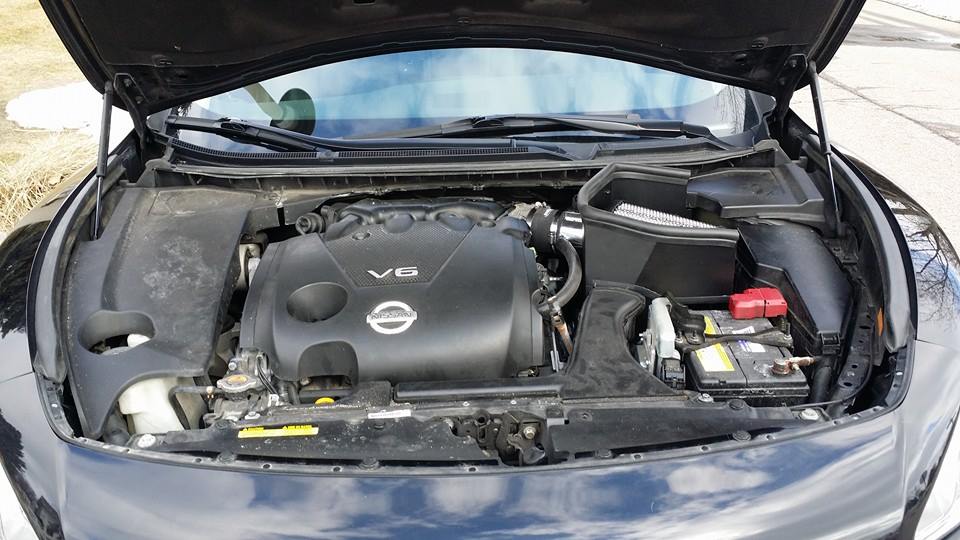
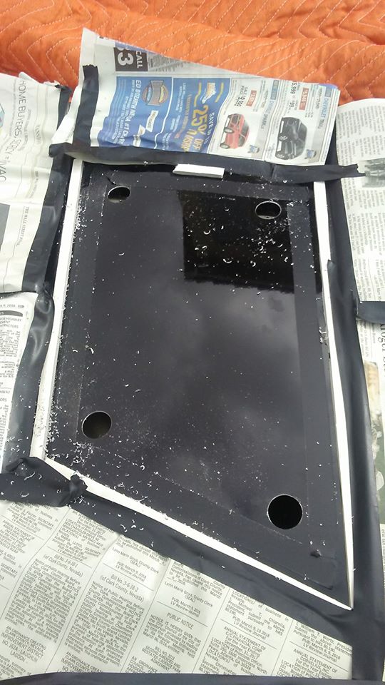
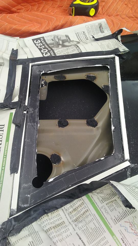
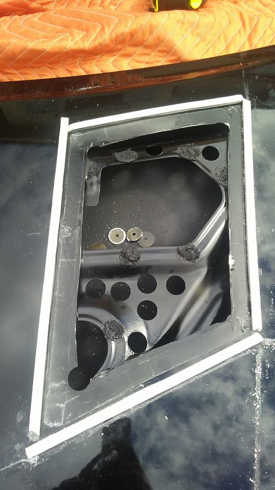
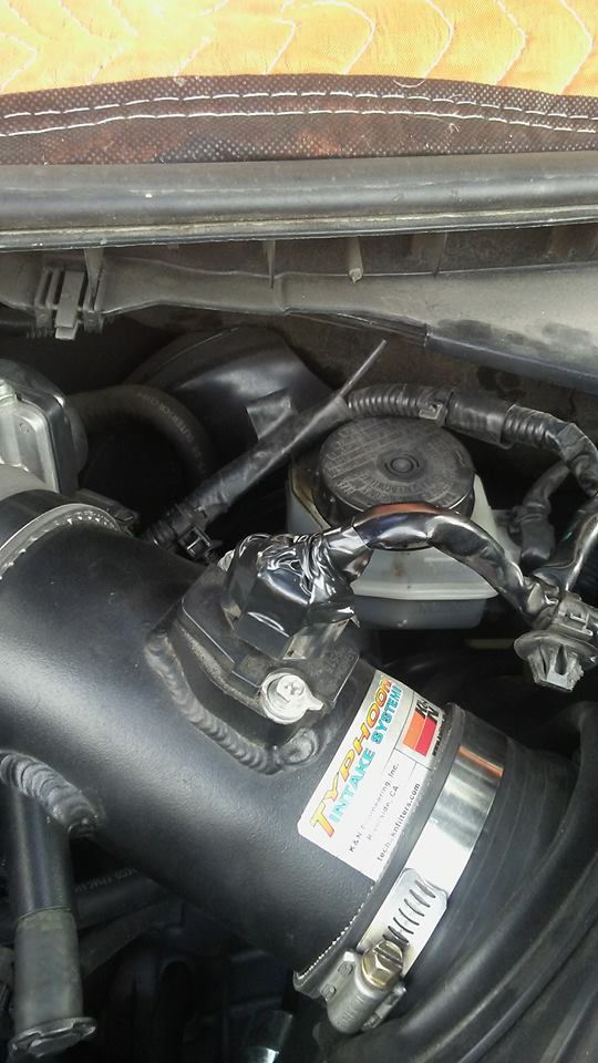
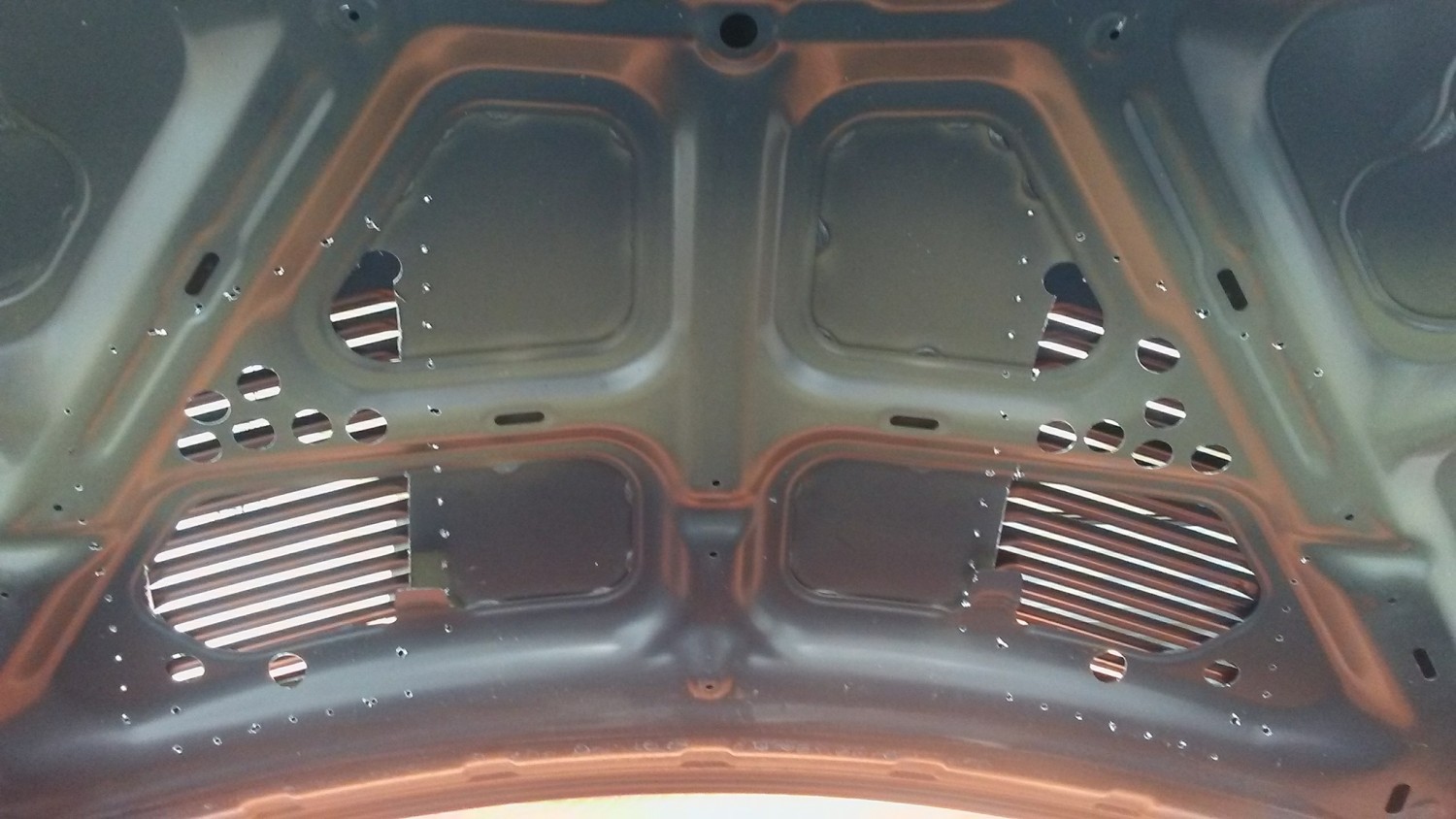
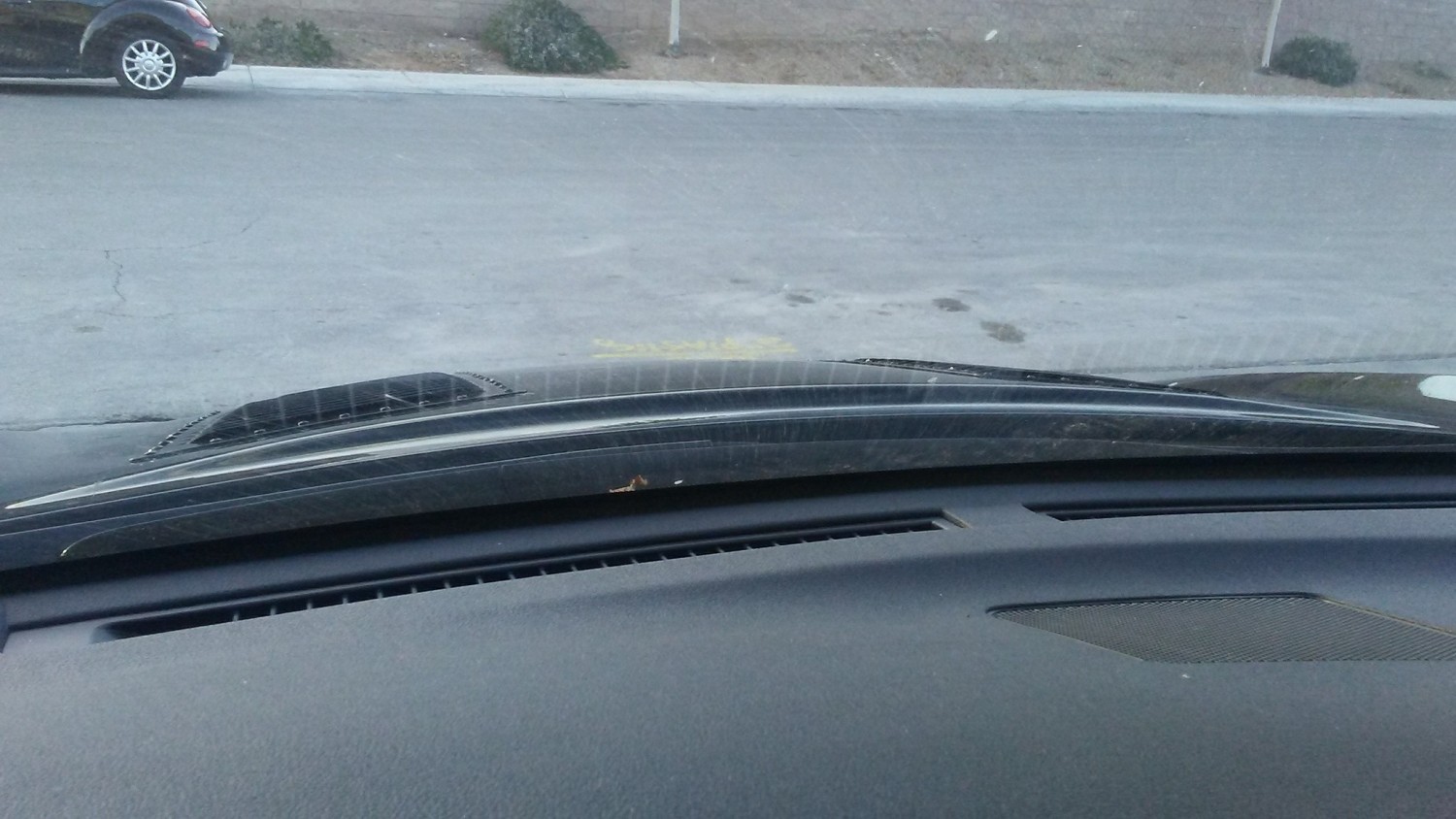
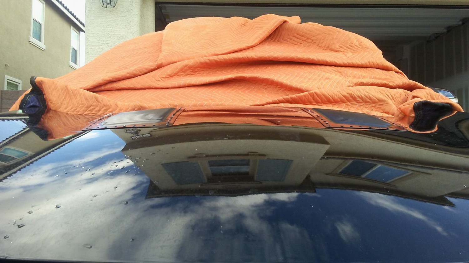
I know ill get roasted by some and that’s ok. If you really research the tools you have and how to use them then any job isn’t bad. This took me a few hours but I’m happy with the results. Morning drive this morning and intake and plenum didn’t even get warm. That’s what I’m talking about.
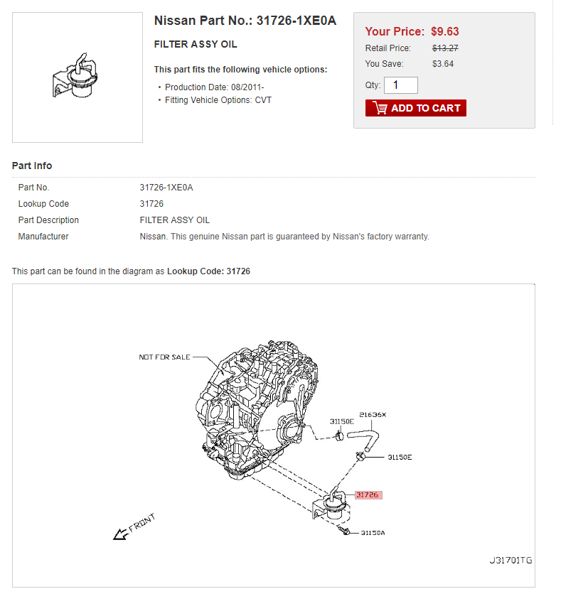
If you’re up for a CVT transmission fluid drain/refill, it is also a good idea to change the CVT transmission oil filter. Often times, if you go to the dealer and ask them to change the CVT oil filter….they will look at you like you’re crazy. Stay calm, the oil filter does EXIST! It is very easy to change and swap while you do your drain/refill.
Most dealerships are not aware of this filter replacement because Nissan does not call for this maintenance change in any of their maintenance intervals. So to their credit, it’s not their fault that they are unaware. However, for $10 bucks this is something you can do yourself or dealer as part of your transmission fluid drain/refill.
Part Number: 31726-1XE0A Part Name: FILTER ASSY OIL Price: $9.00-10.00
It is located behind the splash shield in the driver’s side wheel well. It’s held by a 10 MM bolt and two hose clamps. Simple enough!
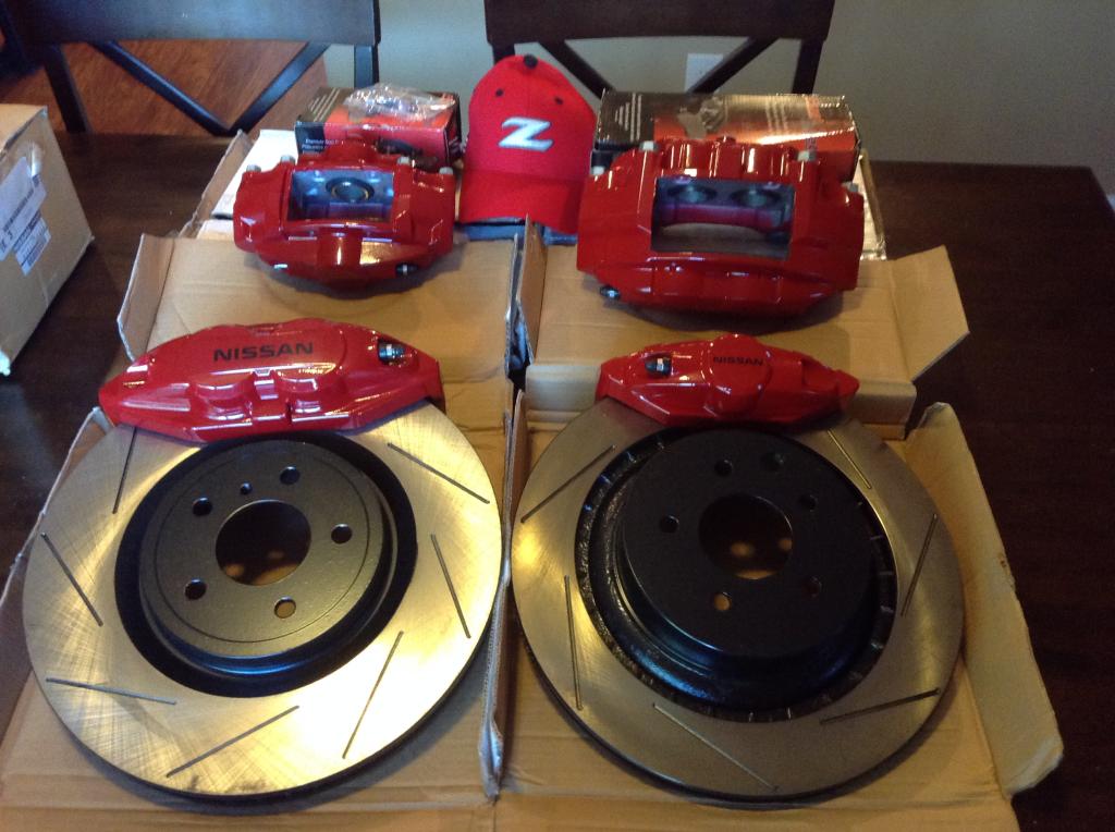
It was just under $1,800 shipped for the kit. Shipping was included at $125.
The options were:
Slotted Rrotors
Banjo Bolts
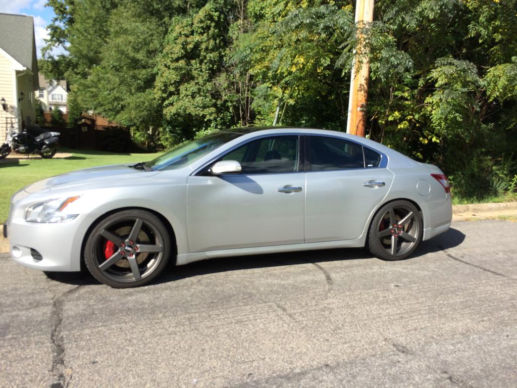
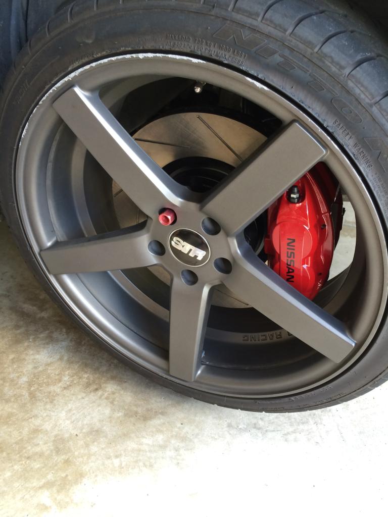
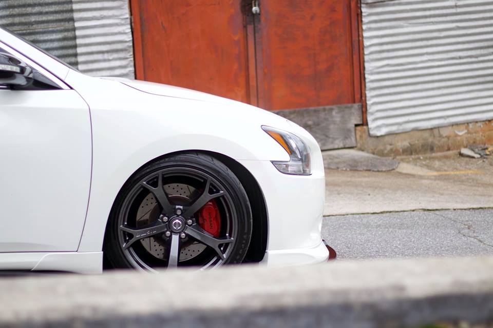
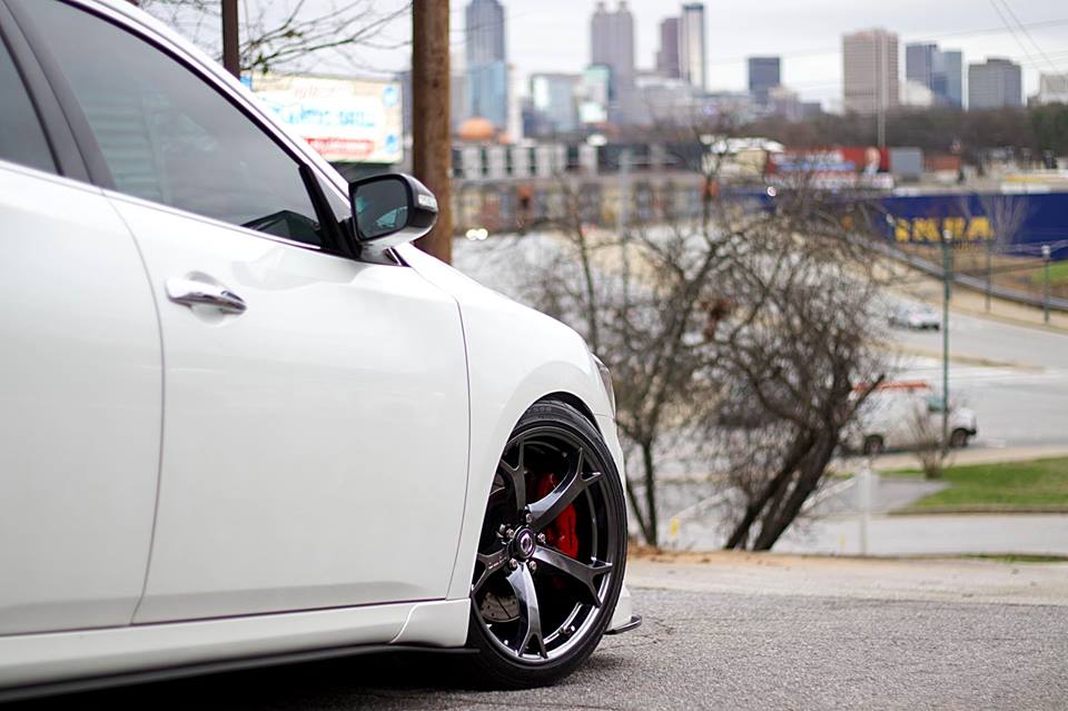
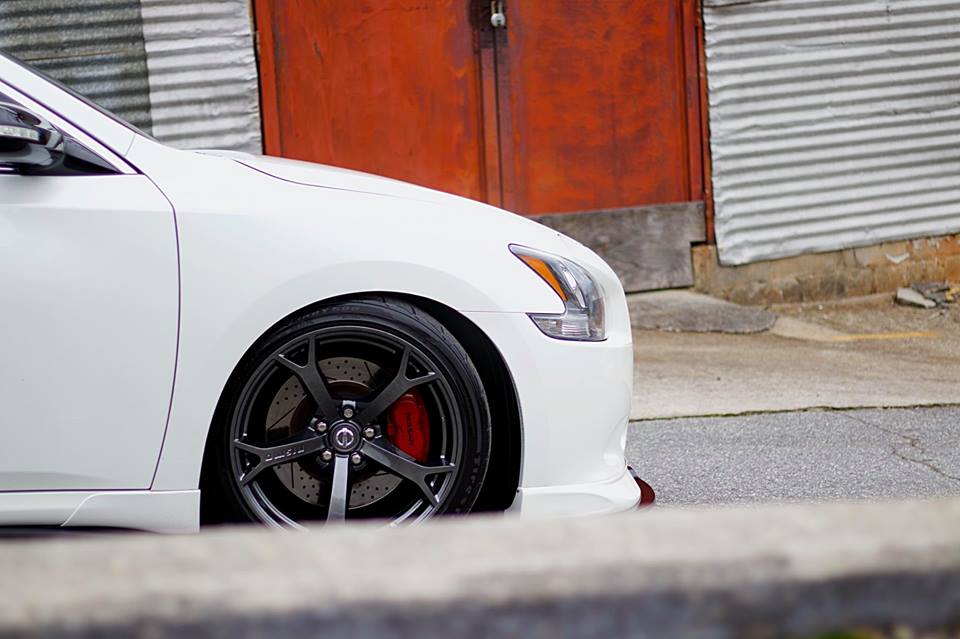
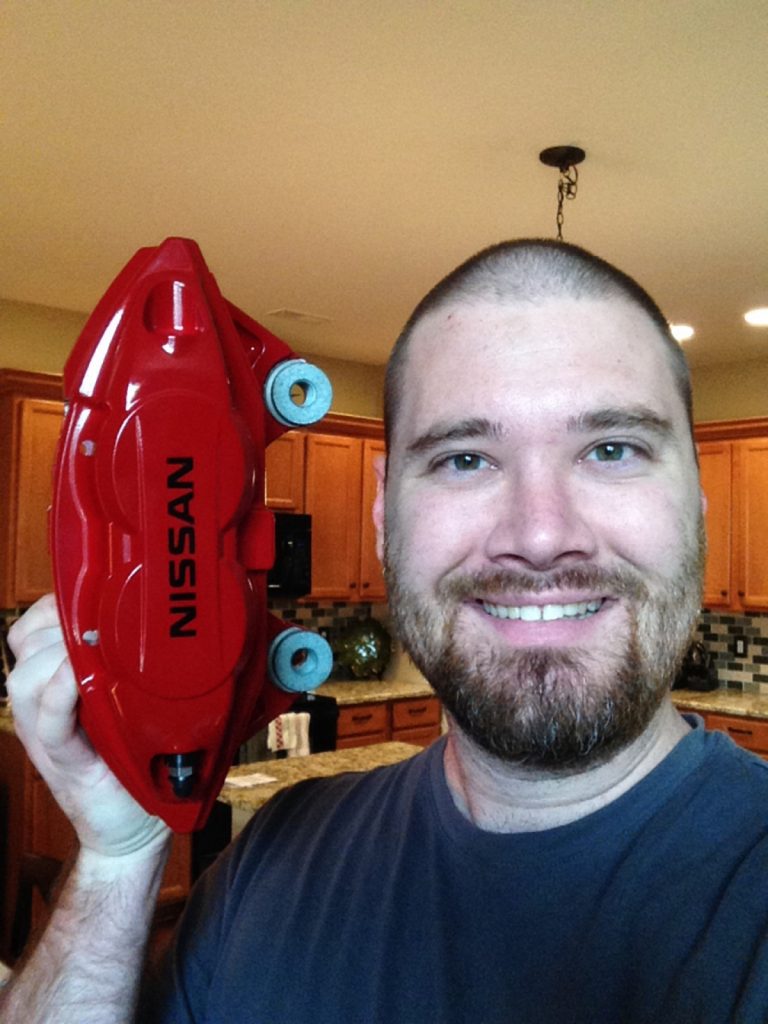
Red Calipers
Standard Ceramic Brake Pads
If you attempt this yourself, you assume that you have some mechanical aptitude, and already know how to bleed your brakes when you are done. Make sure you do not run out your brake fluid reservoir. Keep it topped off. Multiple fills per caliper.
Tools needed:
Jack and jack stands
Fluid Catch Tub
Small funnel, mine came from the camping section at walmart
1/4″ hose, clear, 2 feet in length. Not an absolute, but will help when you bleed brakes.
10, 12, 14, 19 wrenches, and a 21mm if you have it
12, 14, 19, 21mm sockets.
Flat head screw driver
Impact driver: Not an absolute, but will make your life easier
Rubber mallet
Angle grinder with cut-off wheel.
Paper towels
Gloves, if you like your knuckles.
1L bottle of brake fluid.
Safety glasses, or motorcycle helmet if you prefer.
I chose to complete one corner at a time, and bleed after each corner installed.
Step 1. Jack the front of the car up, place jack stands, and remove front wheels. Step 2. Remove the front caliper bolts. Use the 14mm.
Step 3. Remove the front pads.
Step 4. Tuck the caliper out of the way, don’t leave it hanging.
Step 5. remove the carrier with the 21mm. I was not able to make mine move with the wrench and some effort, so I just used the impact gun. Mine were very, very tight after 115kmiles of not being touched.
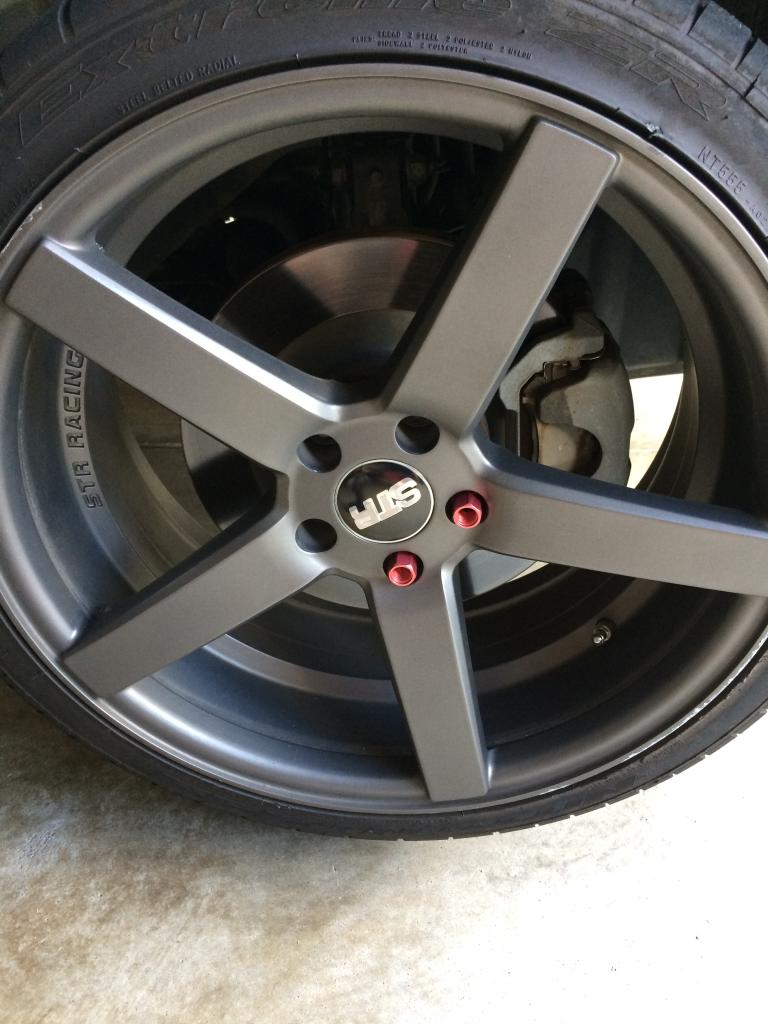
Step 6. I opted to test fit everything and make sure I wouldn’t have problems before I went any farther. Spoke design can influence fit. That is the picture I posted previously with the single lug nut
Step 7. Place the new rotor on the hub, and use one or two lug nuts to hold it in place. Depending on your lug nuts, you may need some washers. You don’t have to do this but it makes life easier.
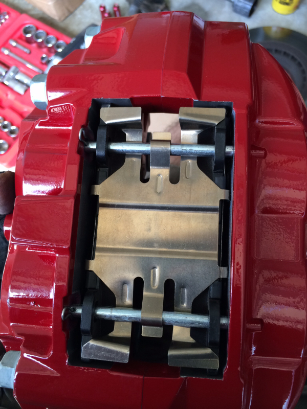
Step 8. Now you need to add brake pads to your new caliper. Squeal tab goes on the inside. Then you add the spring plate, followed by slide pins. Use the cotter pins to hold it together. The flat head screw driver will help you here.
Step 9. Now you want to bolt this to the knuckle. The new brakes are the caliper and carrier. YOU MAY RUN INTO AN ISSUE AT THIS POINT.
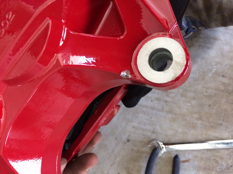
ONE OF MY CALIPERS NEEDED A SLIGHT TOUCH WITH A GRINDER. One of the gussets was slightly oversized during molding, and was hitting the knuckle. I had to remove about 1mm of material in a small section where it was hitting. It would not bolt flat otherwise. One of my calipers self corrected when I bolted it down, and was not a problem, the other needed my help. Make sure it is correct. You could also remove the material from the knuckle if you dont want to scratch your paint.
Step 10. Now we get to make more of a mess. Use the 10mm wrench to remove the bleeder screw from the outside, and open the screw on the inside.
Use the small funnel to fill the caliper. Place the catch tub under the brakes. It does not take much, so go slowly. Once full, replace and close the bleeders. Use the paper towels to wipe up spills.
Step 11. Now we need to swap the brake line. Get the new, shorter banjo bolt ready. Use the 12mm to remove the brake line. You will need the 14mm for the new one. Quickly remove old bolt, slide on new bolt, then screw it into the back of the new caliper. Remember, the order is: bolt, crush washer, brake line, crush washer, caliper.
Step 12. Bleed the brakes for that corner. It will take a bit of time and a few repetitions to get fluid in and air out. Watch the fluid level in your reservoir so you don’t run it out. Use the plastic tube now. Slide it over the bleeder, then you can guide the fluid to the catch pan, and also see if it is air or fluid being pushed out. I recommend outside, inside, then verify outside when bleeding.
Step 13. Complete the same steps on the other side to complete the front swap.
It is fairly simple, and took about 1 hour to complete. If you are inexperienced, plan for 3 hours.
Step 14. Put your front wheels back on, lower the front, raise the rear of the car, and remove the rear wheels.
Step 15. Now we will take care of the rear brakes. Remove the rear caliper and pads. Use the 14mm for the caliper bolts. Use the 19mm for the carrier bolts. The bottom bolts both require a wrench, not socket, because of the tight space. Again, tuck the caliper somewhere out of the way.
You may need the hammer or mallet to get the disks off. Tape around the hat, and on the face of the rotor.
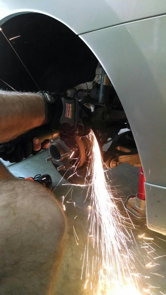
Step 16. This is more involved than the fronts because of the dust shield. You will need your cutoff wheel now.
If you optioned for factory dust shields, you will need to do substantially more work, and I won’t describe the process of removing the parking brake shoes and hub to R&R the shield. You need to remove the protruding ring of the dust shield as well as make room for the new caliper.
It makes a lot of sparks. Wear safety glasses. I do not recommend wearing safety glasses and a hat, as it can direct sparks behind the glasses if they are not well fitting. If wearing a hat, turn it around. My friend was with me, and wore his motorcycle helmet while cutting the other side.
When I showered afterward, there was a substantial amount of metal in my limited amount of hair.
Comparison:
Step 17. Install the pads into the caliper. Again, squeal tab towards the inside. Then place the new rotor on, and bolt on the caliper.
Step 18. Follow the same procedure as the fronts to fill the calipers with fluid, swap the brake line, and bleed.
Step 19. Put the wheels back on, torque everything down, and test the brakes.
Make sure you don’t have any weird noises, vibrations, etc. Bedding, or seating the brakes will vary based on which pads you choose.
Impressions:
WOW, Wow, wow. The brakes bite earlier than before, with a more solid pedal feel. When you really give the brake pedal some pressure, it will quickly lock your seat belt and try to give passengers whip-lash. There is a slight decrease in acceleration. THESE BRAKES ARE 37 POUNDS HEAVIER THAN THE STOCK OPTION. That is ~12lbs each per front, and ~6lbs each in the rear more weight.
If you can afford it, or if you have had them long enough to need replacement, I HIGHLY recommend the light two-piece rotors. You will only add 2lbs to the front and 1lb to the rear with this $900 option.
On slotted rotors:
The direction does not matter for these disks. They are manufactured with straight veins on the inside, or omnidirectional. It is up to you if you want the veins to go forward or backward.
I have heard repeatedly that spinning opposite of wheel travel can cause more noise, so I opted for spinning with direction of travel.
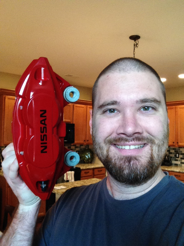
When they are on the car, you really loose the sense of scale. This is what I show people to give them an idea of size:
I purchased this slightly used from the classifieds here for a price that made it worth trying out.
There have been nearly a dozen threads over the last couple of months describing how intakes on our cars just bring hot air into the engine.
The R2C utilized the factory snorkel as well as a heat shield that is gasketed to keep out excessive engine heat.
I am running the black hex filter line, which appears to be an upgrade from R2C. They claim 10hp increase, which I don’t really believe. Their website shows dyno graphs of the increase as well as intake temperature staying identical from stock and after install. Their website dyno charts show the increase starting about 3800rpm, but a decrease till about 3000rpm.
Currently I have a Racingline y-pipe and Stillen light weight under drive pulley for engine modification. Over the next week I will determine if this is just noise or if there is an increase in performance.
We know that if I start getting better mileage, there is a good chance I have lost hp.
Install was very straight forward and took about 30 minutes. Now, I used to work on cars for a living, so if you don’t know what you are doing, or what tools you need (the directions didn’t have the right tools listed) then it will take you 60-90 minutes to complete.
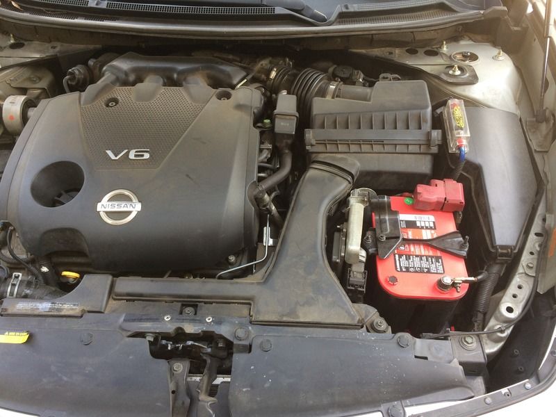
Before:
After:
Initial impressions from install:
The heat shield could be a little more robust. It covers the entire hot side, but I would have finished the box and enclosed the filter a little more. The filter is solid, and I have no doubt it will last the life of the vehicle. Assembly can be a little confusing from the directions.
Initial driving impressions:
Noise. It is definitely louder than the stock box. Resonators on the breather hose and air box are eliminated, as well as the ‘sound tube’ if you still have that on your car. The open design really let’s the motor sing in the cabin. It made me feel like my exhaust sounded better as well, but I’m sure that was just the added engine roar.
There is some low end torque lost. I can still chirp the tires, but nothing like before. To me, it feels more like a ramp up of power being applied. I did not (un scientifically) notice a change in my 0-60 times. If I did gain power, it is above 3500 rpm. That felt better, but it may be placebo from the extra sound. Boy, it sure does sound faster.
And now for some hard core knowledge from someone much smarter than me: This is a copy/paste with a little editing, so some context may be lost.
There are three aspects here:
1) intake air temperature, which we will assume is similar although I haven’t seen any data
2) Restriction across the air induction system–which we will assume is lower if it is performing as advertised
3) dynamic tuning effects–the likely factor here
So your Maxima has the high output version of the transverse 3.5 liter port injected V6. Unlike the cheaper Altima version it has the exhaust variable cam phasing (VTC) and two different actuators for resonance tuning. One actuator changes the length of the runners. Another actuator changes the volume of the intake plenum, the collector. This architecture is very different from the 3.5 liter longitudinal mounted engine used in say the later 350Z: that engine has exhaust cam phasing but has independent intake systems for the different banks.
Now recall that there are pressure waves that occur in the intake system. For our purposes there are two effects:
1) Intake air reflected backwards as the intake valve closes–air hits a wall and reverses direction
2) Intake air pushed back into the intake port as the intake valve opens during overlap. This one’s a little harder to visualize so here’s a diagram:
See that little “Pint” line? That’s backflow into the intake port during overlap. If the intake valve opens before top dead center the piston is still rising. If sufficient exhaust gases remain in the combustion chamber and exhaust pressure is higher than intake pressure there will be backflow into the intake port as the piston rises. The backflow will create a pressure pulse in the intake port that can be timed to push air into another cylinder as its own intake valve is closing.
Keep in mind that the general rule of thumb is that shorter piping length (including induction system before the throttlebody) tends to result in more sharper peaks that fall off early. Longer piping length results in fewer peaks and better higher rpm breathing. The Maxima has an actuator that switches between runner lengths to get a broader torque curve.
The Maxima does NOT have an actuator to adjust the length of the intake pipe leading up to the throttlebody (air induction system). Its geometry is fixed. When you change that, you change the pipe tuning effects. Some engines do have a variable air induction pipe length. The Rx-8 is one of those – I covered it in my thread.
Now keep in mind that much of this runner length effect is related to the intake valve closing timing (the pulses reflected when the intake valve shuts). The overlap effect gets into valve timing and scavenging effects. That has its own set of optimization that needs to be done regarding cam sweeps. I’ve covered a cam phasing sweep in page 7 of my thread, in the context of fuel economy, but it works for performance as well. So the valve timing can be optimized in simulation and it can be tested on a dyno, preferably an engine dyno where port pressures and cylinder pressures can be sampled on a crank angle basis.
The plenum can dampen the pulses and/or provide a reserve of air that can be drawn in. The general rule of thumb on an n/a engine with 1 collector is that larger plenum volume = better for high rpm, smaller plenum is better for low rpm. So you’ve got an actuator that switches between the conditions.
There’s a chance you could restore some of the lost low end torque if you adjusted the VTC tables to change pulsation effects and scavenging, and/or moved around the switchpoints for the variable runner length and variable plenum actuators.
Also, this is an open element style filter right? And the factory air snorkel is just sort of showering air on it, rather than a sealed airbox design like stock? That right there shortens the effective length of the pipe, in addition to the loss of any plenum like effects from removing the resonance chambers. A larger pipe will also have more static effect (less pressure drop) at higher rpm, because pressure drop increases exponentially with airflow. See page 6 of my thread for a chart.
Unfortunately those are not well put together dyno sheets on the manufacturer site. They are busy and hard to read. And I really don’t like that it started at such a high rpm for the pull. It is missing the scavenging area under 3000rpm which is heavily influenced by Exhaust VTC tuning for additional overlap. Chassis dyno operators are scared or unconcerned about low speed full load but I’ve seen OEM guys agonize over it and make big changes to optimize torque at 1500 rpm. If you’ve got a loading dyno, start at 1200-1500 and run to redline with the dyno brake ramp control. It gets a more consistent pull. You’ll see pulsation and tuning effects a lot more.






















 Step 2. Remove the front caliper bolts. Use the 14mm.