Category

my7thgen 09-15

Category

Member Credit: MaximaDrvr

Well, here is what Stillen says:

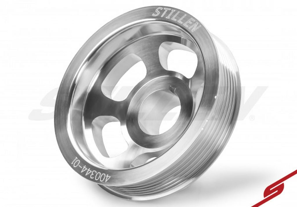
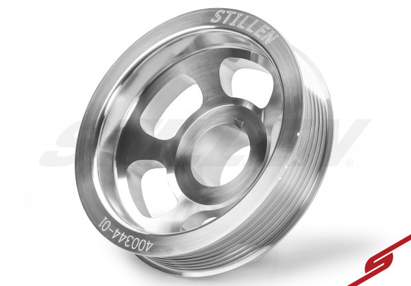
STILLEN has long manufactured precision pulleys for our supercharger kits. We have used this expertise to produce a new line of high performance crank and accessory pulleys.Each pulley is machined from 6061 aerospace grade billet aluminum with a bold new design to maximize performance, strength and minimum weight. 304 stainless steel sleeves are used for main seal contact points for durability. Stock timing marks are maintained and keyways are precision broached. All pulleys are CNC turned, milled and balanced based on computer generated designs. Up to 80% lighter weight than stock steel and up to 10% lighter than other aftermarket pulleys, we’ve seen power gains of up to 10+ HP at the wheels.Both underdrive and stock diameter applications available for most popular Nissan / Infiniti vehicles.

Product Features

  • Underdrive Crank Pulley
  • Billet Aluminum CNC Machined at STILLEN
  • OEM Pulley Weight: 4.32 lbs.
  • STILLEN Pulley Weight: 1.00 lbs.
  • Approximate Underdrive: 20%
  • Shorter Belt Required and Sold Separately
  • Not CARB Legal **Not For Sale in California**
I had been very against Underdrive pulley installation in the past. On my previous vehicles, this instal would mean that the harmonic damper was removed, and vibration and engine wear were increased. I had also seen limited improvement or gains from the mod, and felt it was purely aesthetic while potentially harming the engine and limiting alternator output.

Then I found that the VG 3.5 has an internal damper and the crank pulley is only a pulley. I have read arguments that the delrin insert in the stock pulley helps act as a damper. Based on my knowledge of the insert material, I didn’t see this as a concern.

Underdrive/ light weight pulleys work by reducing rotational mass. They do not add power to the engine. They do, however, reduce what is known as drivetrain losses. If less power is needed to spin the pulley and accessories then more power is available to be sent to the transmission. What that means is that my Engine HP did not increase at all. WHP will go up though.

I have been looking for mods to add, that don’t require taking the engine apart. I picked up one of these pulley and belt combos from the classifieds as NIB, for a much better deal than new from Stillen. I was very skeptical that this would work, but for the fairly small amount of money involved I figured I would try it.

I had my dealer install this. Generally I do the installs myself and document them for the forums, but I was feeling lazy and the dealer price wasn’t that out of line. My dealer charged $157 to install the pulley and new belt. This involves removing the wheel and fender liner, the starter, and then the pulley itself. Book time is 1.5 hours.

Impressions:

First thought: Interesting.
Second thought: the throttle limit till 30mph really limits this car.
Third thought: holy crap, this actually worked.

When not really on the gas, and at lower rpm this isn’t noticeable. When I am on the gas, above 3k rpm, there is an increase. Rule of thumb is that 5hp is the smallest increase that is registered on the butt dyno. I fully believe the 10hp claim, and feel this probably added as much as my RacingLine y-pipe. The engine does not seem to rev faster, and I attribute that to the transmission. The car does accelerate better, and I would say slightly smoother as well.

$135+$43= $178 
Installed by dealer would be $335.

Is it worth that? Potentially. I am very happy with this mod. Knowing what I know now, I would probably do it again, and have no problems recommending this to everyone on the forum. If you are looking for a fairly cheap power adder, and for one of the few things available for this engine, then this is a very good option.


Loading

Member Credit: MaximaDrvr

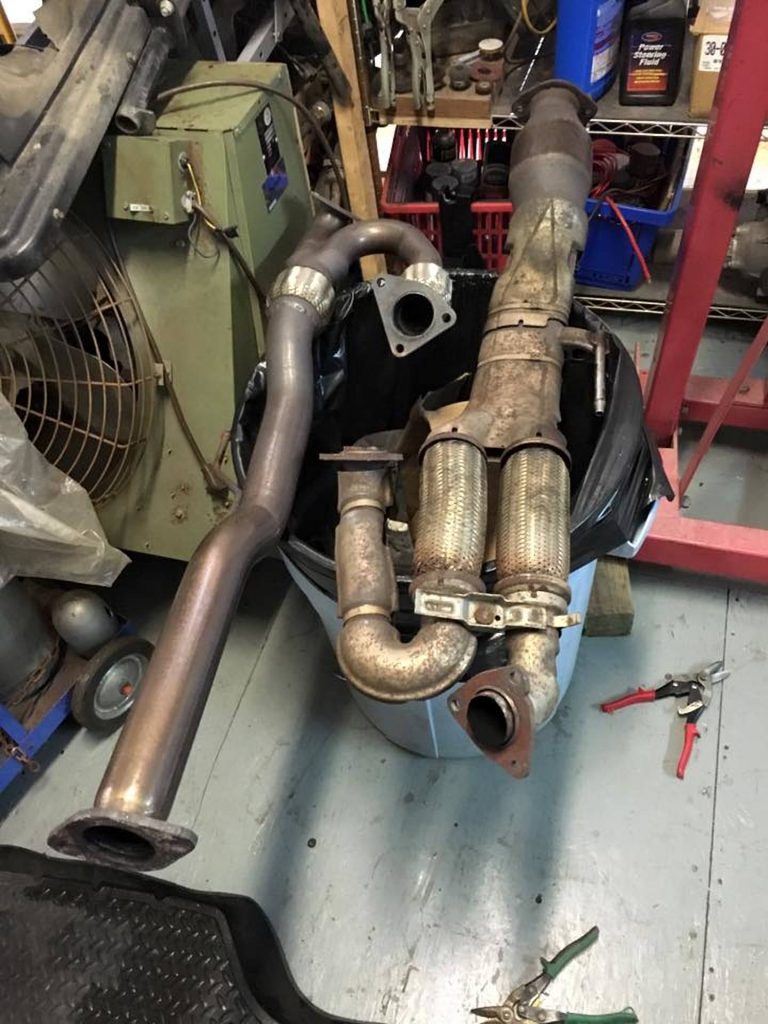
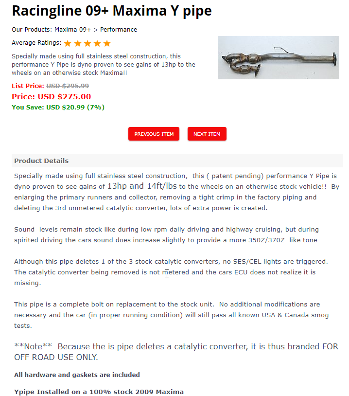
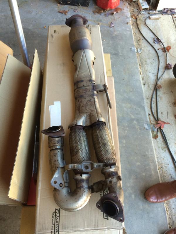
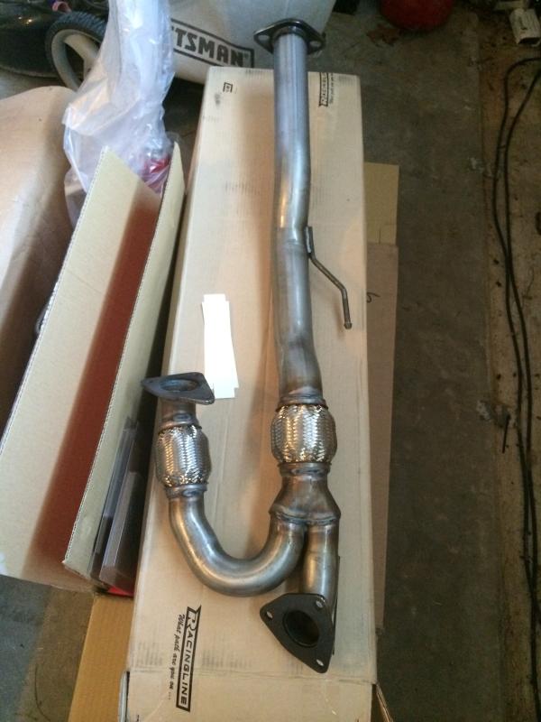
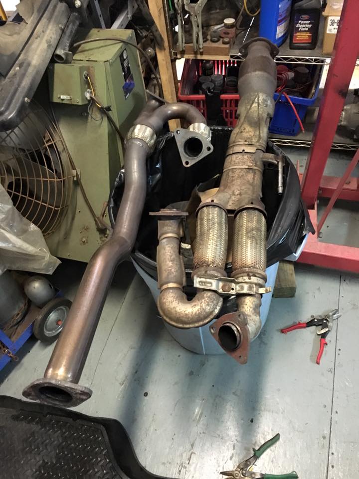
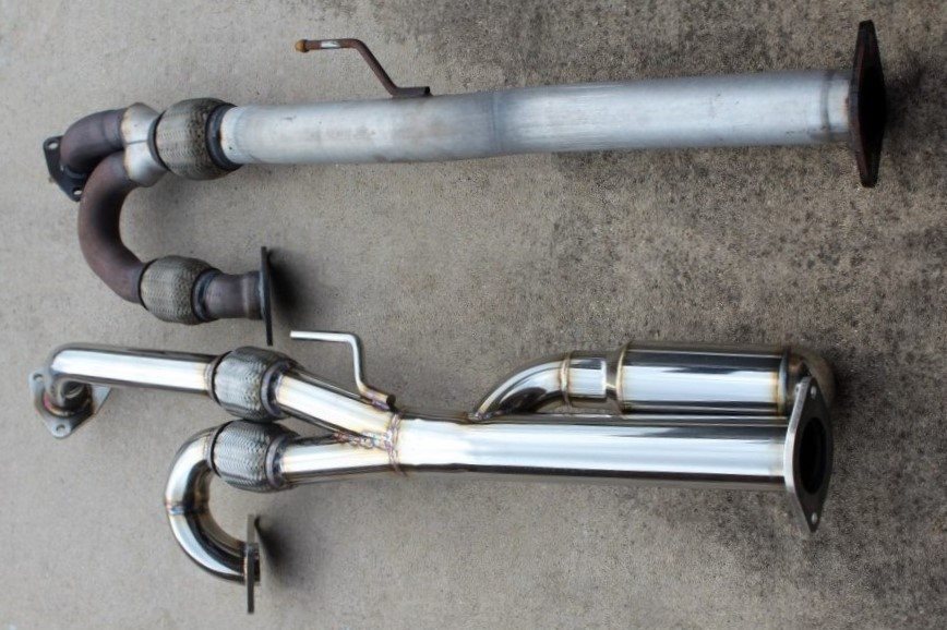
The factory pipe is about 1″ thick after the flex pipe section. The tight u-bend is significantly more restrictive than the larger bend, and the diameter of the pipe is much more consistent.  When ordering, you will need to get the gaskets, either from them or a parts store.
You will also need to go to the hardware store and pick up the following:

  • 2x 10M-1.25 x30mm
  • 2x 10M-1.25 nut
  • 2x 10M lock washer

The factory has studs to the mid pipe, while the RL pipe just has holes.

Name: C14D35F3-AD14-48C6-ADA8-51FB2448945E_zpsbwmtin9l.jpg Views: 140 Size: 68.8 KB
Name: DCF4B551-348C-4E0E-9EF9-3B050C9E6842_zpsqnuf3wyk.jpg Views: 138 Size: 56.2 KB

Racingline vs Motordyne

Video Clip

Loading

Member Credit: Stillen

Tools/Materials required:

  • Assorted wrenches/sockets
  • Pulley puller
  • Pry Bar
  • Torque wrench
  • Anti-seize
  • Factory repair manual
  • New belts (Gates K070653)

Notes: Please refer to the factory service manual for additional information on removal of additional items.

Remove the crankshaft pulley as follows:

Step 1. Disconnect the battery, raise the front of the vehicle and support with jack stands.

Step 2. Remove the passenger front wheel

Step 3. Remove the splash shield covering the crank pulley and remove drive belts per factory manual.

Step 4. Remove starter motor and lock the ring gear in place.

Step 5. Loosen crankshaft pulley bolt until it is ¼” from the surface of the pulley. Do not remove crankshaft pulley
bolt completely as it will be used as a supporting point for puller.

Step 6. Using a suitable puller, remove the crank pulley.

Install your new crankshaft pulley as follows:

Step 1. Lightly coat the inner diameter of the crankshaft pulley with anti-seize. Install crankshaft pulley, taking care not to damage front oil seal.

Step 2. Holding the ring gear, initially tighten crankshaft pulley bolt to 33 ft-lbs.

Step 3. Place a paint mark on the crankshaft pulley (a) aligned with the one of the angle mark on the crankshaft bolt (b). Tighten the bolt until it has turned 90 degrees and the next mark on the bolt is aligned with your paint mark.

Step 4. Reinstall starter, new belts (tightened per factory manual), splash shield and wheel. Lower the vehicle and reconnect the battery.

Step 5. DONE! New belts will need to be re-tightened after a couple of hundred
miles.

Loading

Member Credit: MaximaDrvr

I am completing this write up to help people save some money. You can probably buy all of the needed tools for what the dealership would charge. This was an over $400 quote for each side. Generally, you will replace these in pairs, but it is not absolutely required. I have 150k miles on my 09.

I purchased replacement assemblies from Rock Auto. The bearing assemblies were $154 shipped for the pair (TIMKEN HA590252). I would recommend new cotter pins as well, but you can make due with the old ones if necessary if you don’t break them on removal.

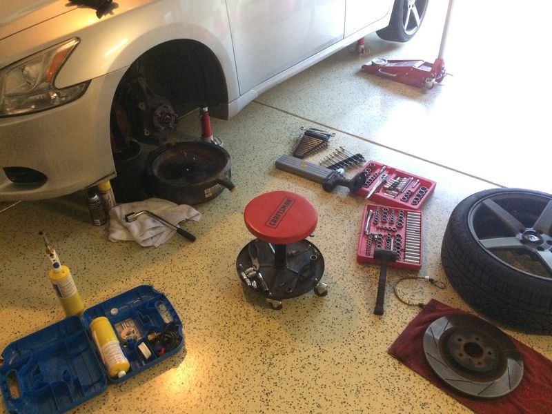
This is a fairly easy replacement as far as complexity, but it is a critical component to your car. I would recommend having some mechanical knowledge and plenty of time if you have not completed something like this before. This took me 3 hours with taking pictures, and an hour of letting penetrating oil soak in. I would say it could be done in as little as 1 hour, or as long as 6 hours if you have never done anything like it before, or need to let the penetrating oil soak in.

I was a mechanic in a previous life and had all of the tools required.

You will need:

  • 32mm socket for the axle nut
  • 22mm sockets for suspension nut/bolt
  • 18 and 19mm wrenches and sockets
  • You may need some additional sizes that I am forgetting.
  • 10mm (I think, may be. 11 or 12) for the abs/speed ring sensor
  • Breaker bar
  • Impact gun
  • Penetrating oil
  • 8″ pry bar
  • Rubber mallet
  • Ball peen hammer
  • Needle nose pliers (to remove and replace cotter pins)
  • Wood
  • Bungee cord
  • Sandpaper or scotchbrite pad

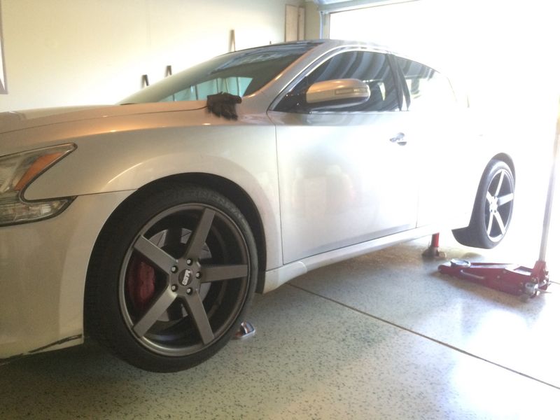
First, you need to properly jack up your car and place it on stands. Then remove the wheel on the corner you will be working on.

This is the 32mm nut and cotter pin

Remove the brakes. You need to remove the two bolts holding the caliper carrier to the knuckle. You do not need to separate the caliper and carrier.

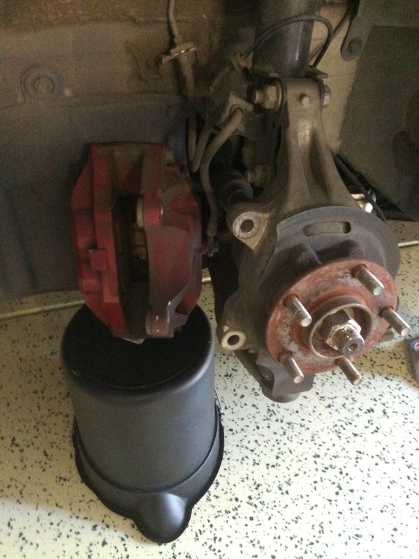
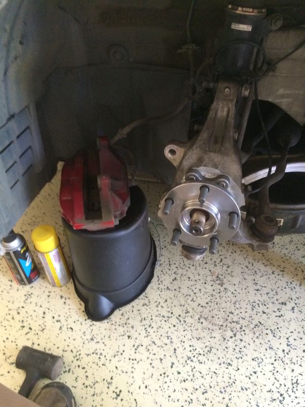
Then you can take the rotor off and set it to the side. You can then use the short pry bar to remove the brake line clip off the strut to get more room. Set the caliper to the side, but do not hang it from the brake line. I set it on top of a small bucket.

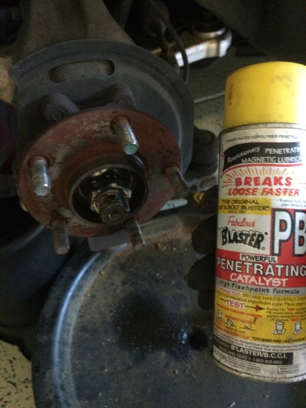
Once the brakes are off, I sprayed the axle nut with penetrating oil. I put an oil catch can underneath to not stain the floor. I also sprayed a bit of oil on the bolts between the knuckle and strut. I also removed the cotter pin at this point.

You then need to remove the axle nut. You can try a breaker bar, but you most likely won’t get far. An impact gun will be your friend. My electric gun wasn’t quite enough and I had to break out the air impact gun.

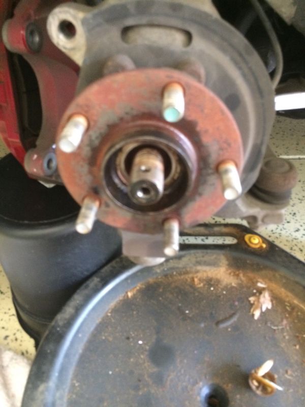
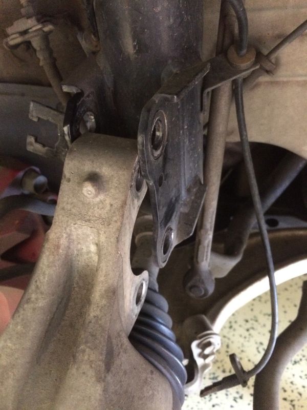
The axle nut removed. You can also see the tie rod end in the lower right. This also has a cotter pin that will need to be removed. You will remove the pin, nut and washer, the carefully tap the bolt up to remove the tie rod from the knuckle. You should also remove the abs/speed sensor at this point. It is the small bolt on the side of the knuckle. Just tuck this out of the way.

You will also remove the bolt for the lower ball joint. This must be fully removed for the shaft of the ball joint to be removed from the knuckle in the next step. You will also remove the two bolts holding the knuckle to the strut.

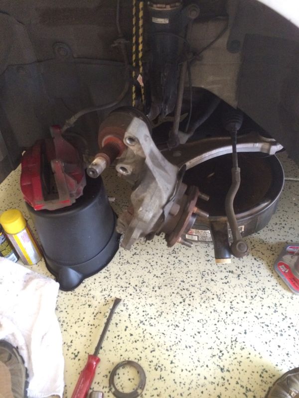
You then need to remove the axle from the hub. This should slide out fairly easily, just by wiggling and pulling the knuckle outward while pushing in on the axle. I then spun the knuckle 90 degrees, and hung the axle to the side with a bungee cord.

All that should be left holding the knuckle in place is the ball joint. Use the pry bar to spread the joint around the ball joint rod. This can be achieved by placing the pry bar in the notch, and tapping it in with the mallet. Then you should be able to lift the knuckle off the ball joint.

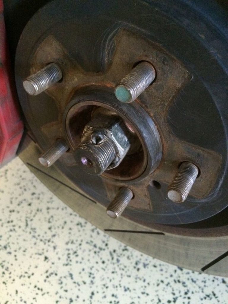
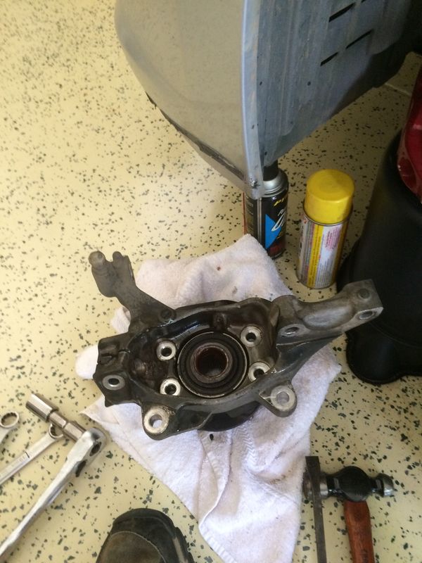
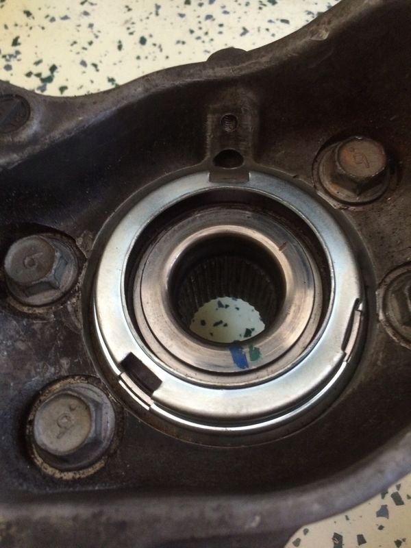
You then need to remove the 4 bolts holding the hub and bearing to the knuckle. You will also remove the dust sheild on the back of the bearing. This will just pop off with a screw driver. Take note that one of the notches in the dust cover lines up with the hole for the abs sensor.

Now it is time to remove the hub assembly.

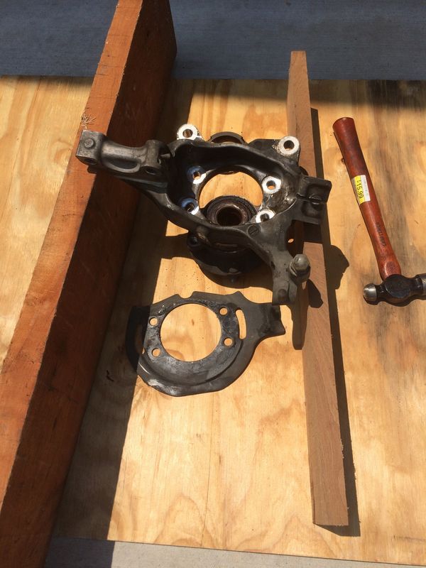
Place it on the wood blocks so that the hub can drop free of the knuckle. Then use the hammer to knock the assembly free. Take care to not hit the knuckle around where the bearing slides in.

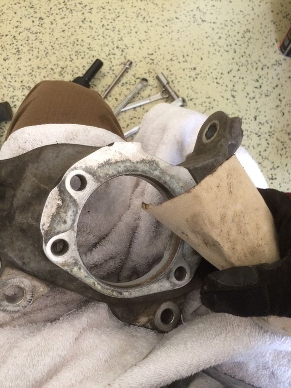
Now you need to clean up the bearing surface. Use you sand paper or scotchbrite to clean up the inside and any places with corrosion.
Now you can reassemble the knuckle and hub. Place the hub in the knuckle, lining up the bolt holes. You can use the 4 bolts to pull the hub into place. Tighten them by hand in a circular manner, not just one at a time. These should be torqued to 93ft.lbs, or really tight with a 3/4″ bar.

Then place the dust cover with one of the notches aligned with the abs sensor hole.

Now we put the knuckle back.
Slide the axle back into the hub, then slide the knuckle back onto the ball joint.
Then push the top of the knuckle back into the strut and put in the two bolts.
Then put the tie rod end back into the knuckle.

Put the abs sensor back in place and tighten the bolt.
Place the bolt back into the knuckle for the ball joint and tighten.
Place the washer and nut in place on the tie rod and tighten. Then replace the cotter pin.

Put the nuts back onto the strut bolts and tighten.
Place the axle nut onto the axle and tighten. This should be 136ft.lbs. or, really tight with a breaker bar. Then replace the cotter pin.

Next we put the brakes back together.
Put the brake line in place on the strut and replace the clip.
Put the rotor back on the hub, then put the caliper assembly back in place. Tighten the two bolts that hold it in place.

Now you put the wheel back on and you are finished.

(I made a conscious decision to not replace the dust shield. Most of you will want to make sure that the shield is back in place when you reassemble the hub and knuckle)


Loading

Member Credit: acdn

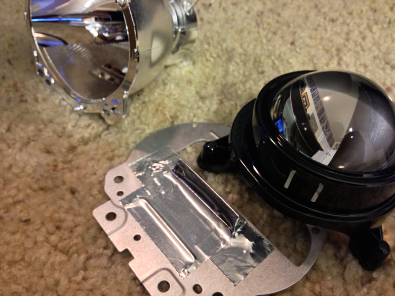
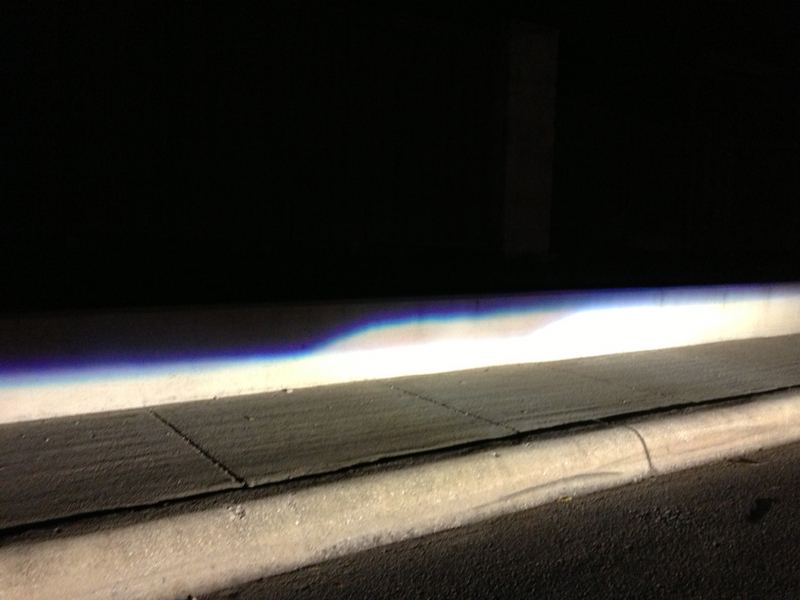
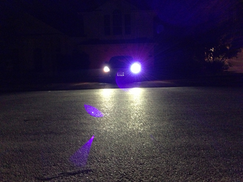
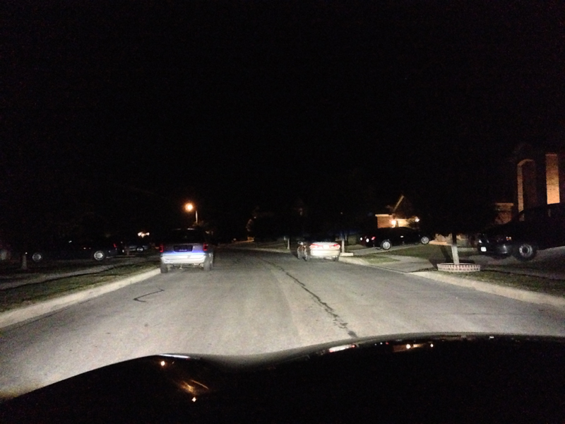
I just picked up a 2012 Maxima with OEM HIDs and I love it! I got a spare headlight to test clear lenses on before I take my car apart. I was looking at the projector and it looks identical to the RX330 non-AFS. Let me know if you have any questions. I got the product from The Retrofit Source.

Fresnel lens:

Clear lens:

Install:

The headlights are held together by 7 torx screws:

Projector taken apart with clear lens installed:

Projector back in:

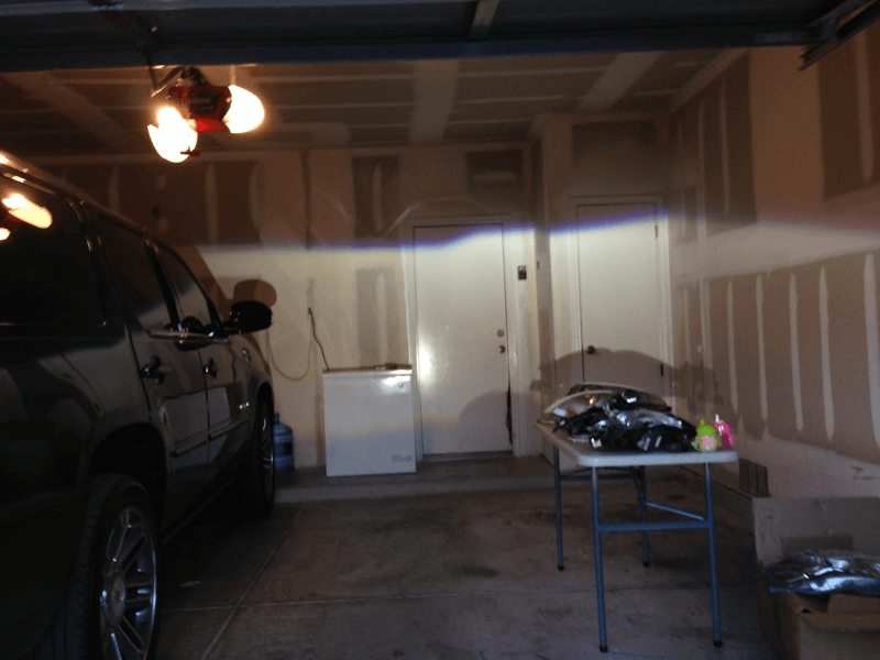
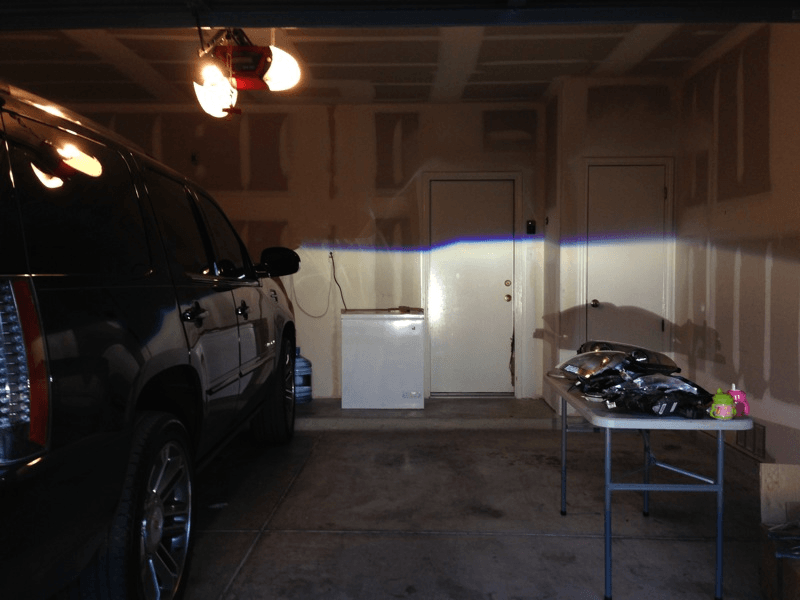
Output:

Loading

Member Credit: JETMEC

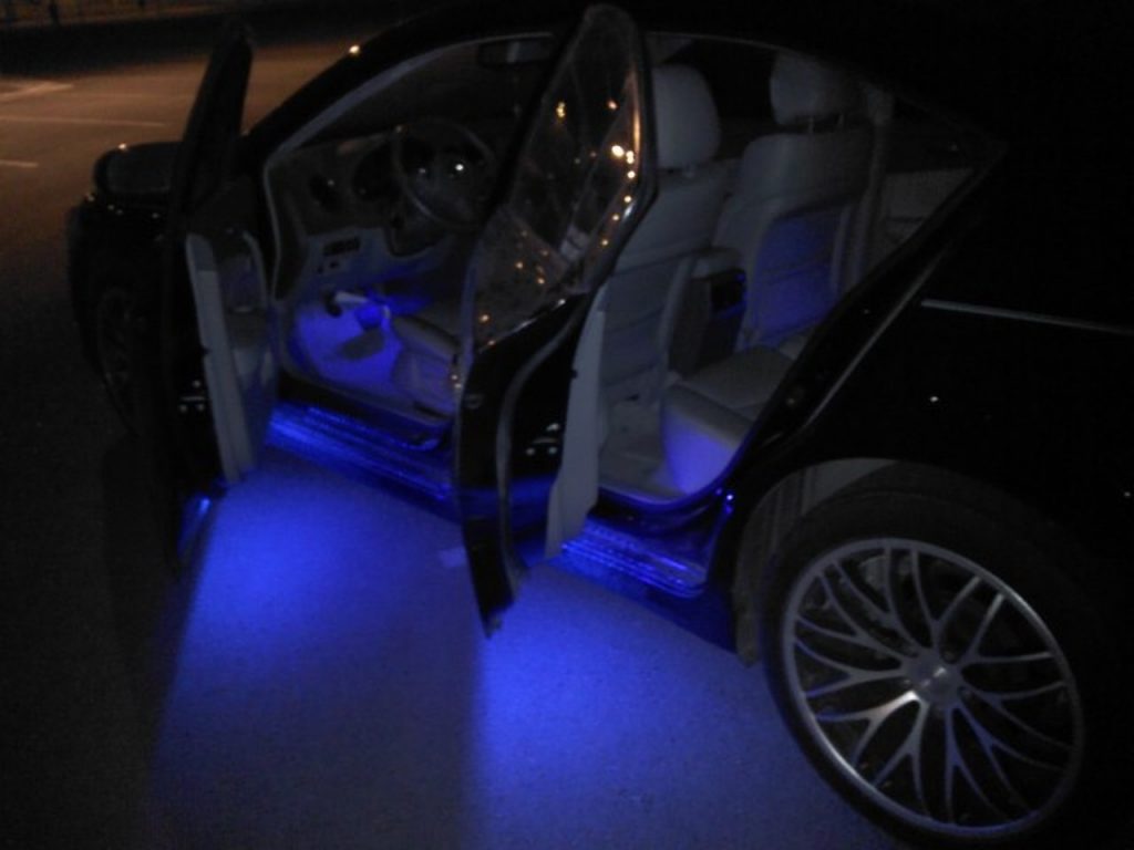
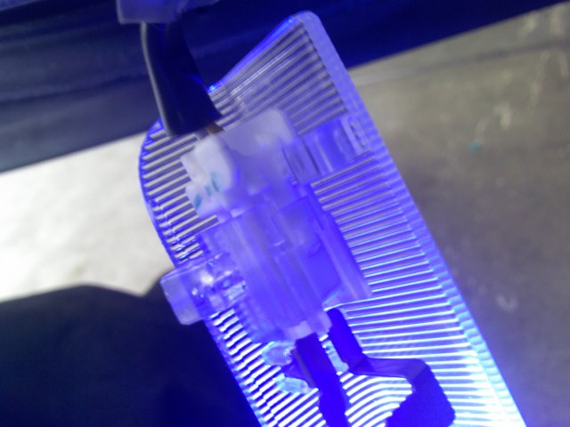
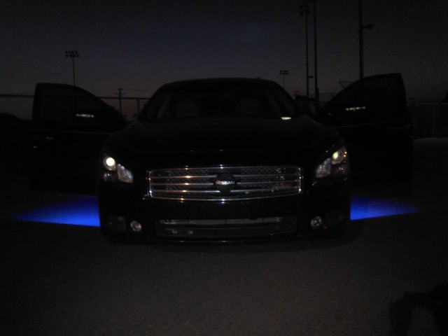
Okay guy here’s a little mod i had in my old Altima SE-R and am now bringing it to the Max family. I got all the LED’s from V-LEDS.COM ass well as the scotchlok’s for taping into the wires. Here is the mod, sorry for the crappy cell pic.

Materials/Tools

  • 2 24in LED strips (front) your’e color choice
  • 2 12in LED strips (back) your’e color choice
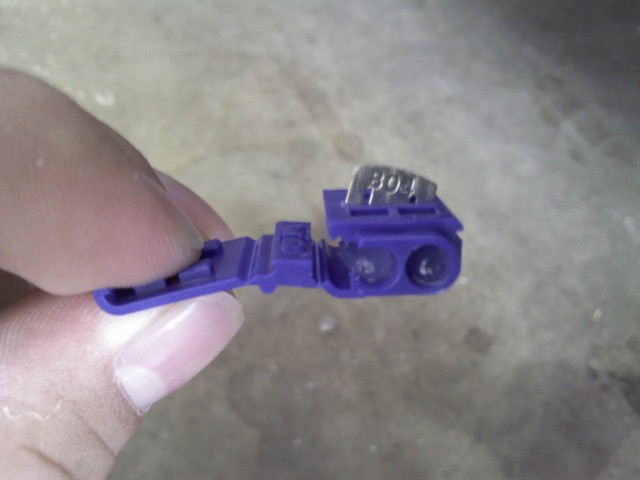
  • 4 3m Scotchlok’s (they come in pairs so 8 total)
  • Wire cutters/pliers
  • Knive/cutting tool

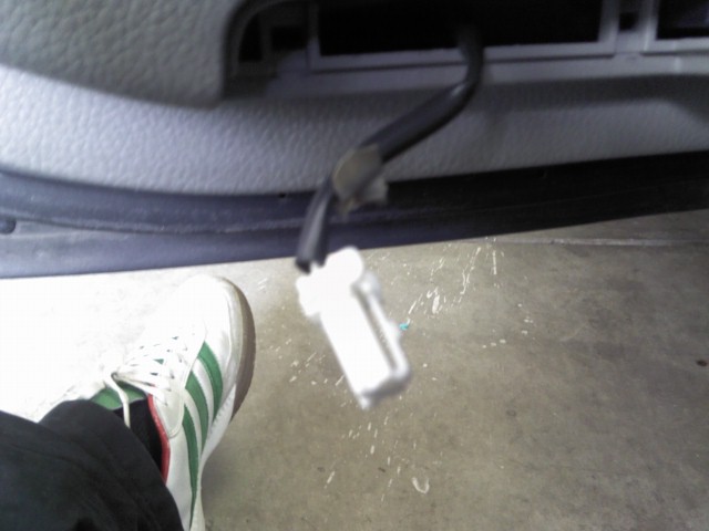
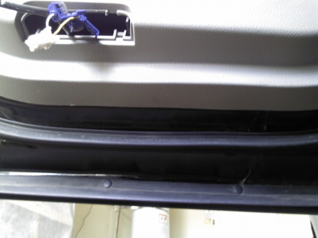
Step 1: So i started off with the rear ones where you will use the 12in strips. First pull out your’e step light like so.

Step 2: Disconnect the step light from its plug.

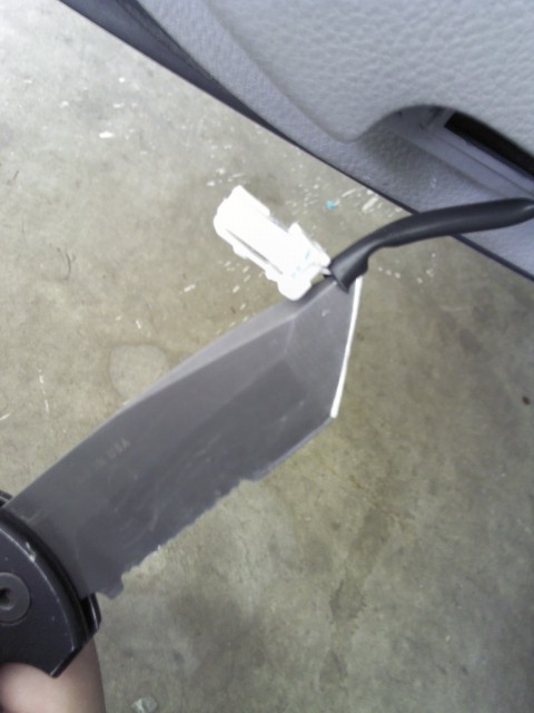
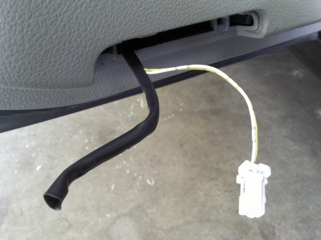
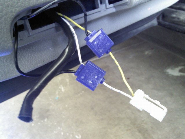
Step 3: So in all four doors the wires are under the black rubber covers. You will Have to cut them to expose the wires.
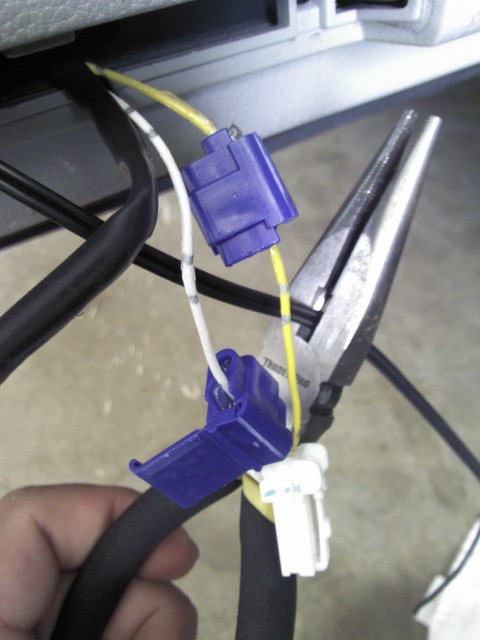
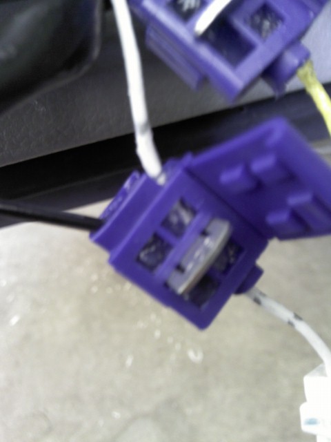
Step 4: Now you will start taping into the wires with the scothcloks. the open side is where you want to put the wires from the step lights, the open end where it only goes in half way is where you will put the strip wiring later. Theres also a video on v-leds site on how to use these.
Step 5: Press down on the metal piece in the middle to snug down the wire. DONT PRESS DOWN ALL THE WAY. You still need to put in the strip wire on the other side. all you want is for it to be snug so it wont move while you do the other wire.
Note: Sometimes the metal wont cut through the wire plastic so if you want you can pre cut into the wire to make it easier to splice.

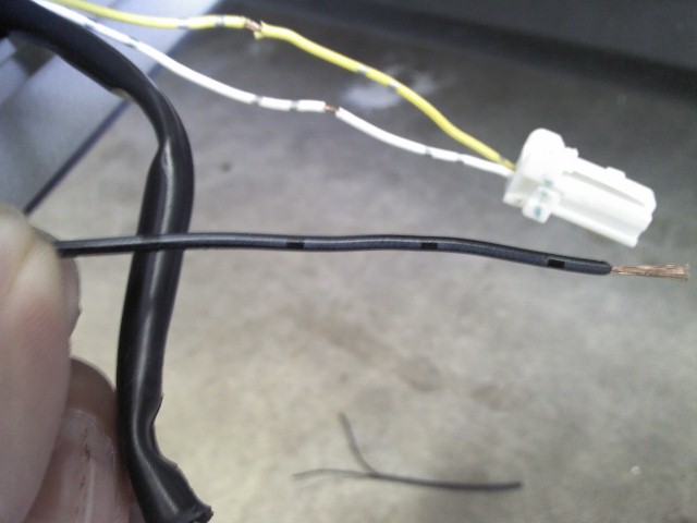
Step 6: Here is where you will put the strip, remember to clean it so you wont be sticking it to dirt. Also this is where you will feed the strip wiring from.

Step 7: Now give yourself enough slack on both ends but cut the strip wires to align to the step lights

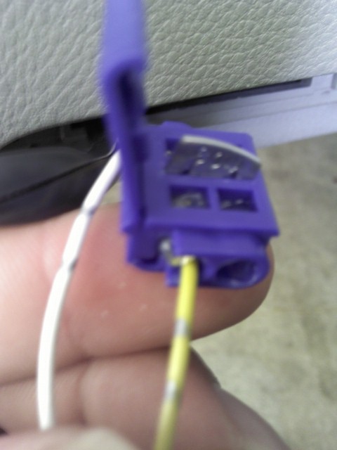
Step 8: The wire with the gray lines is the wire that goes to the yellow wire. The other wire with the small letters goes to the white wire.

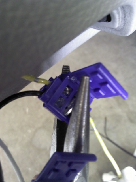
Step 9: Put the LED wires in there respective slots. Make sure you have some exposed wire before you crimp it down so that the little metal tab makes a complete circuit touching both wires.

Step 10: Before crimping down the metal tabs check to see if your’e LED lights up. If it does not MAKE SURE THE METAL TABS ARE TOUCHING EXPOSED WIRE ON ALL 4 ENDS. If it still did not light up make sure the wire with the gray tabs is with the yellow wire and the other with the white.

Step 11: Once they light up you may crimp the metal tab down. Make sure to do so tight so that the wires don’t come lose later on.
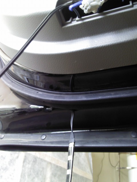
This is what you should have now with a lighted LED. You can cut of the black rubber, i did, or you can keep it, up to you.

Step 12: Stick the led to the bottom of the door now and again make sure you have a clean surface.


Step 13: Plug in you’re step light back up and place it back in its bracket, you should have enough room to fit it all back in there.

Step 14: Repeat for the other three doors.

Note: The front ones wiring was different. the LED wire with the gray tabs goes to the WHITE wire in both front doors, the other wire to the YELLOW.

Why? Beats me maybe the strips are different or maybe the car which i doubt. So again if it does not light up flip the wires and check.

Step 15: Finish and admire you’re work with a cold beer.

Here are some more pics of the finished mod. Again sorry for the crappy cel pics.

Hope you guys enjoy the mod. If you have any questions please don’t hesitate to ask. For you that do the mod, please post up pics of you’re MAX here. It will be interesting to see how other people’s color combinations look like.

Loading

Member Credit: hamzer11 & Ghozt

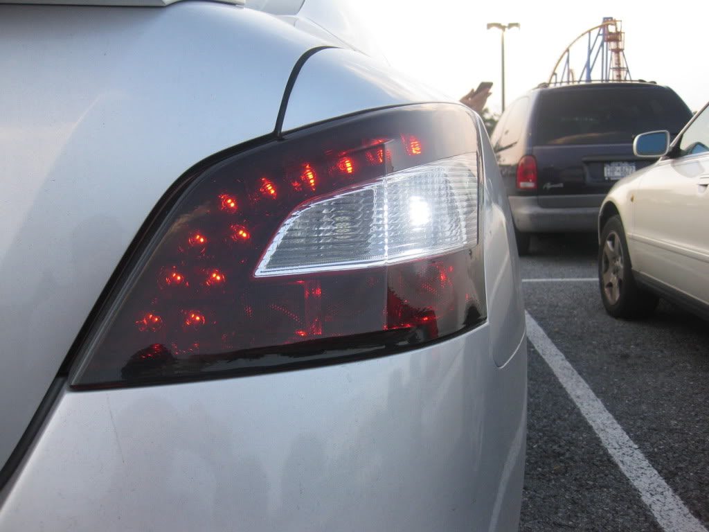
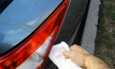
One word of caution to others: when I tried this method I broke a piece off my tail light. I noticed from comments on other forums a few others did as well. If you want a method of removing them without that risk you can get a rubber mallet and pound on the bolts that extend into the trunk until the tail lights pop out. I’ve taken them out several times this way now and it works great.


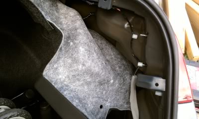
1. Remove the carpet lining. This involves removing several “push pin” things. It’s pretty straight forward if you look at it.

2. Remove the wire holder clips from the bolts:

3. Remove the 2 8mm nuts:

Once removed, shift the light out a little from that side

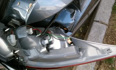
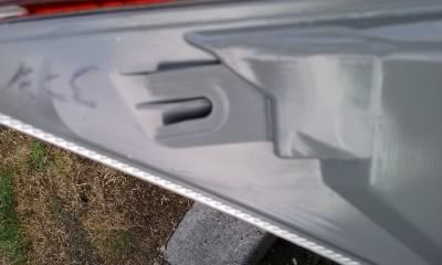
4. Carefully place a dulled (I have one that I rounded from the front for things like this) flat-head screwdriver in a towel or cloth. Wedge that near the clamping points on the light. There are two. The pictures below show the clamping pints from inside so you get an idea of where they are. There was enough space for me to get the screwdriver in and pull back while also pulling the light with my other hand. (Having someone to help pull the light is great too).

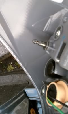
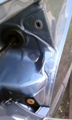
These are pins you are trying to loosen out

Here is where they go into the body

My passenger side light came off real easy but the driver side took some more effort. Don’t just wedge the screwdriver in one spot and pull. Keep creating a little space then wedge the screwdriver at a higher or lower spot and slowly loosen out the light.

5. Pull the light out and rest it in the empty space

6. Remove and replace the bulbs you want. (no pictures – very straightforward)

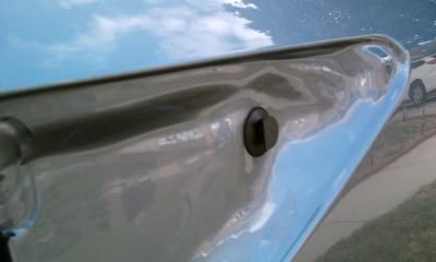
7. When replacing the light make sure to slide the guide at the corner of the light on the the pin. Here are pictures for clarification.
Additional Tips by: Nbpatel44

Make sure you remove the carpet floor and cardboard covering your spare tire. Fold any un-removable carpet into the front corner. Then, you have to remove the two big “push buttons” as I call them, for the entire rear plastic plate that hugs the back bumper on the inside. Then remove the three smaller push buttons along the edge of that same plastic piece. You’ll notice some bolts right here the trunk latch is, don’t touch those. Then to remove the actual plastic cover, you need to LIFT the pins out of their slots (there are four flat pints that point down into the ground). Then the cover should come off. I had to really rip this thing off by pulling towards myself. It seems the pins are slightly angled. You might need to pull hard to get the pins to release. You’ll see that these things aren’t really pins as they are like “stakes” that grab onto the metal frame.

For these push buttons that exist all over the carpet lining, they should involve taking a screw driver and prying up the “pin” and then the entire button afterwards. For installing, the pin cannot be pushed in when trying to push them. I used my thumb to create a small gap as I push the base of the button in. Re-installing is super easy, so shouldn’t have to force it too much.

After taking off the plastic cover hugging the rear bumper, start removing the push buttons around the edge of the carpet lining. I removed enough that I could really peel it back and gain access. There is a major plastic rivet I believe that points directly up on the trunk ceiling. That one was the hardest one to remove by far. It isn’t the same as the others, and mine was grey (if that makes a difference)

Then once you have access, pull off the plastic clips holding the wires to the bolts. Should be easy with a screw driver. On those same bolts, there should be a black nut with a wide flange, take those two off.

*Important part*
You need to unplug the wiring harness from the car. It is farther back towards the front of the car. Depress the “tongue” on the wire connector as best as you can with a screw driver as you pull (if you depress really hard it should be easy to remove – just wiggle). Sort of like an ethernet cable. The wiring connector that is not originating from the tail light should be fastened to the metal part of the car, so don’t rip that off.

Now that the wiring connection has been taken off, you’ll notice there is a rubber seal around where the wire enters the metal frame of the car from inside the tail light housing. You need to use a screw driver (or your hands) to push that rubber seal completely into the hole, making it disappear so the entire wire can be removed with the tail light. Otherwise, when you pull the tail light out, the rubber seal will stop the cable from exiting and pull on it unnecessarily.

Now you’re ready to pull the tail light out. The two bolts that are closest to the trunk opening (the ones you removed the nut and wiring clips from) can be hammered on (moderately hard) so the tail light starts to push out just slightly. I just placed a folded towel in front of the bolts and used a regular hammer. Without the towel might be okay, but it is super loud obviously. These two bolts are actually your tail light assembly so they need to be completely pushed out. I actually couldn’t hammer them out completely. I got about halfway.

Then I took a screw driver and wrapped a towel around the edge. It was a sharp screw driver so I didn’t press it too hard around the tip. Because the tail light was already slightly removed, I was able to go to the very front corner of the tail light and just lightly push it out and pull on the tail light assembly. It came out so easily. The trick to not cracking the light is not to pull with the screw driver until you’ve made progress with the hammer.

First thing I did was feed the wire from the new tail light into the car and pushed the rubber seal back through (you’ll know what I’m talking about once you see it).

Then I lined up the tail light with the two bolts, one corner slider slot, and two metal pins that are completely hidden the whole time until you remove the tail light.

I pushed in, it mounted well, I screwed the nuts back on, connected the wiring harness, did a quick lighting check to make sure I didn’t receive a faulty product. Then I peeled the carpet lining back, did the top ceiling rivet first, then the two buttons near the wheel well, then the rest near the trunk door. Then I popped on the plastic piece that covers the entire rear part of the car. Remember to line up the four flat pins that face down. Once they slide into the pin slot (you might need to pull towards you as you push down), then put the five push buttons back on (remember two of them are huge).

Done! Now that I know how to do it, it seems really easy to replace bulbs/entire tail light. I actually saved the wiring part of my old tail light (cracked) and will trash the housing.

Loading