Alot of people dont think very high of doing this mod but if your not one of them and your interested enjoy!
What you need:
( all can be purchased at you local Lowe’s or Home Depot )
1. A razor blade or scissors
2. 3M red double sided heavy duty tape about $9.00
3. 1 9 foot roll of garage door bottom seal about $10.00
Steps:
1. Put the 3M tape on the door seal.
2. Clean the bottom of your bumper where the lip is going.
3. Start removing the tape plastic and attaching your new lip. lol
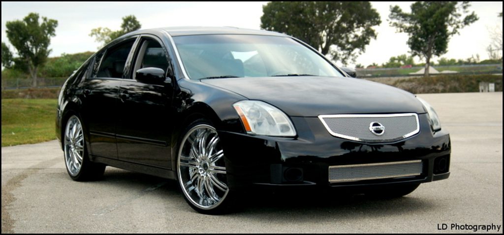
Below are the most commonly asked questions before starting this conversion. This very similar to getting the hybrid bumper which allows you to retain 2004-2006 Headlights/Hood with 2007/2008 Bumper.
“Where did you get your 2007 bumper?”
I got mine on eBay for about $50.00 on eBay, with about $50.00 in shipping. It was off a wrecked 2007.
“What about the cornering lights in the stock bumper? I would lose those, so does the 2007 have corner lights?”
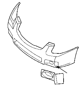
The stock 2007 does have cornering lights, but they’re in the headlight assembly. The 2007 has the FOGS down below (and we have them in the actual headlight assembly). You’d have to get some aftermarket fogs (the measurement is approximately 3.5″ x 3″, just in case you wanted to go that route. Or you can get 2007 OEM fogs, but those are always so expensive. Oh, and you’ll also have to get FINISH PANELS for the fogs. It’s the little matte plastic “covers” that go “around” the fog lights. It’s simply a cosmetic thing, and I purchased them from www.everythingnissan.com for $9.00 for both (you can also get the fogs there for a cheaper option). So that’s not an issue at all. Here’s what I’m talking about:
“Do the headlight line up?”
The headlights light up to an extent. There’s a SLIGHT gap under the light, but it’s nothing significant, and aligned properly there’s no gap at all. I’m still working on that. It’s nothing big though, and if you LIFT AND PUSH the bumper into place simultaneously, it should click in properly.
“What about the hood latch?”
This fits perfectly. No issues at all.
“How much did everything cost?”
– bumper – $100.00 (with shipping)
– contours around lights – $150.00
– paint bumper – $250.00 – paint hood – $250.00 – Finish panels – $9.00 – New 07 grille – $200.00 – 07 fog lights – varies. $70.00 – $300.00
“What needs to be modified on the hood?”
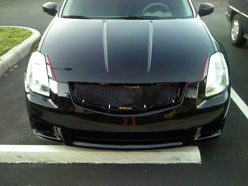
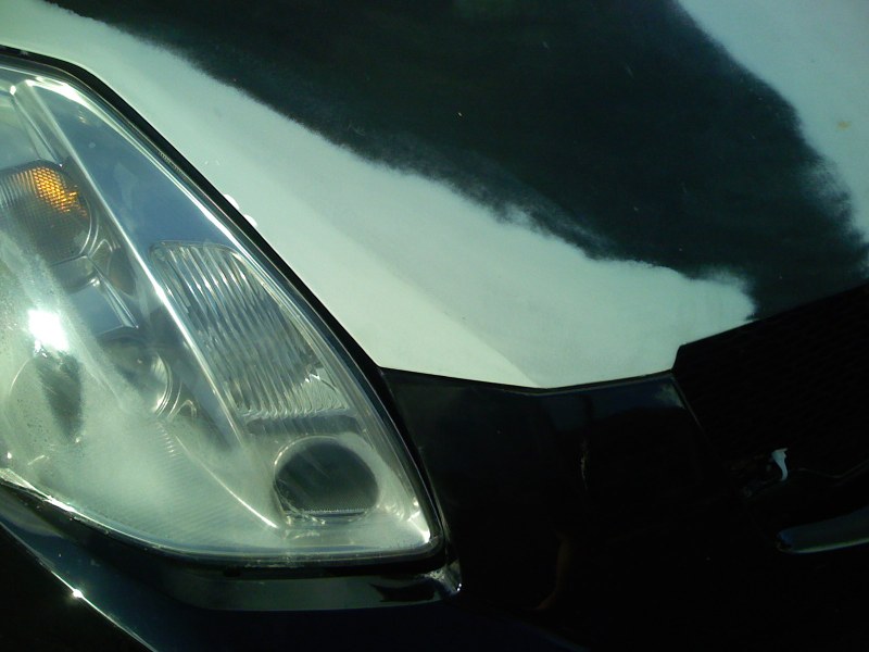
The contour lines around the lights are different from the ’07 lines. Those need to be shaped to the right alignment. The hood needs to be extended a bit in the grille opening to line up properly. I actually just added a little bondo where the grille contours need to be lined-up, so that wasn’t a big deal. Oh, and there’s a slight overlap near the lights that needs to either be shaved or banged down. My bodyshop guy banged them down since the hood is aluminum. Keep in mind, after the hood work, you’re going to have to get the hood repainted. The red lines indicate where a body shop needs to bang and/or bondo to the right shape:
Contours:
Bondo in grille opening:
Reshape passenger headlamp:
Reshape driver headlamp:
Complete re-contouring:
Finished product:
“What did you ever do with the cornering light assembly and function?”
I have not done anything with the cornering assembly as of yet. I’m still in the market for some fog lights, and Luke said he’d help me wire them to be functional as fogs, not corners.
“Could you cop the 07 hood as well, instead of messing with the contours?”
Well, it is possible, but then you’d have to cop the ’07 lights as well. OR modify THAT hood to fit the 04-06 lights. Either way a hood would have to be modified. At least as far as I can see. And if you did get the 07 lights, the quarter panels would have to be remolded too. I believe I went the cheapest and most effective route. Bumper Removal/Installation
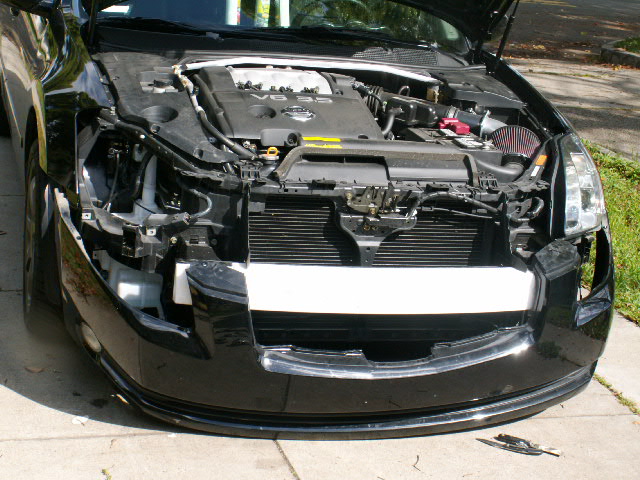
The first step is to remove the grill. The plastic fasteners are easy to remove. If you have two small flat blade screwdrivers, like I didn’t have, you put each one on one side of the center part and pull it up. Then grab it and pull the whole fastener out. Put the grill aside somewhere where you won’t step on it. Now its time to remove the whole front bumper cover. You will need a Phillips screwdriver and your small flat blades. Start on either side of the cover. First you need to have access to some of the fasteners and screws. These are hidden behind the fender well plastic covers. Remove the fasteners that hold the fender well plastic. Remove enough of them that you can pry it open to get your arm in the TIGHT space to remove the screws. Once you get the fender well trim open, there are two screws that hold the cover on. They are hard to get at, but try. Unscrew the two screws. Then go underneath and see many fasteners that hold the underside plastic tray to the bumper cover. These were harder for me to remove. But I got them undone. Now do the other side. The front cover drops down exposing the lights. These are held on by 10 mm screws. Find them and remove them. Here is a pic of the car with cover removed and one headlight out:
Perform the reverse of removal for the 07 bumper cover and voila! Fog Light Rewire/Conversion
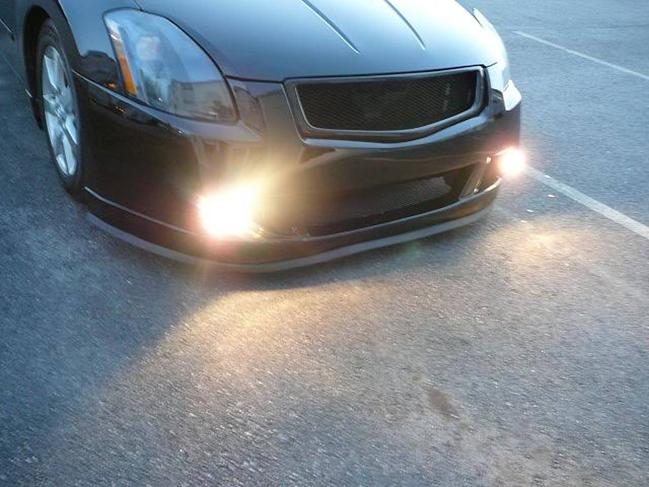
This section is for those planning to install OEM fog lights while controlling them using the factory fog light switch. After the 04-06 bumper is removed uninstall the headlights which are removable by 5-10mm bolts around the corners of the light. Once the light is removed perform the following rewire to allow the headlight fog lights to transform into an additional parking light circuit and for the bumper fog lights to now be the switch controlled fog light.
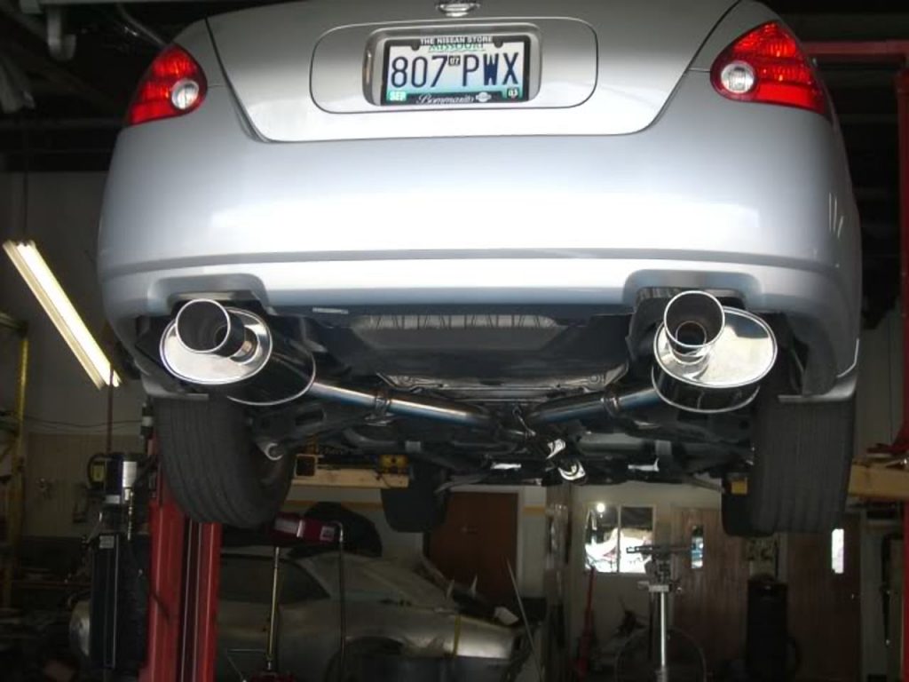
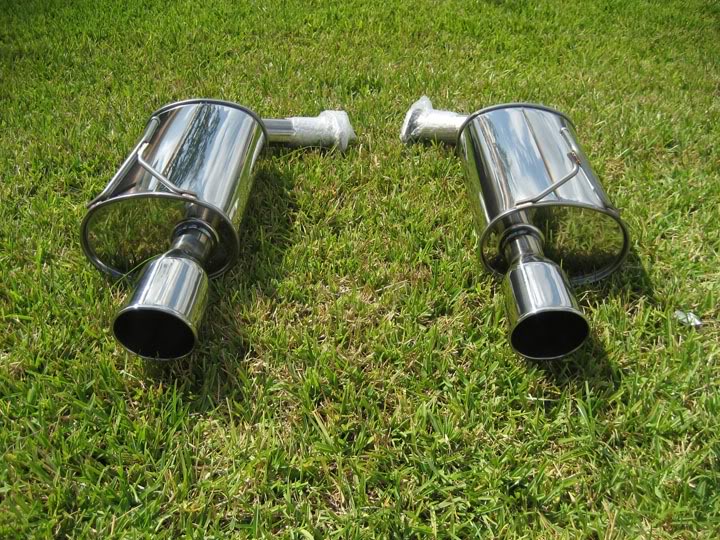
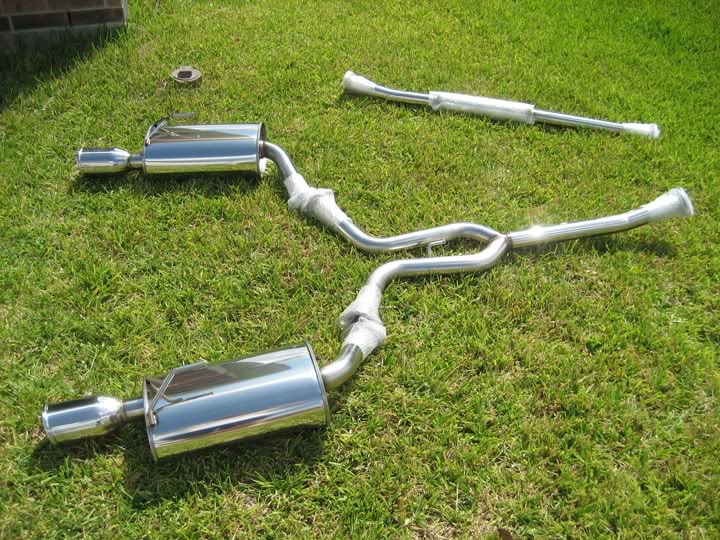
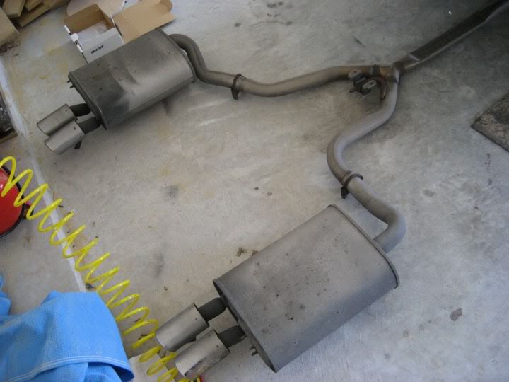
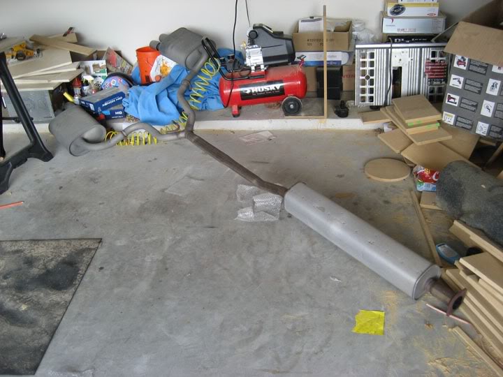
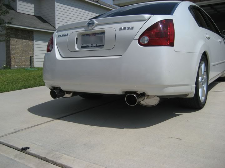
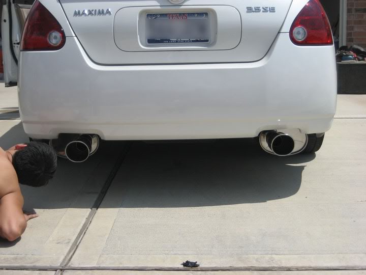
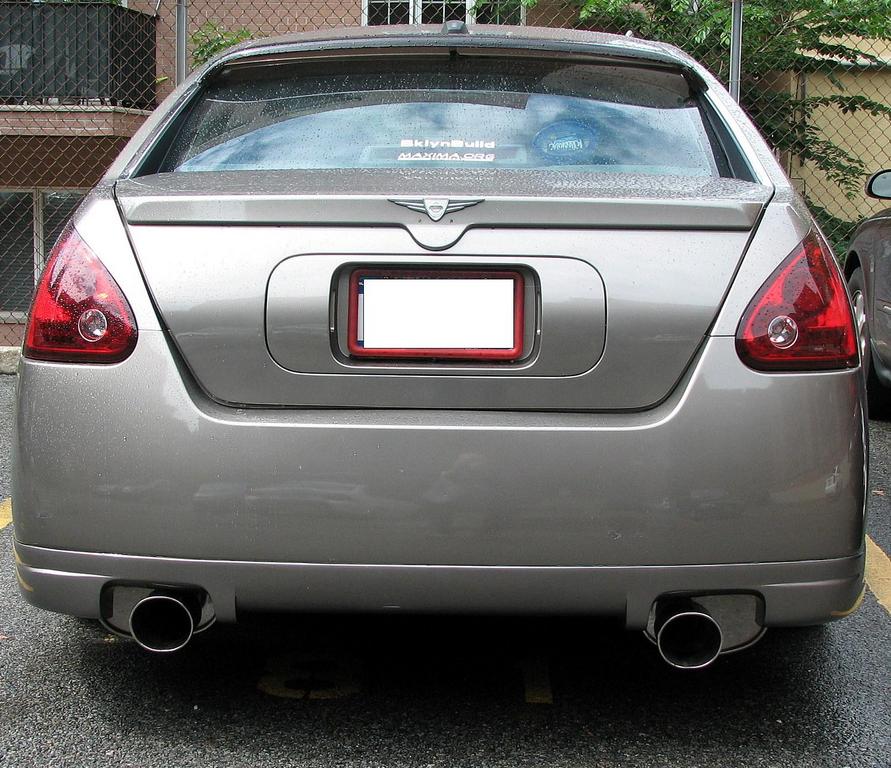
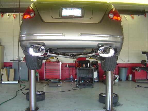
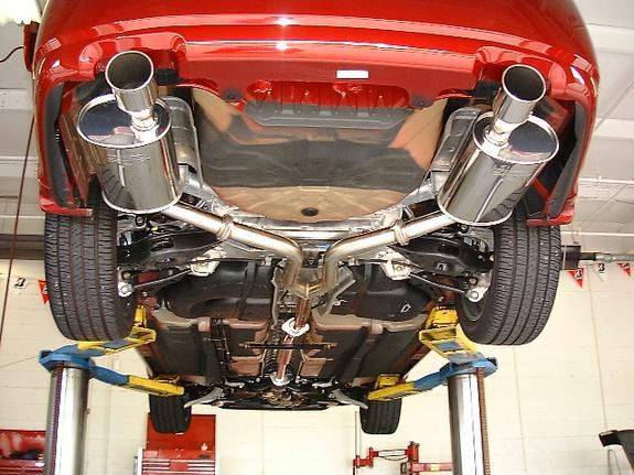
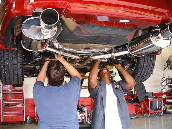
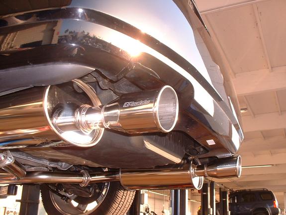
This exhaust is no longer available for sale. This is only for reference and documentation purposes. It cost approx. $900.00-$1,000 when it was available for sale. The part number was 10127021.
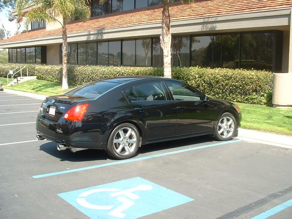
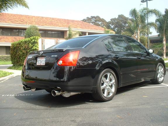
GReddy’s SE exhaust systems deliver the full spectrum of features desired in a street performance system. SE exhausts increase flow via tuned piping and larger, free-flowing mufflers for improved power, but provide discreet sound levels that won’t attract the wrong kind of attention. The exhaust note is comfortable and sporty, not loud.
All SE Exhaust are test to be well below the 95dBA standard. The new smaller Spectrum exhaust tip(s) help disguise the system from the rear of the vehicle, but reveal show-quality appearance from the side and underneath. Whether you are cruising down the road or at wide-open throttle down the track, the Spectrum Elite is ready.
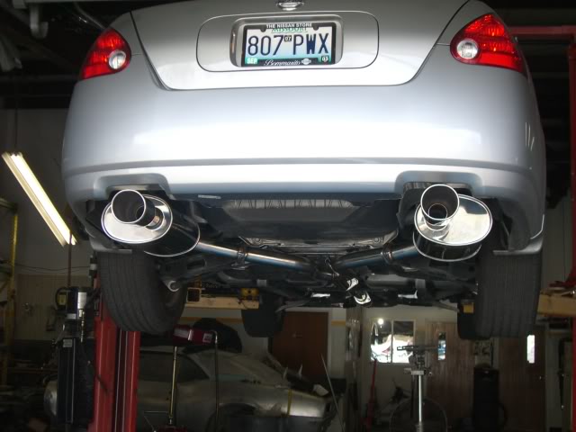
This exhaust is no longer available for sale. This is only for reference and documentation purposes. It cost approx. $900.00-$1,000 when it was available for sale.
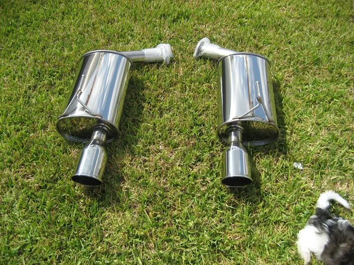
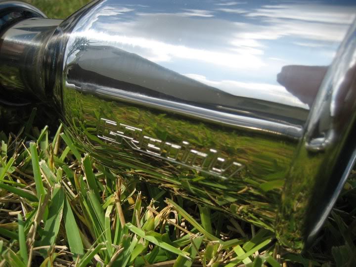
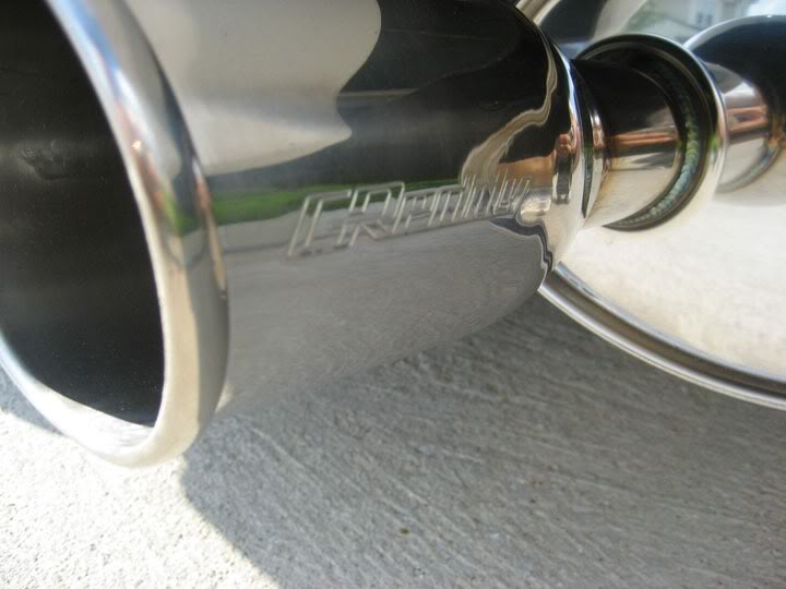
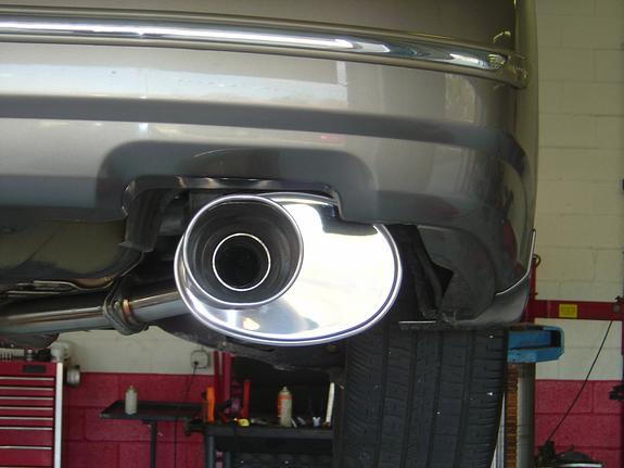
The SP2 features a 304 stainless steel muffler canister with extra strong 430 SS end caps that feature a deep, high polish. Large, high volume mufflers provide maximum flow with a deep, pleasing tone and are especially effective when used on vehicles with aftermarket turbocharger systems. The unique outer curled oval tip (115 x 110mm dia.) is embossed with the famous GReddy logo.
I looked at and sat in many many seats. I had several criteria:
1. Lightweight (under 35 lbs) – This is an easy way to drop lots of weight. The OEM seats are 65 lbs EACH.
2. High bolsters – I want to be held in by the seat. I like high side bolsters
3. Charcoal leather – To match my interior. I would have bought cloth seats, but I would have had to re=cover them in leather later.
4. Reclinable – This is my daily driver, with different people driving. I really wanted reclinable.
I chose leather seats from aa Mitsubishi Lancer Evolution 8. In this pic the OEM passenger seat is still in, but the drivers seat is the Recaro
This was a rare option on these cars. I remember sitting in an Evo with leather a few years ago and LOVED the seats. They are aggressive, but not so much so, like Brides. They arent to hard to get in and out of. In fact, the lower bolster is similar to the OEM Maxima seat. The top part is much more aggressive, like sitting in a cradle. It is much firmer than the Maxima seat, yet it forms to the body. They are incredibly comfortable.
I had Wedge Engineering fabricate a beautiful bracket and slider that fits perfectly. They used a jig from the Bride seats that Sexima (org member) had in his car.
Installation:
1. Remove the plastic covers and the 4 bolts holding the seats in.
2. Disconnect battery, and wait several minutes.
3. Tilt seat back and remove the connectors for air bag and other electronics.
4. Carefully pull the heavy seat out of the car.
5. Install the 2 ohm 1/2 watt resistor in the air bag connector.
6. Install the new seat, and bolt it down. Now is the time to install harness too if u have one.
Comparison of Maxima seat and Recaro seat:
Top view of Maxima seat and Recaro seat. Note the much deeper bolsters in the Recaro:
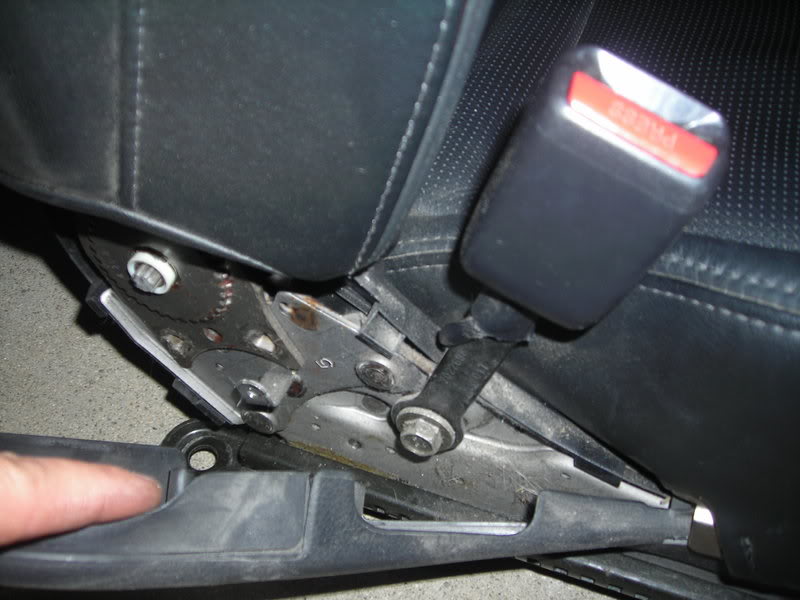
7. Remove seat belt receptor from OEM seat and install on Recaro bracket:
8. Seat installed with Sparco harness:
The seats look a bit stained but its cuz I used tons of leather conditioner. They look stock but slightly aggressive, and the leather matches PERFECTLY. I am extremely pleased with these seats.
Member Credit: THE PRESENCE, EddyMaxx & DeusExMaxima
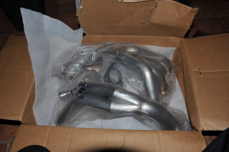
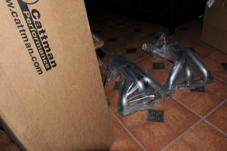
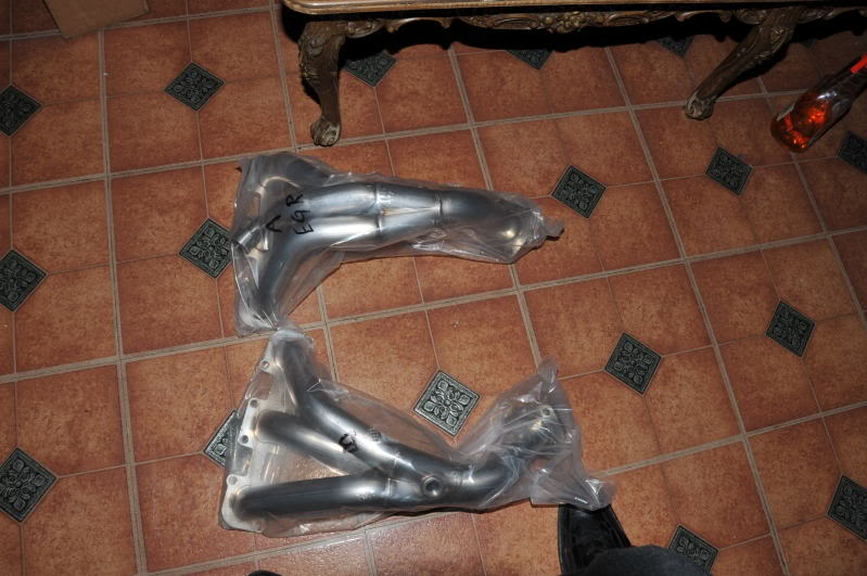
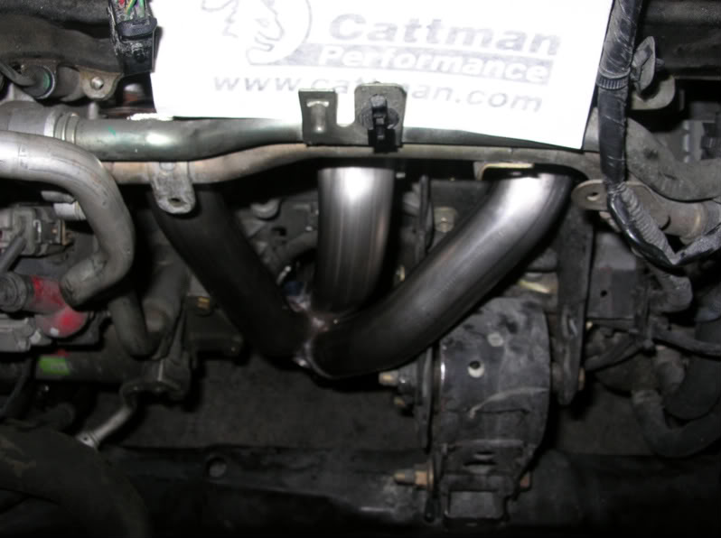
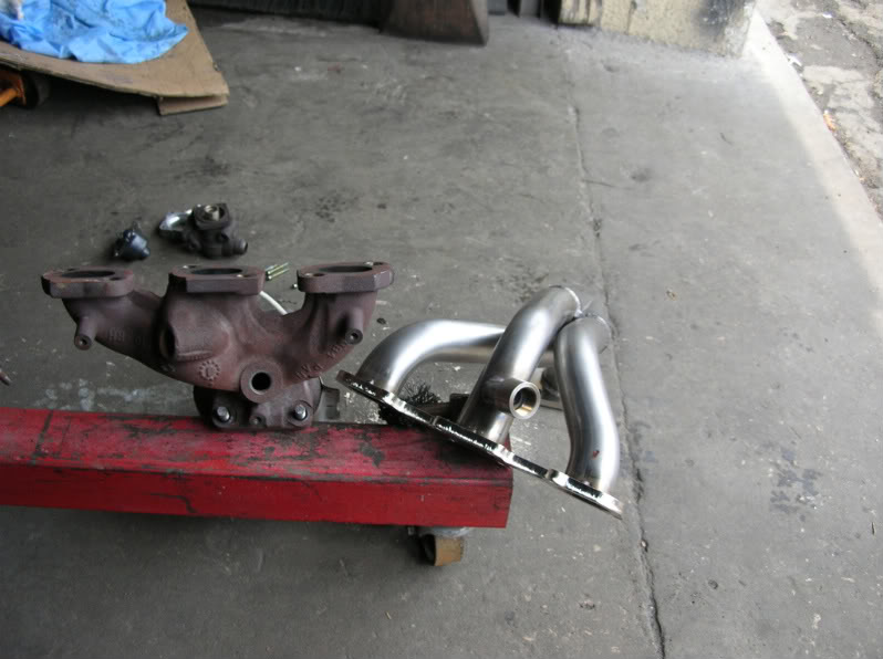
Unboxing Cattman photos from Eddy.
This is a project that I will never forget. Actually, me and my mechanic had fun with the install.
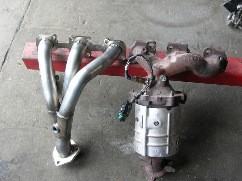
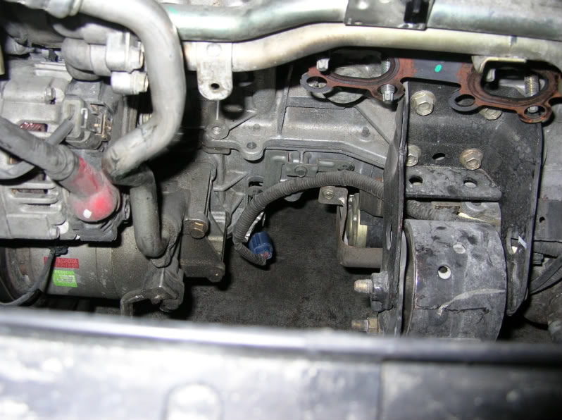
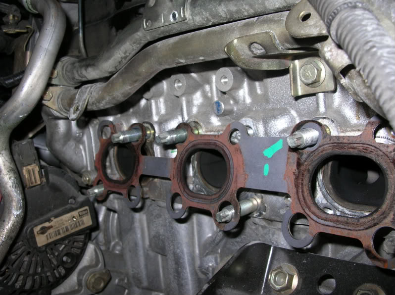
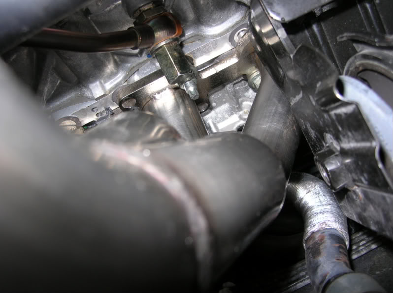
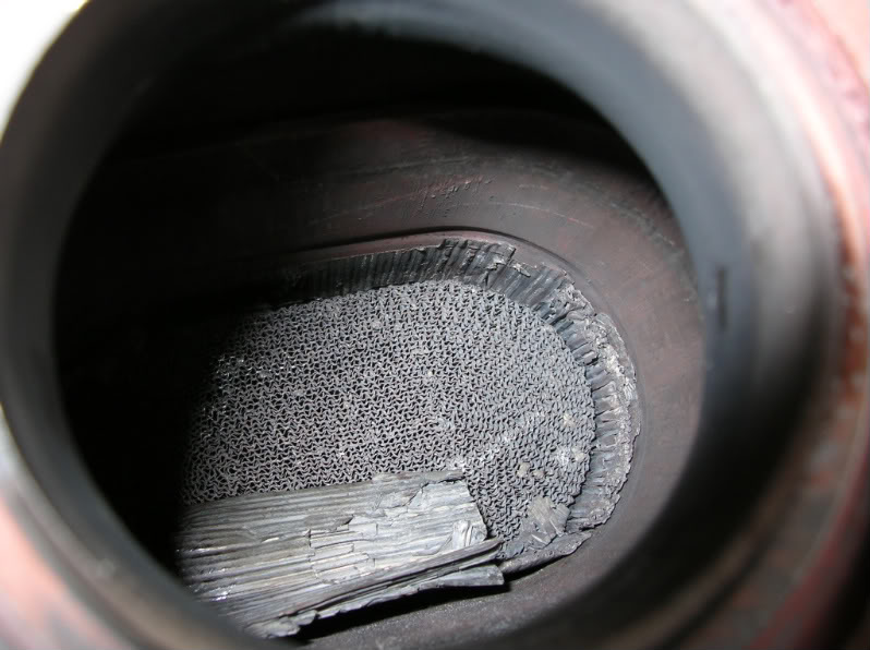
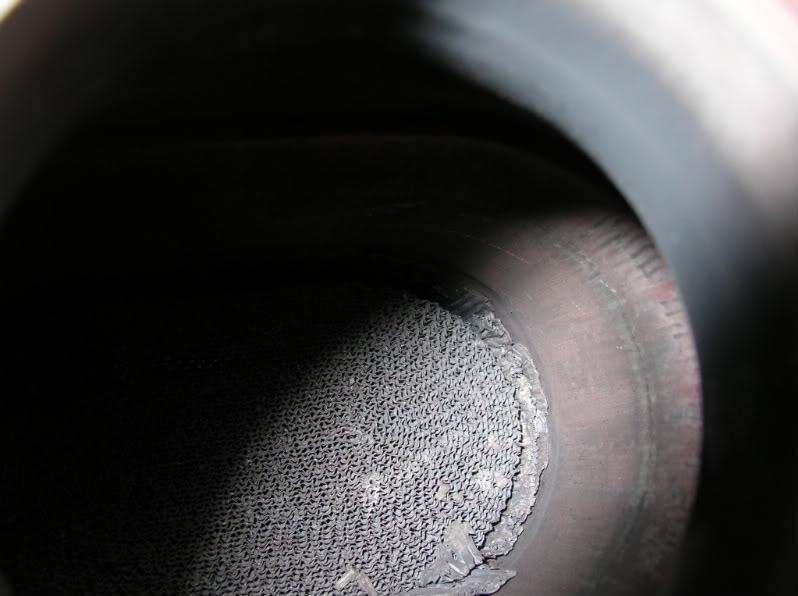
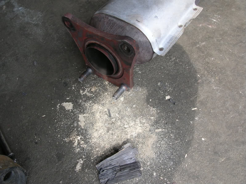
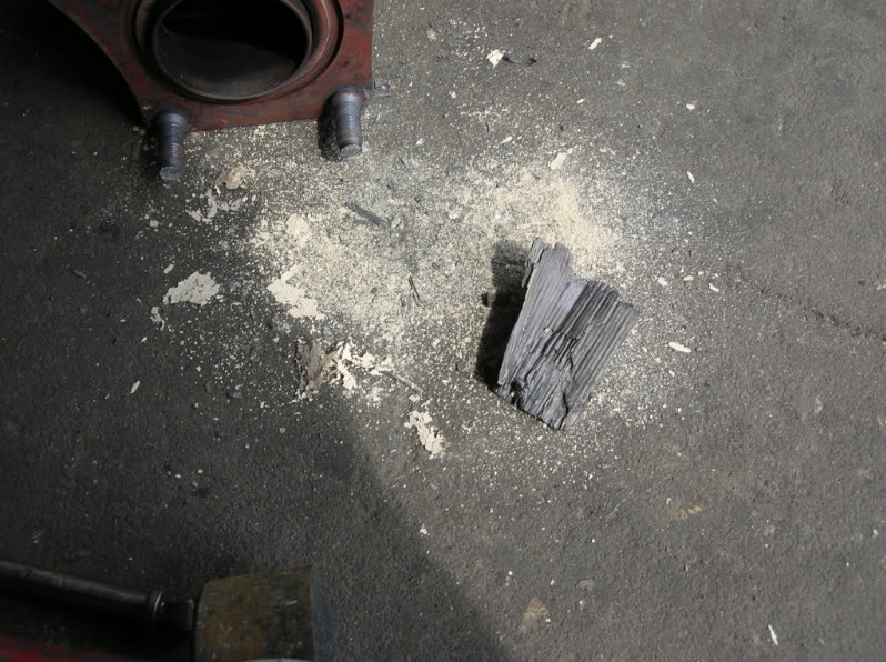
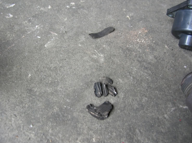
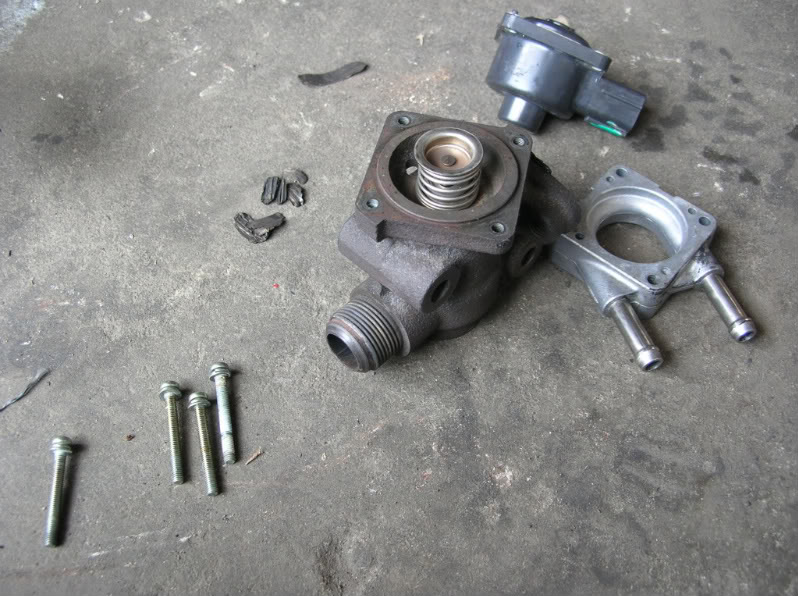
This is why I had to purchase a set of Cattman Headers. The precat facing the front grille wasn’t so bad but definitely needed to be changed. Now, the precat facing the firewall was absolutely terrible. So terrible that the catalytic material completely jammed up my EGR valve pretty bad. Anyone that gets the SES light> P1402 code try your hardest not to ignore it. Below are some pics of the EGR valve taken apart and cleaned. Along with some of the bad catalytic cone material break-up.
This is all the crap that came out the Egr valve alone.
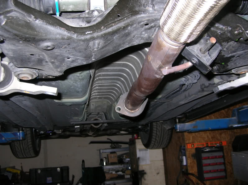
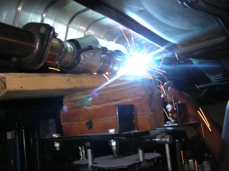
I had my mechanic weld a High Flow Cat on that I purchased from Advance Auto Parts. I’m just waiting to weld on the o2 sensor bung and extend that last o2 sensor wire. Instead welding the High Flow Cat onto the Racingline Y-Pipe. We just welded it on 6 to 7 inches further back.
Welding on the High Flow Cat
Additional Photos from DeusExMaxima
Original Pricing Below (This is for reference purpose only. Pricing is from 2010):
Headers only, AT or MT version, no EGR port (07/08 Maximas) – $599.99 retail, $569.99 w/ org discount
Headers only, AT or MT version, with EGR port (04-06 Maximas, 05/06 Altimas) – $629.99 retail, $598.49 w/ org discount
Y-pipe only, AT or MT version, NO cat and NO “extra” O2 ports – $379.99 retail, $360.99 w/ org discount
Y-pipe only, AT or MT version, WITH high-flow all-metal cat and NO “extra” O2 ports – $579.99 retail, $550.99 w/ org discount
Y-pipe only, AT or MT version, WITH high-flow all-metal cat AND two O2 ports behind the cat – $599.99 retail, $569.99 w/ org discount
Header/Y-pipe system, AT or MT version, NO cat or “extra” O2 sensors – $939.99 retail, $892.99 w/ org discount; add $29.99 for EGR port
Header/Y-pipe system, AT or MT version, WITH high-flow all-metal cat and NO “extra” O2 ports – $1139.99 retail, $1082.99 w/ org discount; add $29.99 for EGR port
Header/Y-pipe system, AT or MT version, WITH high-flow all-metal cat and TWO O2 ports behind the cat – $1159.99 retail, $1101.99 w/ org discount; add $29.99 for EGR port
Note from Cattman:
Because installation of the headers requires removing the precats, its necessary to make the secondary O2 sensors happy (because they monitor pre-cat function) to avoid related error codes. In a 2004 Maxima, this can be done with an O2 simulator or by installing a main cat in the y-pipe, followed by two O2 ports for the secondary sensors. This is not confirmed, but it “appears” that an O2 simulator will not fool the ECU in 2005 and later Maximas and Altimas, so installing a cat and two O2 ports in the Y-pipe may be necessary to avoid a CEL.
I broke yet another wheel stud and instead of paying the dealership $70 to do it, I decided to do it myself this time. I spent $4.04 (for replacement stud) + $1.00 (for 6 washers). This sure beats paying somebody else to do the work and is definitely more gratifying.
Hopefully, this DIY helps you guys who need their wheel stud(s) replaced.
Level of difficulty:
1.5 out of 5 (5 being hardest)
Approximate install time:
45-90 minutes
Tools:
floor jack and jack stands
socket wrench/ratchet
14mm (9/16″) and 19mm (3/4″) sockets
wd-40 or pb blaster or liquid wrench
~6 washers
hammer or mallet
Replacing the wheel stud:
*I did the rear left side. The fronts should involve the same steps, but may or may not require different socket sizes.
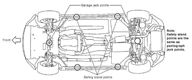
1: Jack up the car high enough using the standard jack points (or frame) so you can slide under the car easily.
2: Remove the wheel, exposing the studs, rotor, brake components, etc.
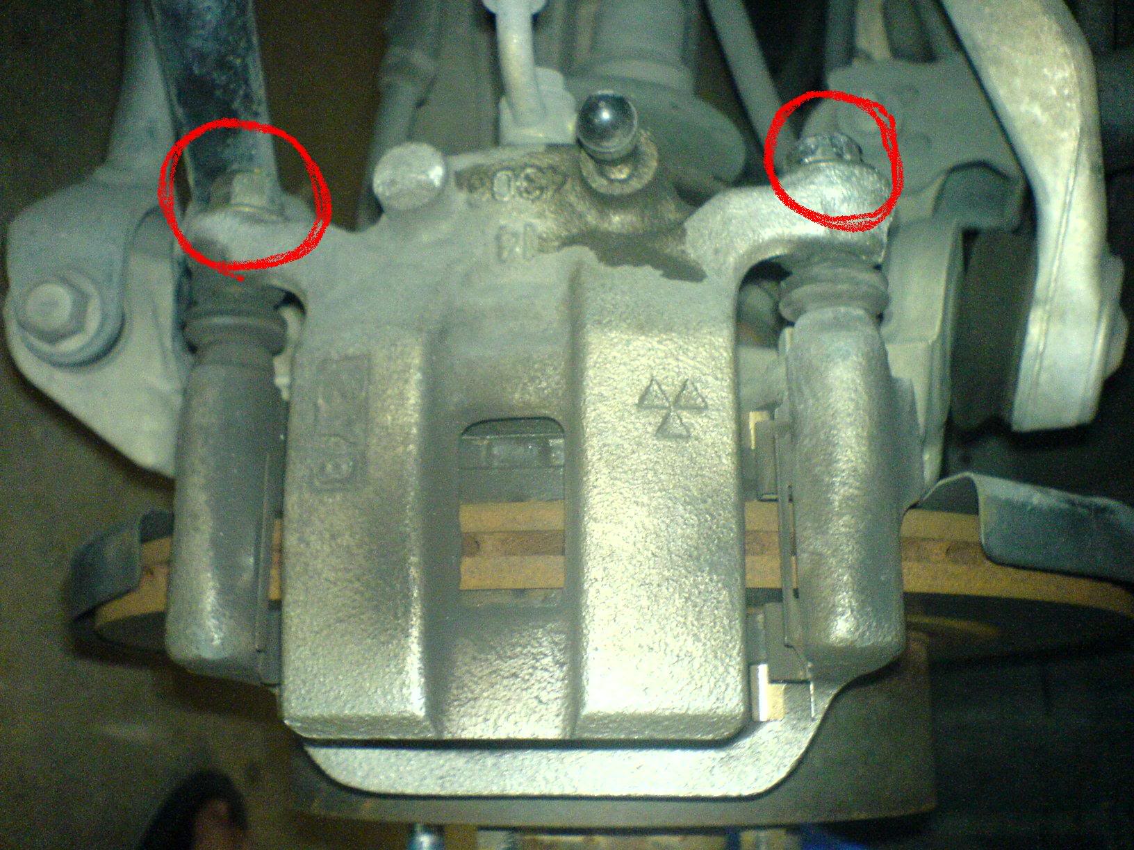
3: Locate the two 14mm bolts holding the brake caliper in place and remove them.
*Spraying the bolts with wd-40/pb blaster/liquid wrench makes the job much easier, especially if these bolts have not been removed recently.
**The bottom bolt cannot be taken off due to limited space behind it, so I used my floor jack to push up the suspension to create more space.
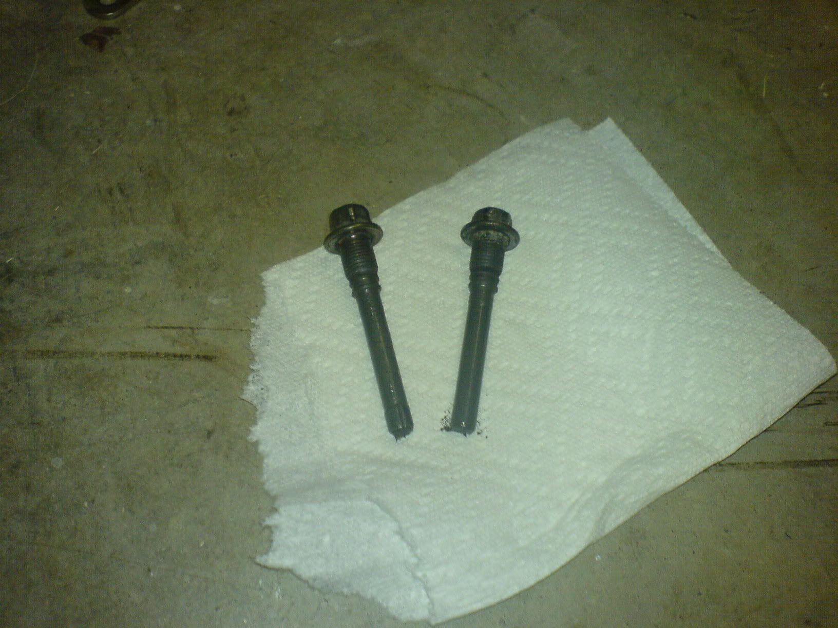
4: Put the bolts some place where the grease won’t collect stuff off the ground.
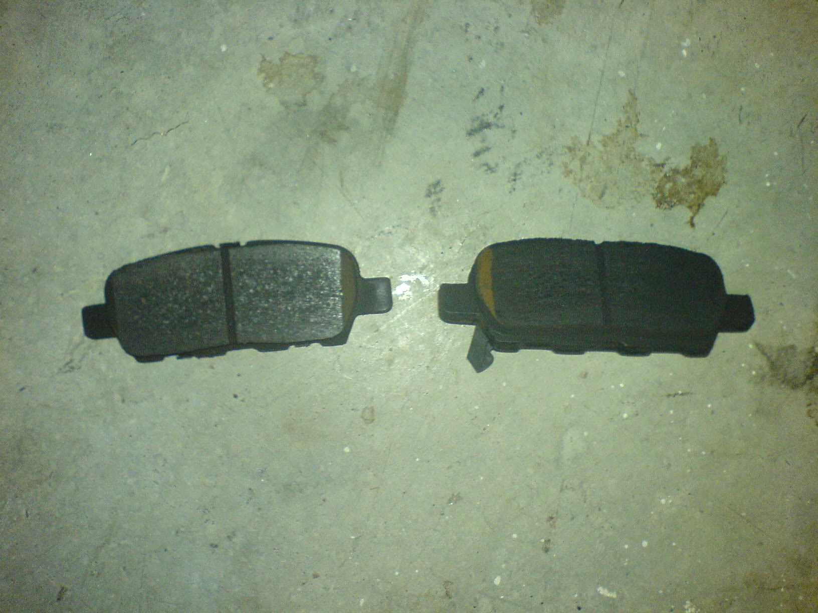
5: Rest the brake calipers so that it does not put any strain (put weight on) the brake lines. Take off the brake pads, if you haven’t already.
6: Locate the two 19mm bolts holding the brake caliper bracket in place and remove them.
*Spraying the bolts with wd-40/pb blaster/liquid wrench makes the job much easier, especially if these bolts have not been removed recently.
**I couldn’t take off the bolts by hand so I used the floor jack (while making sure the socket is on the bolt completely as to not strip it).
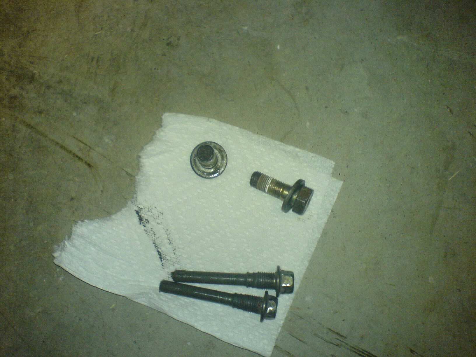
7: Put the bolts some place where you won’t lose them.
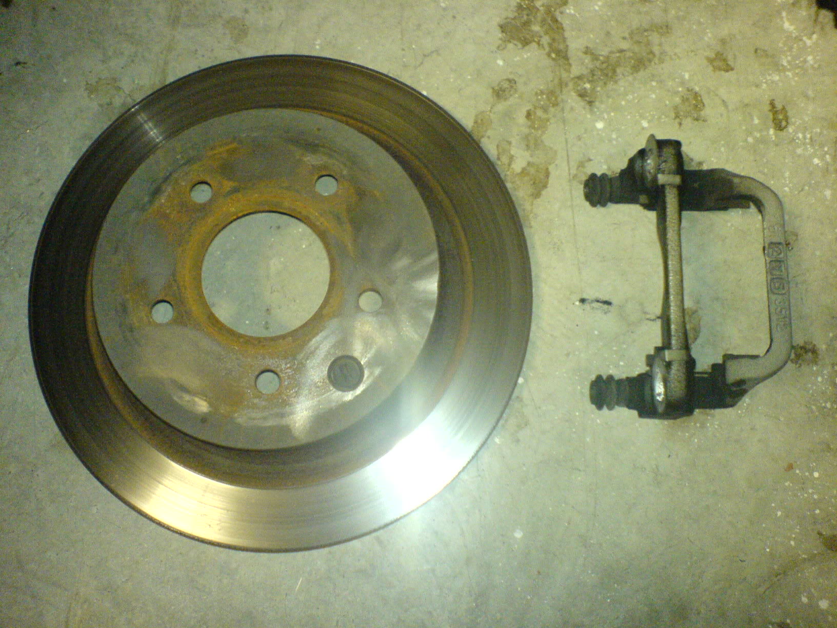
8: Remove the brake caliper bracket and the rotor and set it aside. They should just slide right out.
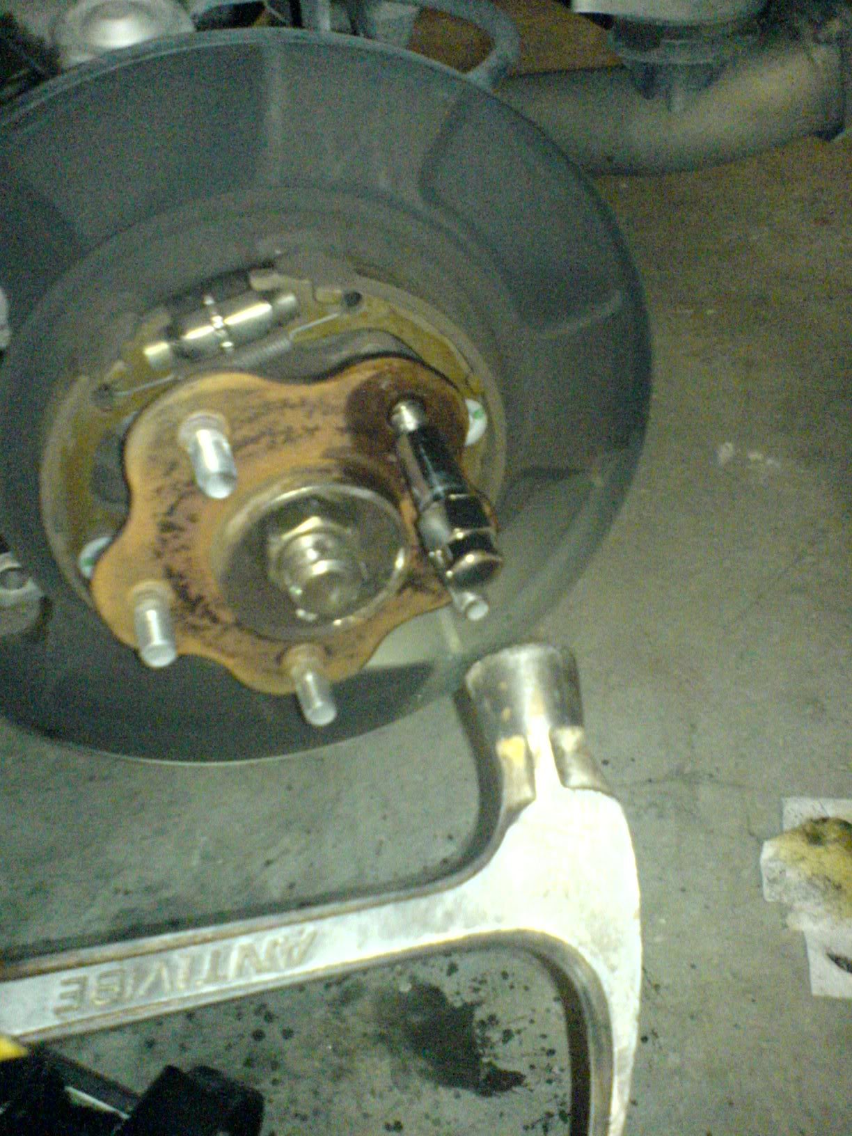
9: Spray wd-40/pb blaster/liquid wrench where the broken stud is and around it. Hammer away at the broken stud. (Optional: thread in an old/useless lug nut a little bit for added length and to prevent the stud from flying somewhere)
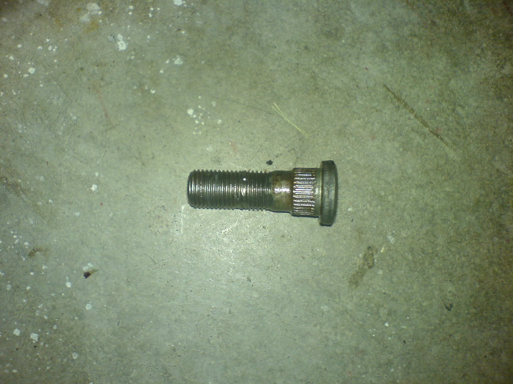
10: Take out the broken stud.
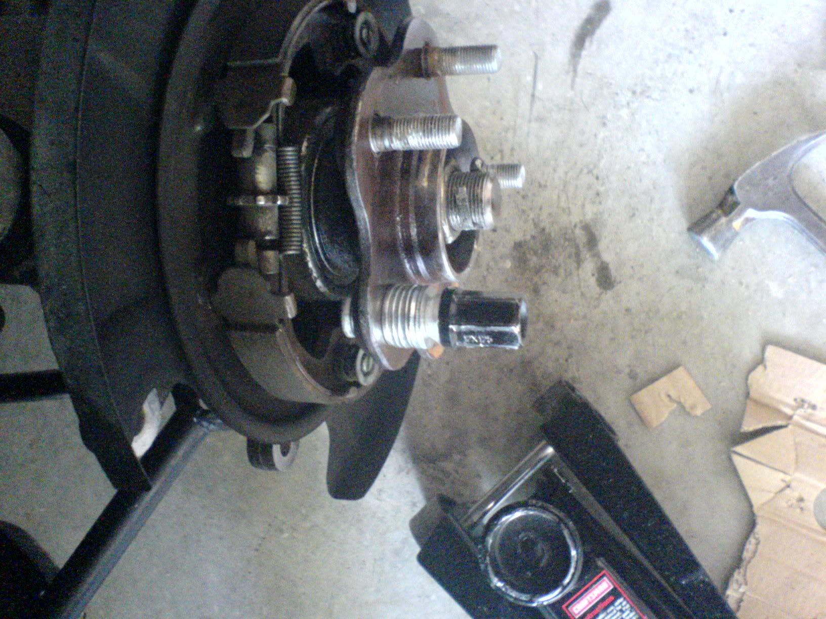
11: Spray the new stud down with wd-40/pb blaster/liquid wrench and put it through the hole where the broken stud was. Place ~6 washers on the stud and tighten the lug nut. Stop tightening when you can feel the head of the stud become flat like the other studs.
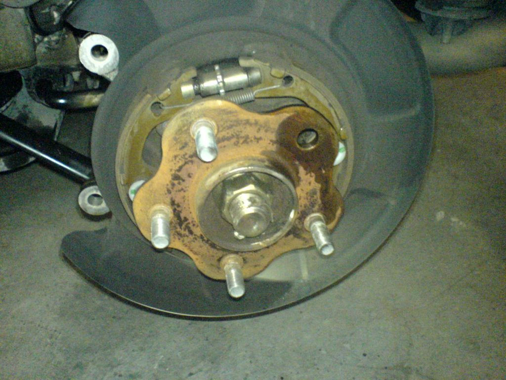
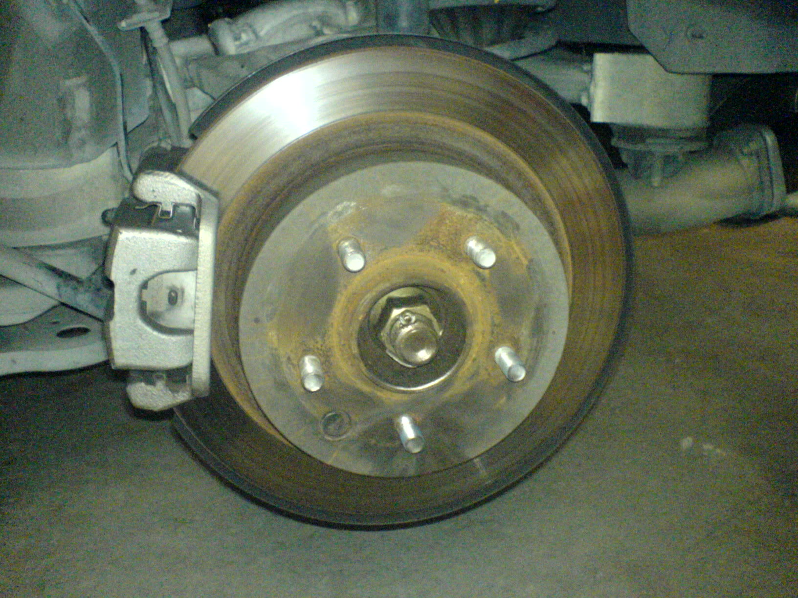
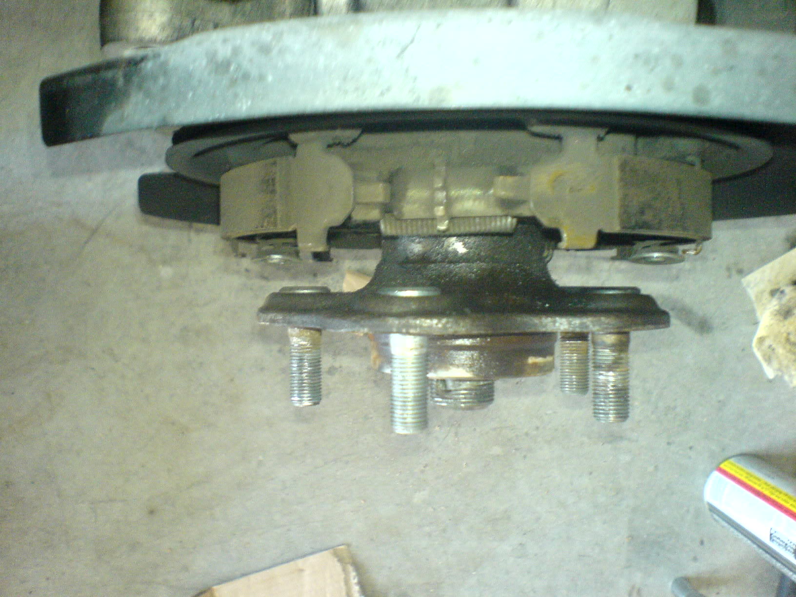
12: You’re done! It should look like this.
13: Now put everything back together in the opposite order that you took them out in.
[self explanatory]
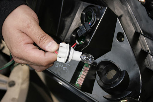
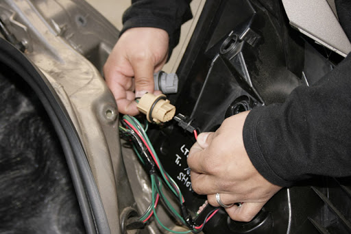
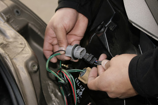
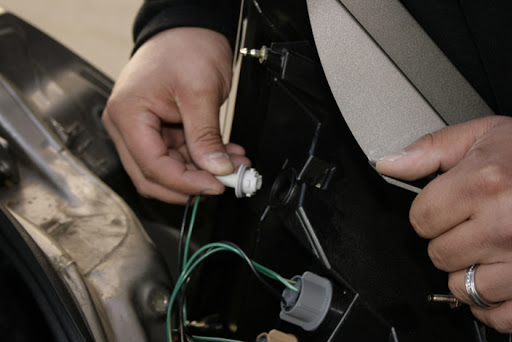
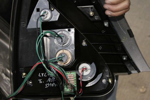
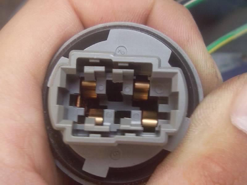
Basically what is going on is that the connector on the oem bulb is thicker that the connector the led tail lights, so all you have to do (make sure the car is off and you don’t have the any lights on) is close the pins on the stock connector and spread apart the pins on the lights, look at the pics.
And once again, make sure you have the black cable line up with the white black cable on the car!!!
BEFORE
AFTER (MAKE SURE THE LEADS DON’T STAY TOUCHING EACH OTHER AFTER YOU OPEN THEM)
This should work on all Cali spec Maximas. When dealing with codes P0420 and P0430, whether its voluntary removal of or just bad pre-cats, the O2 sim helps keep your SES/CEL/MIL light off and typically also prevents the ECU from storing any related codes. Rear 02 sensors only monitor if the cats work and do not affect the long or short trim fuel so basically, they do not affect drivability or the air/fuel ratio. Since the ECU is monitoring catalyst efficiency using the rear O2 sensors and the O2 sim simulates the proper voltage for the ECU to think that the cats are working. For more info, see www.o2sim.com.
Btw, I was throwing a CEL for P0037 and P0057 (I did the self diagnose procedure and counted the SES/CEL blinks) codes before, since my secondaries were completely unplugged and off the car. After installing the dual output sim and reseting the ECU (the procedure was a pain in my arse), the CEL is gone. I still have to drive it around some to make sure it stays off, so we’ll see how that works out.
And yes, my secondary O2s are just ziptied under my engine cover.
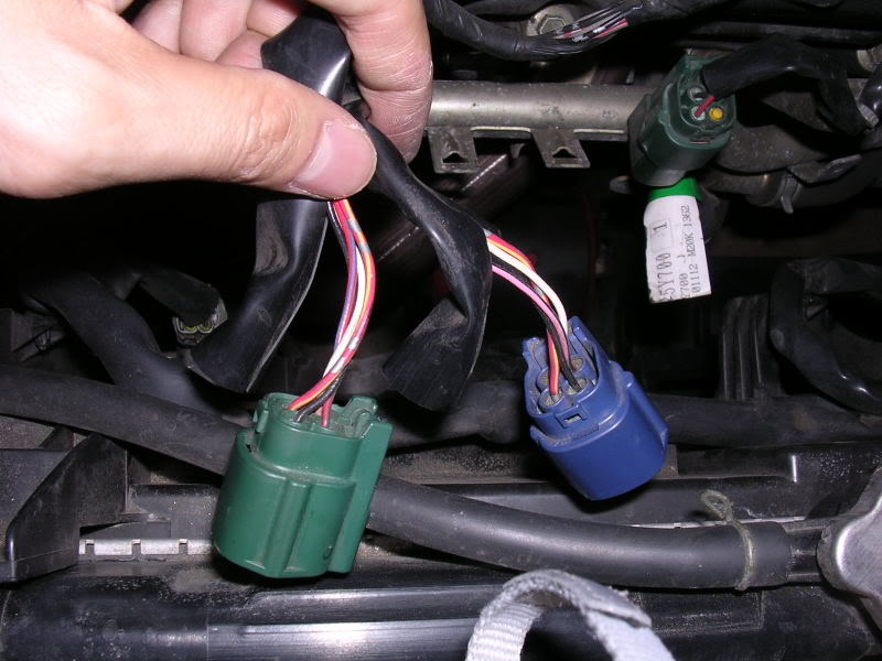
The wires tapped into are the wires BEFORE the connectors for the rear/downstream/secondary O2 sensors (so the length of wiring going from the ECM to the connectors). The dark blue connector connects to the WHITE wire shroud/harness and this is for the Bank 1 (rear bank) downstream O2 sensor. The green connector connects to the RED wire shroud/harness and is for the Bank 2 (front bank) downstream O2 sensor. Cut back the black wrap before each connector and you should see 4 wires:
Black: Ground
White: Signal
Red/Yellow: Power
Red/Blue: Heater
If you are going to simulate BOTH secondary O2 sensors, be sure to have bought a dual output sim with one black wire (ground), one red wire (power), and two white wires (signal).
The installation for a single output sim is the same, except you just tap into the signal of the sensor you want to simulate instead of both.
On ONE O2 sensor harness:
Using a wire stripper, strip about half an inch to expose the copper wires under the ground and power wires.
Tap the black wire from the O2 sim to the black (ground) wire.
Tap the red wire from the O2 sim to the red/yellow (power) wire.
Cut the white signal wire and connect one of the white wires from the O2 sim to the end that is going back to the ECU.
On the other O2 sensor harness:
Cut the white signal wire and connect the second white wire from the O2 sim to the end that is going back to the ECU.
Heater wires:
Leave em intact and both secondaries plugged into their respective connectors, the ECU still needs to read these or it will throw a code for heater malfunction or something.
You can now either solder the joints and wrap them up in heatshrink or electrical tape, or you can clear the codes and start the car to see if the sim is doing its job before soldering. The yellow LED on the sim should be blinking when the car is on/running.





















 AFTER (MAKE SURE THE LEADS DON’T STAY TOUCHING EACH OTHER AFTER YOU OPEN THEM)