Category

my5thgen 00-03

Category

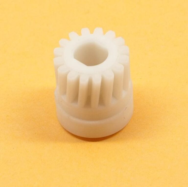
Are you tired of going to the dealer for repairs when you know you can do it yourself? Got a broken power seat that is just driving you nuts? This seat gear for the front driver and passenger seats on all Nissan and Infiniti model 2003-2010. Fix that broken power seat and regain your memory positions as this is a quick fix back to a comfy position.

Check out the tutorial that we have provided and see how you can make this a fix and not go to the dealer. Dealers are asking upwards of $1400 for a new seat because they say it’s not possible to fix. Please verify your seat gear before purchase for easier processing. A simple look at the gear will help determine proper choosing.

Installation Instructions: Infiniti_Nissan_FAQ_Seat_Gear_Replacement

#1 is driver’s side with neck and collar
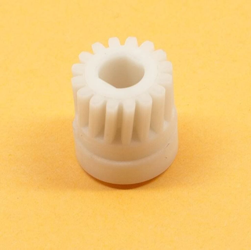
#2 is driver’s side without neck and collar with spline shaft
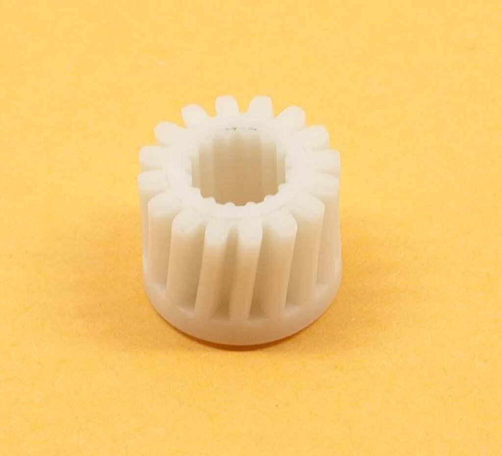
#3 is the passenger’s side without neck and collar with a smooth shaft
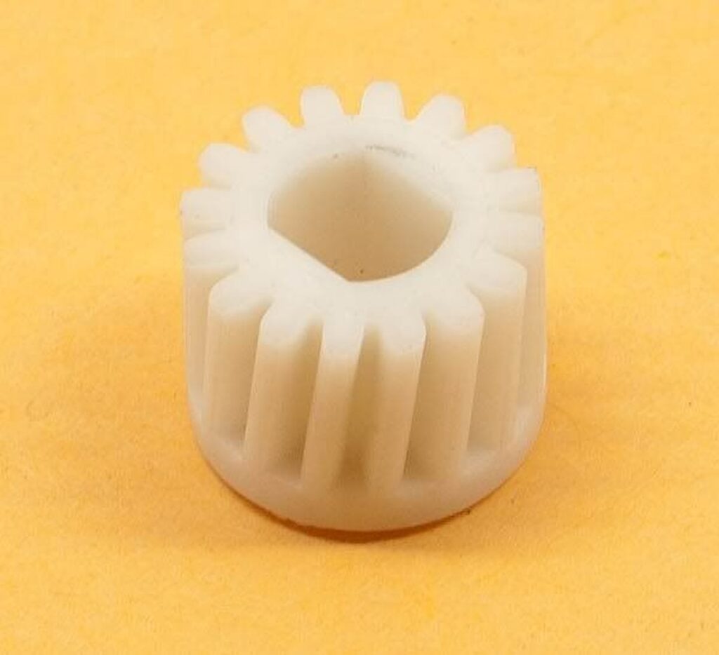
Via Odometer Gears

Order Link: https://www.odometergears.com/products/Infiniti/Seat+Gears+%28ALL%29+01-Present/98
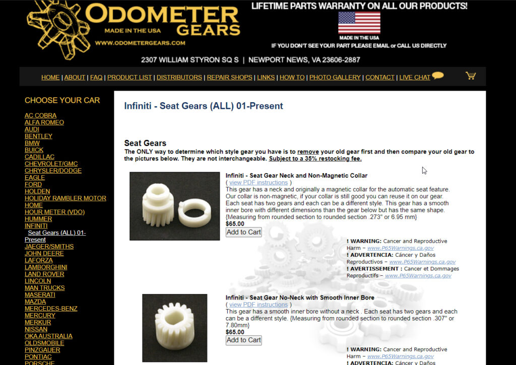
The ONLY way to determine which style of gear you have is to remove your old gear first and then compare your old gear to the pictures below. They are not interchangeable. Subject to a 35% restocking fee.

Infiniti – Seat Gear Neck and Non-Magnetic Collar ($65.00)
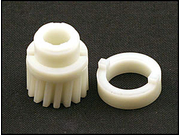
Infiniti - Seat Gear Neck and Non-Magnetic Collar

This gear has a neck and originally a magnetic collar for the automatic seat feature. Our collar is non-magnetic, if your collar is still good you can reuse it on our gear. Each seat has two gears and each can be a different style. This gear has a smooth inner bore with different dimensions than the gear below but has the same shape. {Measuring from rounded section to rounded section .273″ or 6.95 mm}.

Infiniti – Seat Gear No-Neck with Smooth Inner Bore ($65.00)

Infiniti - Seat Gear Neck and Non-Magnetic Collar

This gear has a smooth inner bore without a neck. Each seat has two gears and each can be a different style. {Measuring from rounded section to rounded section .307″ or 7.80mm}

Infiniti – Seat Gear No-Neck with Splined Inner Bore ($65.00)
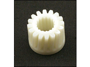
Infiniti - Seat Gear No-Neck with Splined Inner Bore

This gear has a splined inner bore without a neck. Each seat has two gears and each can be a different style. {This is the only splined style gear and does not require to be measured.}

Loading

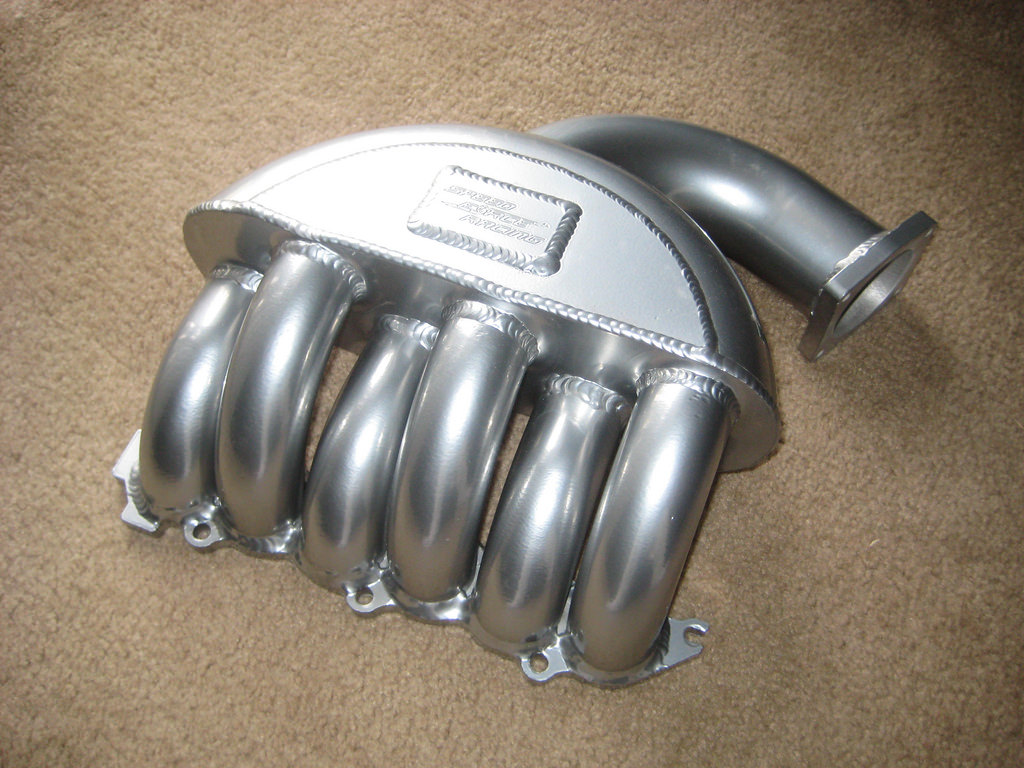
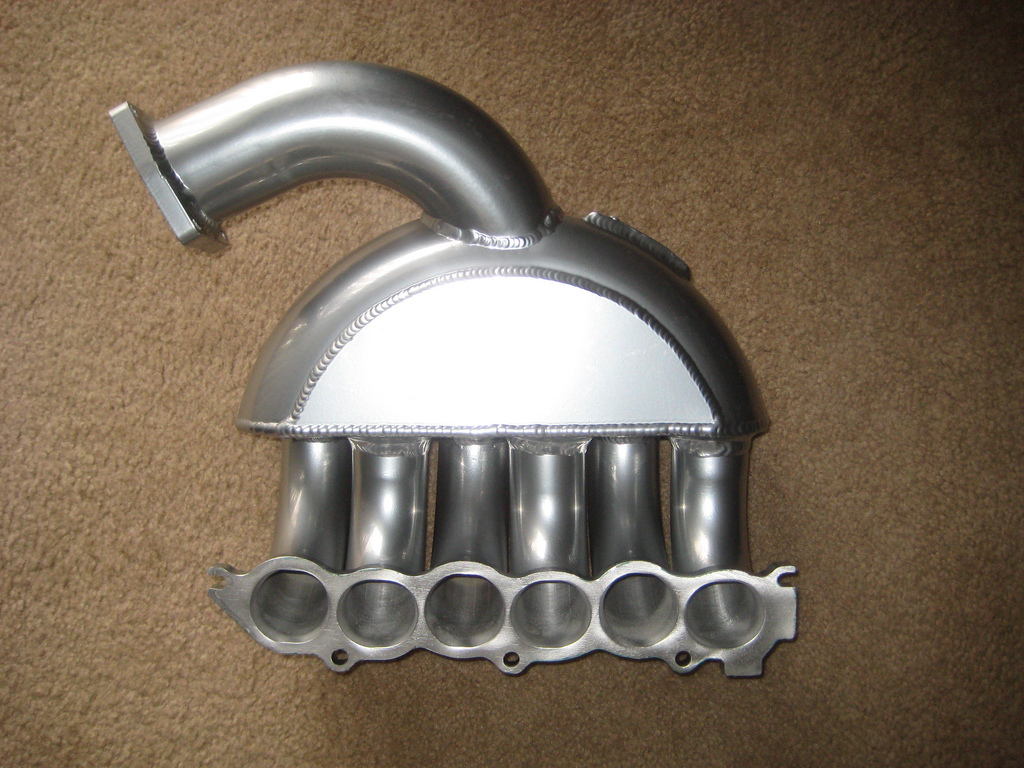
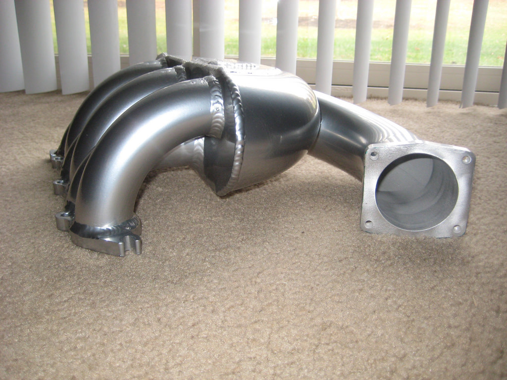
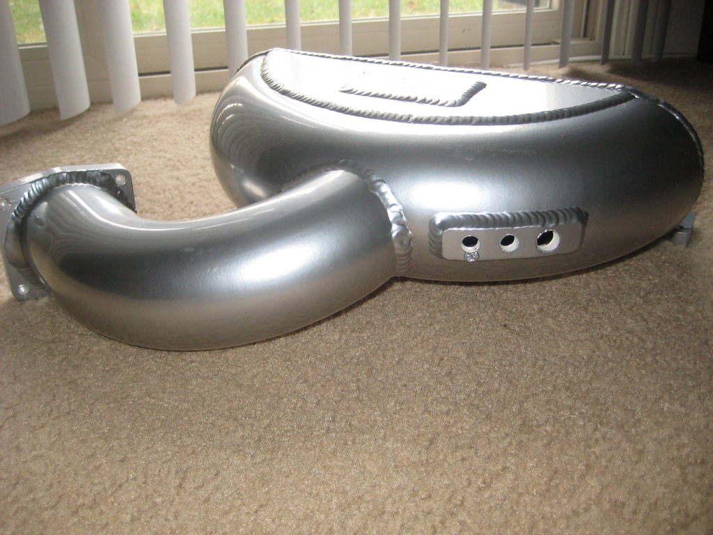
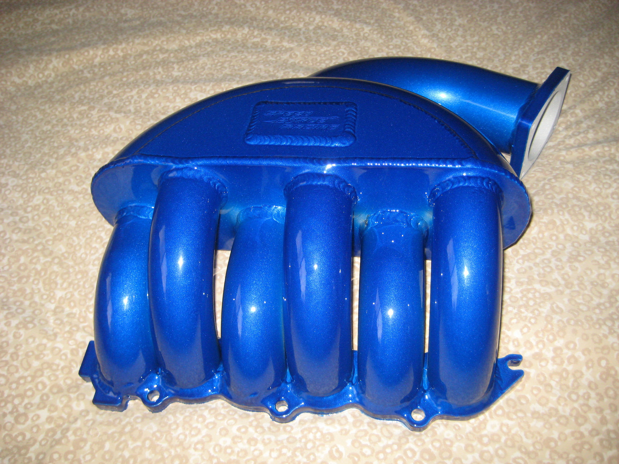
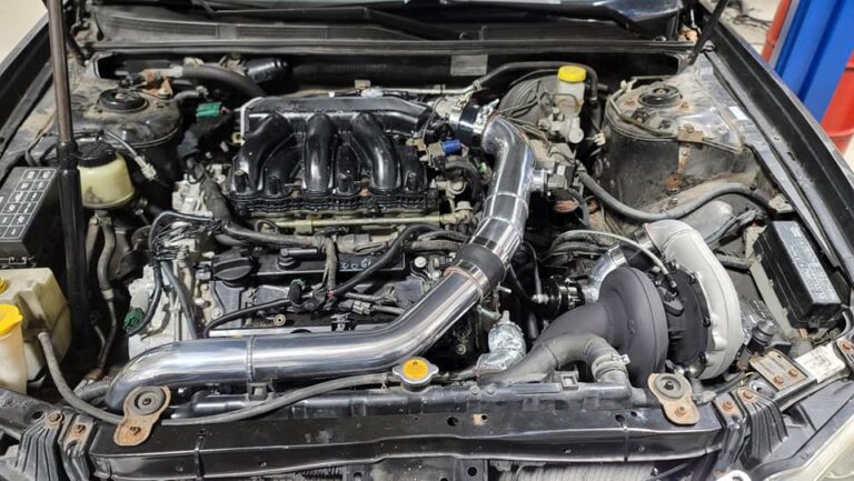
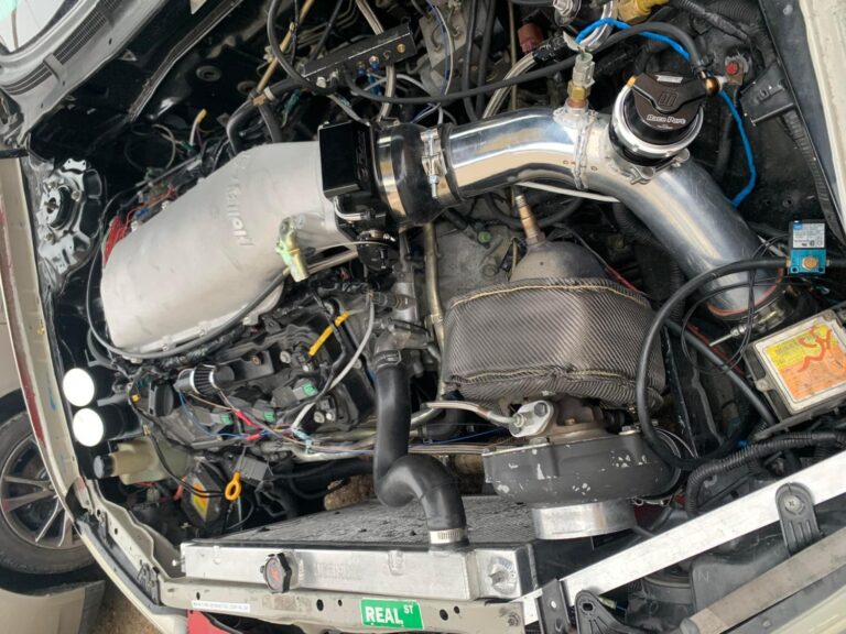
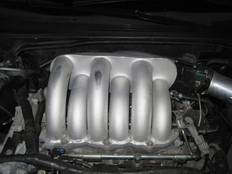
If you want to add an easy 25WHP to your Altima or Maxima then look no further. Our SFR high-velocity manifold is an easy bolt-on and adds 25WHP to an NA car and up to 50WHP on turbo cars. We also offer an aluminum engine cover that goes with it to really dress up the engine We also offer the intake manifold for the later models Altimas and Maximas.

Nissan Club

I was fortunate enough to have the first SFR High-Velocity Manifold put on a N/A vq35. From what Tim at Speed Force Racing told me this manifold is slightly different from the manifold made for forced induction cars.

I have had the manifold for months. When I first received it I was impressed with what I saw. The design is wicked and looks waaaayyy better than stock. It took me a while to slap it on at first because I had to find and purchase the correct barb fitting to hook up the vacuum hoses. At first, the installation was a bit time-consuming because I didn’t know what I was doing. I have installed the manifold on and off about 6 times already so installation for me is under an hour.

The sound is pretty cool. At low revs during soft acceleration, you hear a humming/growl from under the hood. Under hard acceleration, the engine sounds great! it isn’t loud and obnoxious. It’s more of a deeper growl, nothing too crazy or far from stock, but noticeable.

At first, I could only go off of the butt dyno and my butt dyno liked what I felt. To me, the mid-range was increased a lot. I knew the torque was increased a lot (dyno showed 10wtq at peak). Up top, the car felt great as well. My car just easily pulled to higher RPMs. I could definitely feel the car breathing MUCH better. Even while cruising at lower RPMs the car had sooo much better response.

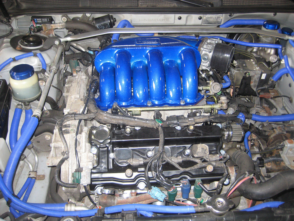
Here are some pics of what it looks like on my car:

Some graphs got mixed up at the shop but I managed to get the most important ones. The graph shows the highest dyno from the stock manifold with the highest dyno with the SFR manifold. the other graph has the highest stock vs. a couple runs with the SFR manifold but also shows the torques as well.

I picked up almost 30whp at redline alone.

I was amazed at how much power was picked up at redline. this isn’t your average SSIM dyno graph only showing gains up top. You can clearly see there are gains on the ENTIRE powerband. Peak rose 5whp (wish it was more). What’s important here is the area under the curve. midrange you can see ~12whp gains as well!

I like this manifold very much! yes, it’s not a cheap mod but for the overall power, it’s worth it. It adds power where cams don’t and cost half the price. Plus install isn’t that hard. To me, it was well worth the money spent.

Additional Reference Photos

Loading

Community Member Credit: CMax03

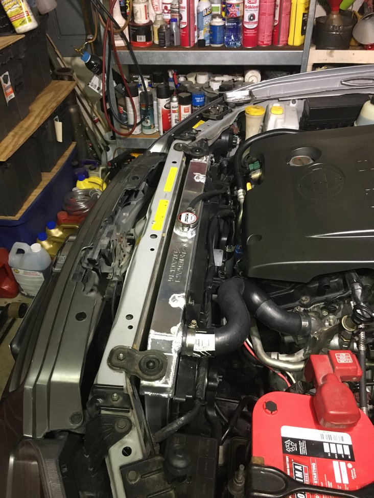
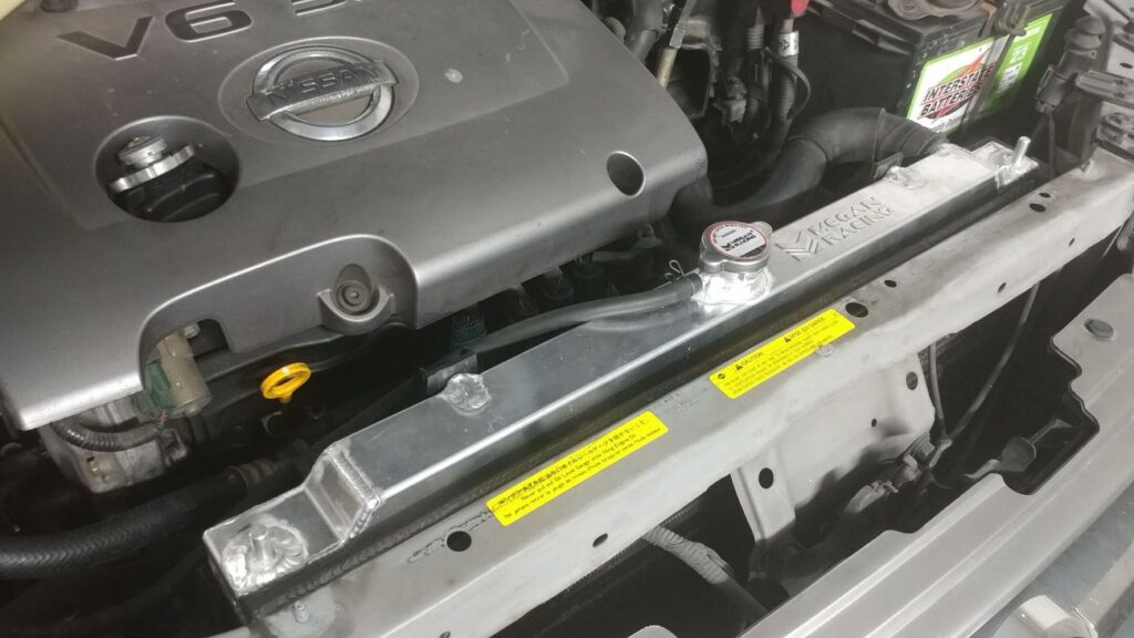
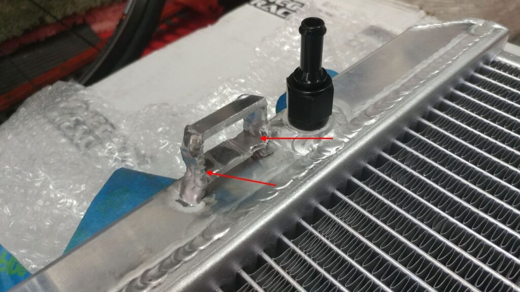
I’ve installed the Megan Racing Radiator and I love it! It’s 1-7/16” thick core versus the OEM 1” thick core. No drain! So what, it has a lower radiator hose. Everything fit the only minor issue is the upper support pegs are slightly lower than OEM & the filler cap is slightly to the right causing the overflow hose to have a little less slack. That’s it fan shroud is closer to my Cattman Headers but they’re ceramic coated so and they don’t really radiate that much heat so applying some of that thermal barrier tape might be a good idea. Function tested it and it works great!

Side by side view with OEM radiator.

Reference Info by SquidBeak

Thanks for the follow up wellshii19.

CMax03, perfect timing! Thanks for the info and the pics. Looks great!

I know it’s overkill, but I really wanted a drain plug. So I bought a bung, drilled the bottom of the radiator then had a local guy weld it in. Then I got an aluminum elbow, plug and a pvc valve for draining. Now, it’s pretty slick. I’m going to do the install this week.

I did a test to see how everything would work this afternoon and I think it’s going to be nice. I was surprised to see that the Megan radiator only holds 1 gallon. I thought it would hold more. I think the original radiator only holds about a gallon also, but I’m not positive about that.

I just finished installing the radiator. Overall, I’m pretty happy with it.

Here are some observations I made in the process:

1. I wasn’t very impressed with the AN6-5/16 barb fittings that came with the radiator. They looked like leaks waiting to happen so I used some nicer aluminum fittings. Add 5-10 HP minimum per fitting.

2. I had to file down the welds on one of the fan brackets to allow the fan shroud to fit. Not a big deal. Add 1-2 ponies due to weight savings.

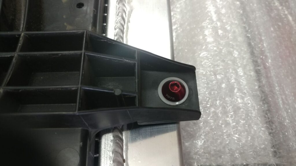
3. The 2 screws that hold the fan shroud on the original radiator thread into plastic and are basically sheet metal screws. You can’t reuse these screws, you will have to get some M6 x 1.0 screws for the new radiator. These cool red screws easily freed up 15 ponies each.

4. The drain plug made the 7-8 drain & fills much easier. Really too bad they didn’t include one. The plug was good for at least 15-20 ponies.

5. This is the most important. The original radiator cap is rated at .9 bar (13 psi). The Megan cap is 1.1 bar (16 psi). With the Megan cap there was no exchange between the radiator and the reservoir at all. None, no fluid nor air. I decided to re-use the original cap and this restored the function of the reservoir. -10 ponies for reusing old cap.

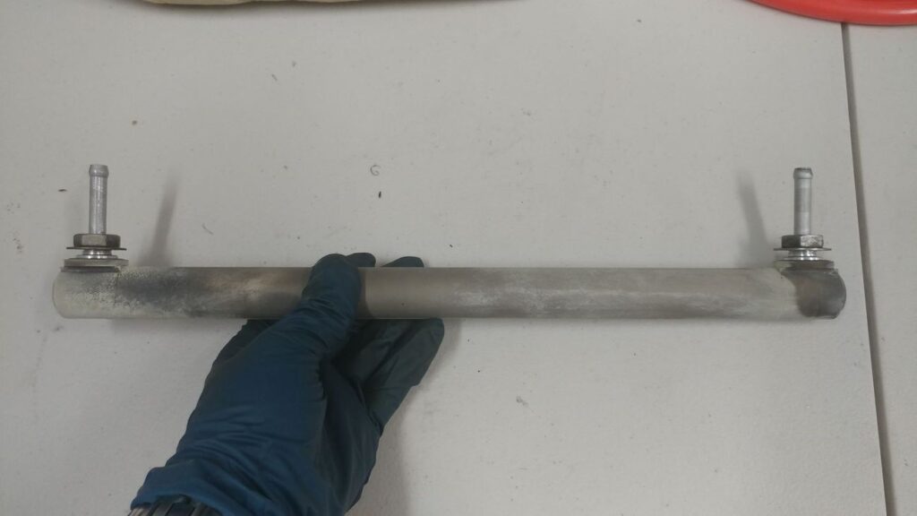
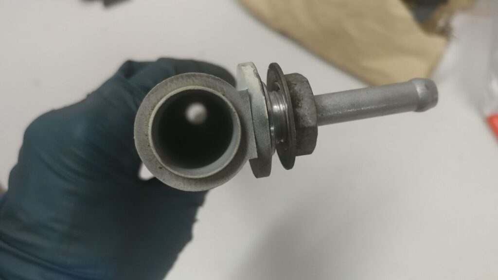
6. I decided to dissect the old radiator mainly because I was curious to see how the trans cooler works. I thought it would be just an aluminum pipe immersed in engine coolant. However, it’s actually a pretty ingenious design. It’s a hollow cylinder that the ATF flows through. This allows coolant to cool the inside and outside of the cylinder. I looked inside the Megan radiator with a scope and it has the same design.

Original ATF cooler.

ATF Cooler side view.

Megan ATF cooler

7. I did the intake manifold coolant bypass while I had the old radiator out. When I pulled one of the hoses off, some black liquid came out. This is strange because all of the coolant looked immaculate when I flushed it. No idea how this could happen. Any ideas? I blew out the coolant lines in the manifold with compressed air then looped one of the spare hoses to the other port of the manifold to plug them both.

8. During a 30 mile test drive, I noticed that the coolant temps now range between 190 and 208. Previously, it was 195-205. It probably doesn’t mean much, but it’s interesting.

9. Easily 50-60 HP gained on the butt dyno. Easily. Probably way more. WAY MORE. Definitely.

Loading

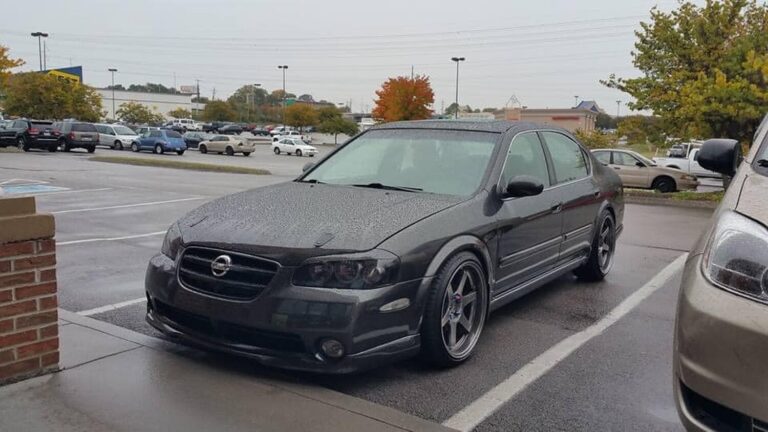
Owner: Jared Floyd

Year: 2002
Model: Maxima
Current Color: Silver
Transmission:  6-Speed Manual
Trim: SE

Mod List:

  • NWP Block-off Plate
  • NWP 5pc Thermal Spacers
  • NWP 75MM Throttle Body
  • NWP Torque Brace
  • Strut Tower Brace
  • 3.5 Admintuned Intake
  • Reflashed ECU
  • Stillen Oil Cooler
  • Gutted Upper Intake Manifold
  • Long Tube Headers + Unequal Y-Pipe
  • 3″ Exhaust
  • Mishimoto Aluminum Radiator + Thermostat
  • AEM AFR Gauge
  • Battery Relocated to Trunk
  • 6thgen Maxima Rotors (Bigger Brakes)
  • Fully Built 4:1 Final Drive Spec V Gears (Redline MT-85 Gear Oil)
  • Fidanza Lightweight Flywheel
  • Southbend Stage 2 Clutch (No Slip)
  • Stillen Front Lip
  • BC Coilovers
  • Clear Tailights/Custom Headlights
  • Double Din Radio
  • 350z Wheels
  • 2 10″ Subs

Loading

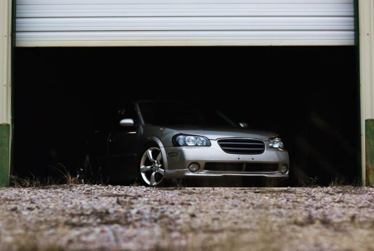
Owner: Cameron Rice

Year: 2002
Model: Maxima
Current Color: Silver
Transmission:  6-Speed Manual
Trim: SE

Mod List:

Engine

  • NWP Block-off Plate
  • NWP 5pc Thermal Spacers
  • NWP 75MM Throttle Body
  • NWP Torque Brace
  • Strut Tower Brace
  • 3.5 Admintuned Intake
  • Reflashed ECU
  • Stillen Oil Cooler
  • Gutted Upper Intake Manifold
  • Long Tube Headers + Unequal Y-Pipe
  • 3″ Exhaust
  • Mishimoto Aluminum Radiator + Thermostat
  • AEM AFR Gauge
  • Battery Relocated to Trunk
  • 6thgen Maxima Rotors (Bigger Brakes)

Transmission

  • Fully Built 4:1 Final Drive Spec V Gears (Redline MT-85 Gear Oil)
  • Fidanza Lightweight Flywheel
  • Southbend Stage 2 Clutch (No Slip)

Exterior

  • Stillen Front Lip
  • Varstoen ESH 18×11 Stretched Tires
  • BC Coilovers
  • Clear Tailights/Custom Headlights
  • Double Din Radio
  • 2 10″ Subs

Loading

Community Member Credit: asand1 / maxima_se007

Important Note: This should really be used as a temporary solution. The proper fix is to replace either the knock sensor itself or the harness which is known to go bad. Most people do both at the same time.

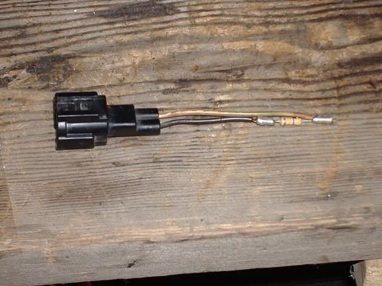
Resistor: 470K

Order Link: https://www.radioshack.com/products/radioshack-470k-ohm-1-2w-5-carbon-film-resistor-pk-5?variant=20332249541


Instructions

  1. Disconnect the knock sensor at the easily accessible connector. (you can find this by looking at the knock sensor and following the wire and wire loom towards the engine bay.)
  2. Buy a package of 5 one megohm resistors at radio shack for $0.99. (Part #: 271-1134)
  3. Take 2 of the resistors out and put them next to each other (side by side) and twist one wire on each resistor onto the one next to it from the other resistor. You now have a 500k resistor. (you can buy a 470k resistor, but i felt this would give truer results to knock sensor specs seeing as how a good knock sensor is between 500k-600k ohms.) DO NOT twist only one side, creating a 2000k ohm resistor (by going —(***)-x-(***)— (imagine the —(***)— is a resistor and x is a twist) that is the wrong way, just imagine you have to make one resistor unit out of two. If this is confusing, just get a 470k resistor.
  4. Insert one twisted wire (single wire if using 470k) into one receptacle of the connector in the engine bay (not the one leading to knock sensor) and the other twisted wire (single if using 470k) into the other receptacle on the same connector. You are eliminating ANY use of the knock sensor or the wire connected to it.
  5. Use electrical tape to keep it secure and to avoid any short-circuiting.
  6.  Enjoy some extra power (if your knock sensor was bad), but look out for knocking which can be potentially harmful to the engine if excessive.
  7.  I would recommend you check your codes before doing this to find out if your ks is in fact bad. I would also use this as only a TEMPORARY solution until a new ks is purchased and installed. Use the highest octane you can get too, because it will help in the prevention of knocking.

Installation Photos

Stock Sub-Harness

Notice the KS Sensor attached at the right. You will want to use the end at the left. Strip off the electrical tape and wire loom. Then strip the tape from all the connections. Clip the black wire where it is crimped to the shielding. Pull the shielding from the clear wire. Strip the black wire about 1/4″. I used a 16Ga butt connector cut in half, and solder to connect to the 470k resistor. Now clip the other end of the resistor and the clear wire even. Strip about 1/4″ from clear wire and solder using the other half of the 16Ga butt connector.

It should look like this now.

Now use shrink tubing to protect. I folded the end over and added another short piece of tubing.

Now put the sub-harness connector back on its bracket and plug the engine harness plug back in.
Loading

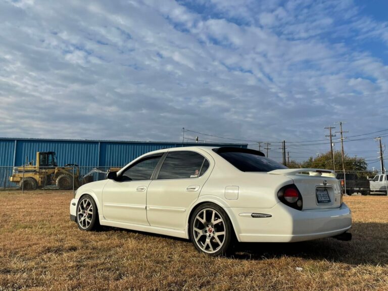
Owner: Jose Gutierrez‎

Year: 2000
Model: Maxima
Color: Red
Engine: Gen2 VQ35DE (Full Swap)
Transmission: 6-Speed Manual (Originally 5-Speed Manual)

Highlights:


Videos:

Loading