Category

my4thgen 95-99

Category

Community Member Credit: The Wizard

1. ECU pinout for 99 is much different than 95-98’s. Regarding installation of the EU, pin 44 needs to be changed to pin 46.

2. Jumper Pin 13 must be set to OPEN (not 1-2 as shown on page 27 of Dan’s writeup), otherwise your fans will not kick on and your car will overheat. I’ve tested this. Thanks for the footnote Dan!!

3. The 99 FSM is all screwed up, so don’t go by it. Hours and hours were wasted trying to figure out the 99 FSM and compare it to the other year FSM’s I have. The 99 FSM led me to believe that 3 pinouts had to be changed at first. Before I hacked or cut a single wire, I did a continuity test (per Dan’s recommendation) and figured out which wires were really what. Only one wire on Dandy’s ECU diagram had to be switched as stated above.

4. My Emanage Ultimate is version D. I don’t have any CEL’s!!
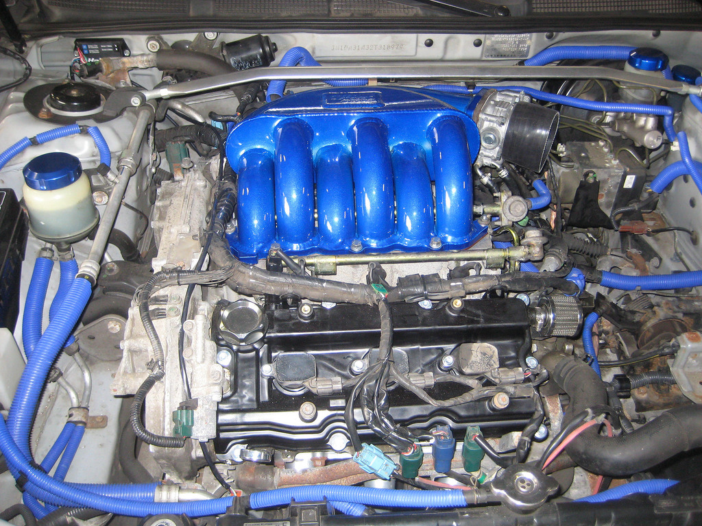
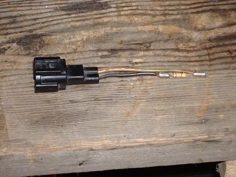
This illustrates that resistors don’t need to be soldered in (for version D).

5. Also, I have no issues with burning/melting coilpacks as some have experienced.

Last but not least, I would like to give a big thank you to Dan (Dandymax). I sent him 3 or 4 emails asking for help/clarification on several issues before the install. Dan always got back to me within 24 hours or so and provided in-depth explanations. With his awesome write-up and his “tech support”, he made the install a breeze and trouble-free. Lastly, I found many, many mistakes in Greddy’s install manual (more on that later), but couldn’t find one in Dan’s writeup! Great job Dan!

Additional Info

The red connections you see are for the wires that get tapped. The taps are 2.5″ of wire with a female connection on the end. I crimped a male connector on each of Greddy’s bare tap wires. It did it this way so the EU can be removed quickly and easily from the system if need be.

The clear connections are the connections Greddy provided and are for the intercepted lines. It worked out really nice because Greddy would put a female connection on say Injector #1 IN and a male connection on the Injector #1 OUT. All I did was crimp on the opposite of each onto the OEM harness. If the EU is taken out of the car, the female/male Greddy connections will join together and the car is back to stock.

I plan on installing it under the seat and running the harness cable under the center console for a super clean look. When it’s done, it will look like it’s not even there……

Loading

Community Member Credit: Trevon Walters

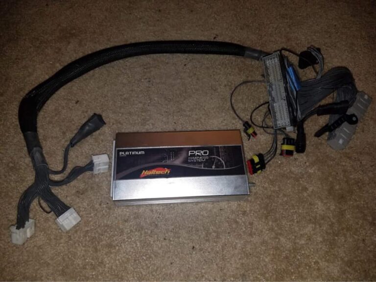
  • Haltech 350z Silver
  • Patch Harness
  • Haltech Dual Wideband/Controller with a VEI Gauge!
  • Zero issues with the unit going full stand-alone since emissions will no longer be an issue.
  • Has been in my car for 2 years.
  • Can check out my live video on here back in January.
  • Asking for $1k shipped!

Loading

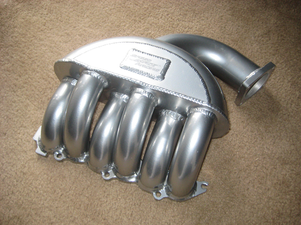
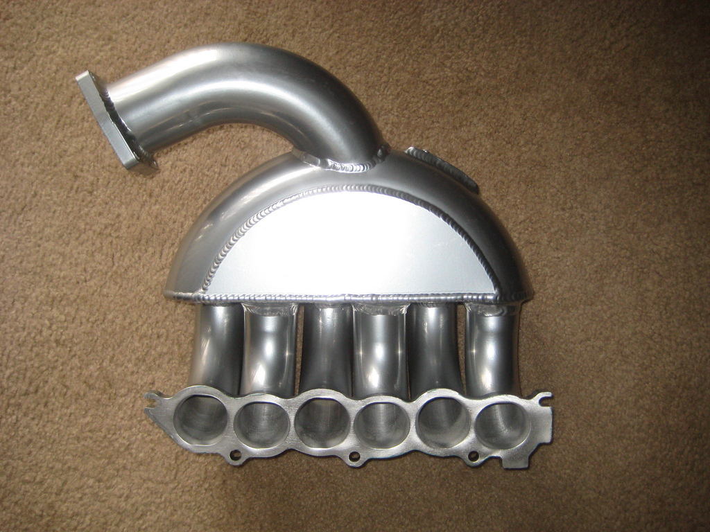
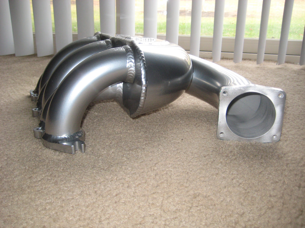
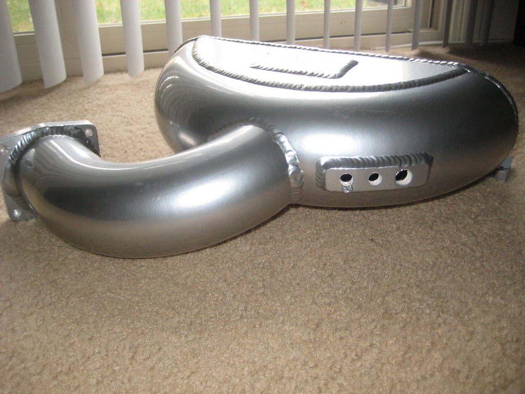
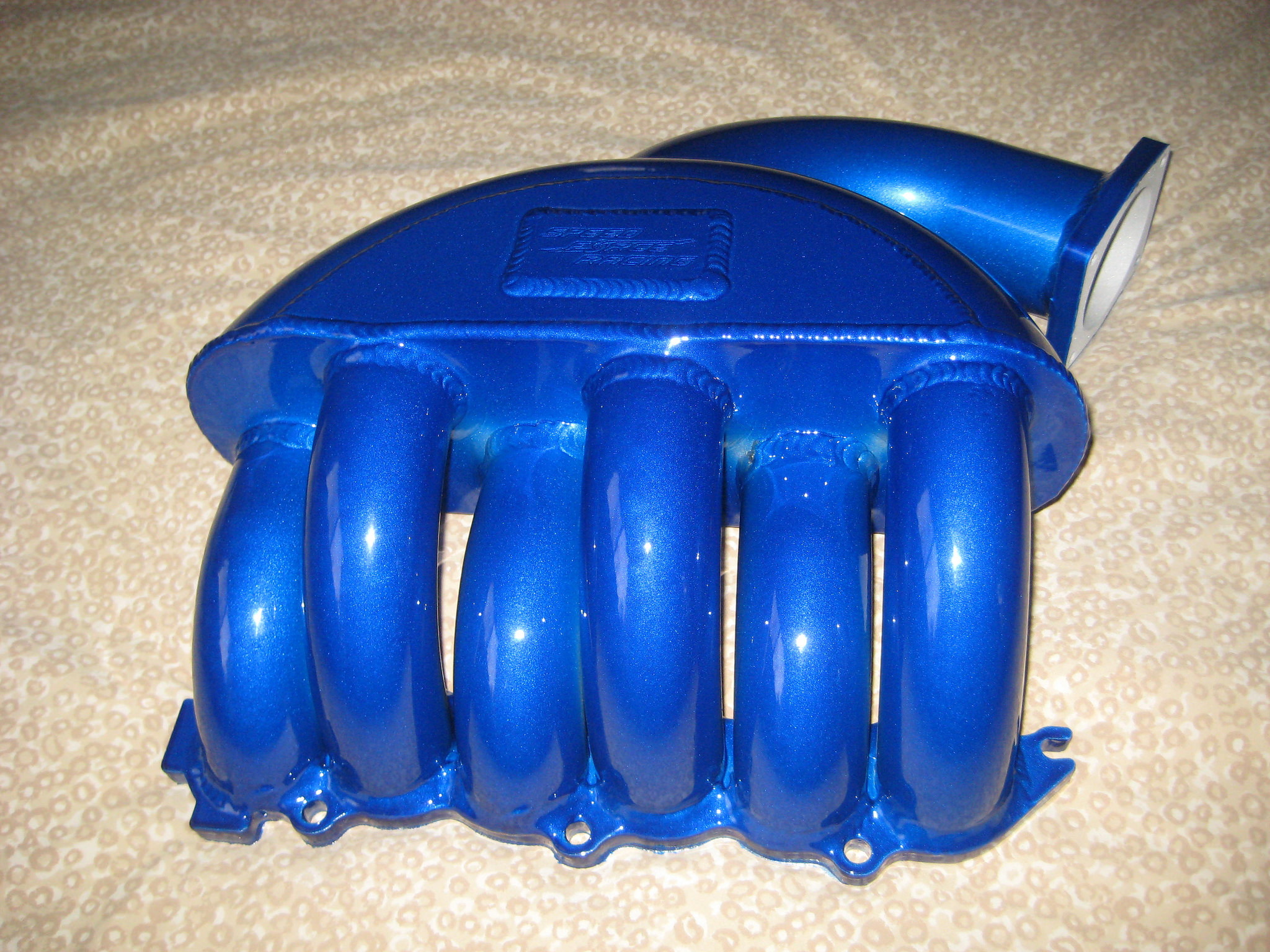
If you want to add an easy 25WHP to your Altima or Maxima then look no further. Our SFR high-velocity manifold is an easy bolt-on and adds 25WHP to an NA car and up to 50WHP on turbo cars. We also offer an aluminum engine cover that goes with it to really dress up the engine We also offer the intake manifold for the later models Altimas and Maximas.

Nissan Club

I was fortunate enough to have the first SFR High-Velocity Manifold put on a N/A vq35. From what Tim at Speed Force Racing told me this manifold is slightly different from the manifold made for forced induction cars.

I have had the manifold for months. When I first received it I was impressed with what I saw. The design is wicked and looks waaaayyy better than stock. It took me a while to slap it on at first because I had to find and purchase the correct barb fitting to hook up the vacuum hoses. At first, the installation was a bit time-consuming because I didn’t know what I was doing. I have installed the manifold on and off about 6 times already so installation for me is under an hour.

The sound is pretty cool. At low revs during soft acceleration, you hear a humming/growl from under the hood. Under hard acceleration, the engine sounds great! it isn’t loud and obnoxious. It’s more of a deeper growl, nothing too crazy or far from stock, but noticeable.

At first, I could only go off of the butt dyno and my butt dyno liked what I felt. To me, the mid-range was increased a lot. I knew the torque was increased a lot (dyno showed 10wtq at peak). Up top, the car felt great as well. My car just easily pulled to higher RPMs. I could definitely feel the car breathing MUCH better. Even while cruising at lower RPMs the car had sooo much better response.

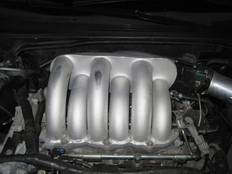
Here are some pics of what it looks like on my car:

Some graphs got mixed up at the shop but I managed to get the most important ones. The graph shows the highest dyno from the stock manifold with the highest dyno with the SFR manifold. the other graph has the highest stock vs. a couple runs with the SFR manifold but also shows the torques as well.

I picked up almost 30whp at redline alone.

I was amazed at how much power was picked up at redline. this isn’t your average SSIM dyno graph only showing gains up top. You can clearly see there are gains on the ENTIRE powerband. Peak rose 5whp (wish it was more). What’s important here is the area under the curve. midrange you can see ~12whp gains as well!

I like this manifold very much! yes, it’s not a cheap mod but for the overall power, it’s worth it. It adds power where cams don’t and cost half the price. Plus install isn’t that hard. To me, it was well worth the money spent.

Additional Reference Photos

Loading

Issue:

Hey guys. Strange problem here and I’m hoping this has happened to someone before so you know how to fix it. My rear brake lights stay on even when the car is turned off. The key is out of the ignition and they just stay on, thus leading to my battery dying quickly. Any suggestions? I actually pulled the tail light fuse and they still stayed on! Any suggestions would be great.

Cause:

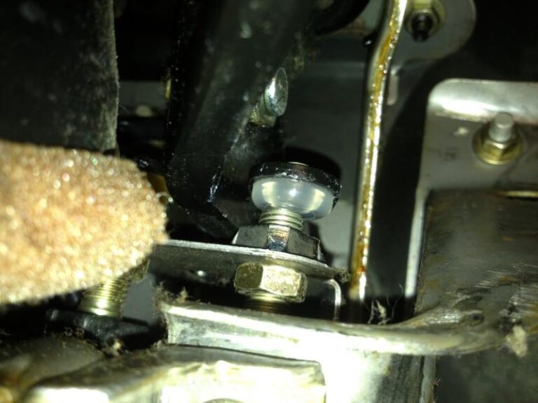
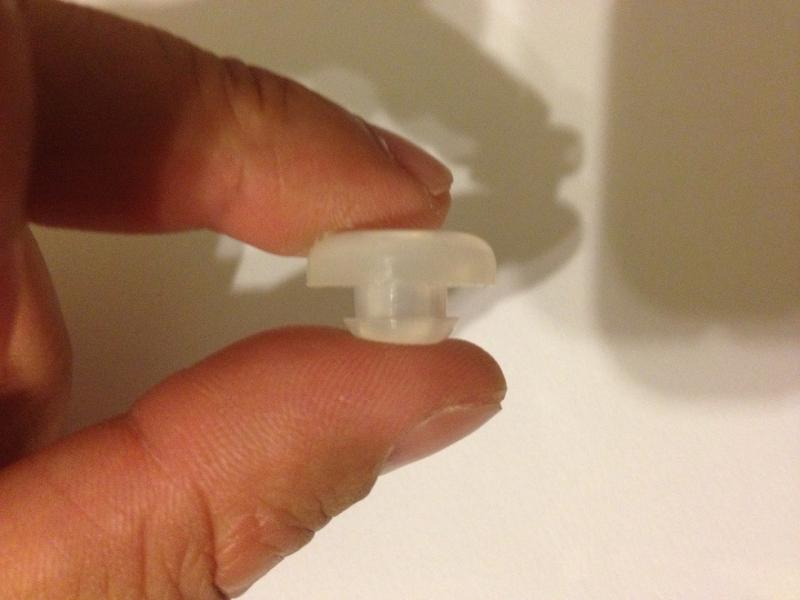
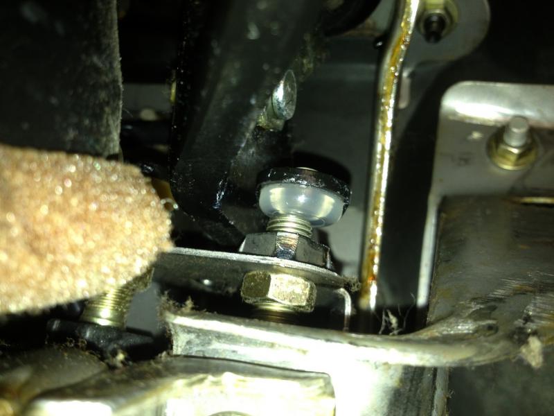
The same thing happened on my 1st gen. The brake pedal itself has a little rubber piece in it that brake light switch contacts and over time it dries up and breaks and falls out.

Resolution:

Yes, there are 2 stoppers – one for the brake light switch and the other for the cruise control disconnect switch. The two switches have nothing to do with the other one.

Additional Fixes:

  • A penny with electrical tape worked for me.
  • This happened to me as well. I tapped a penny with electrical tape to my brake pedal where the plastic button use to be for the brake light switch.
  • Yep. Found both the brake light and cruise control rubber pads on my floorboard. O’Reilly sells rubber bumpers for $2.49 that fit perfectly. Part Number 456230BP.
  • The part number for the 1996 model is 46584-S0100. I would recommend bringing your VIN number to the local dealer to make sure you got the right part. I said this because, for rubber-stopper replacement, there is another part number: 46584-5P010. It’s in black color with a much smaller end and it doesn’t fit my 1996 model.

Part Info:

Nissan calls the rubber bumper thing “Stopper-Rubber”. there are 2 part numbers listed for it but I don’t know what the difference is. They are:

  • 46584-S0100 list price $3.23 Used on 1995 through 1997
  • 46584-5P010 List price $14.05 Used on 1996 through 1999

Loading

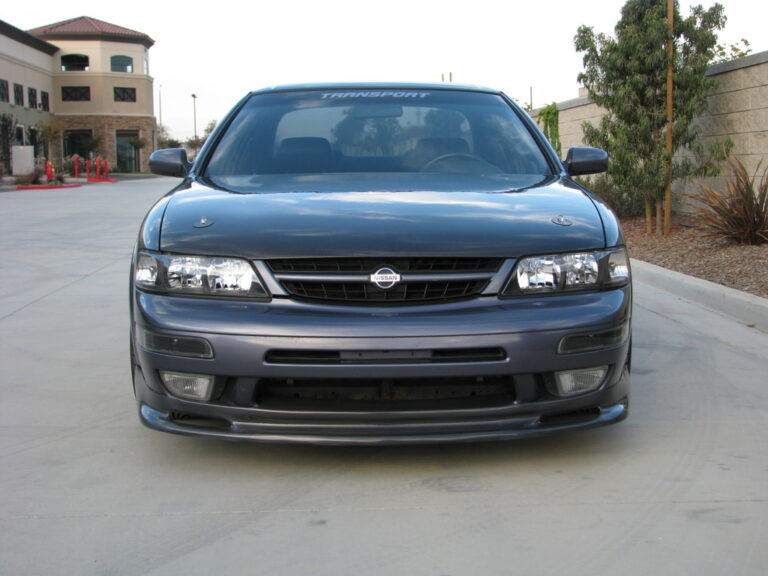
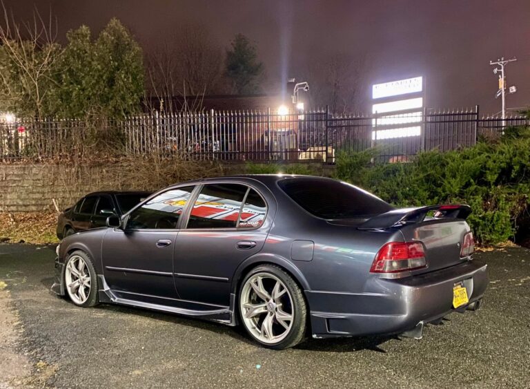
Owner: Eric Yam

Year: 1999
Model: Maxima
Color: Charcoal
Transmission: 5-Speed Manual
Trim: SE

Mod List:
  • 5-Speed Manual w/ VLSD Transmission
  • 3.5 Motor w/ 3.0 Timing
  • 262 Cams
  • Rev-up Oil Pump
  • ARP Rod Bolts
  • ARP Main Bolts
  • ARP Head Studs
  • Cosworth Head Gasket
  • Cattman Headers
  • Cattman Catback
  • Test Pipe
  • NWP Plenum Spacer Kit
  • Kinetix Intake Manifold
  • Pathfinder Throttle Body
  • Short Ram Intake
  • Southbend Stage 2 Daily Clutch
  • ACT Street Lite Flywheel
  • E-Manage Ultimate
  • Mishimoto Radiator
  • Mishimoto Rad Hoses
  • Mishimoto Thermostat
  • Brembo Acura TL Front Calipers
  • BC Racing Coilovers

Loading

Community Member Credit: asand1 / maxima_se007

Important Note: This should really be used as a temporary solution. The proper fix is to replace either the knock sensor itself or the harness which is known to go bad. Most people do both at the same time.

Resistor: 470K

Order Link: https://www.radioshack.com/products/radioshack-470k-ohm-1-2w-5-carbon-film-resistor-pk-5?variant=20332249541


Instructions

  1. Disconnect the knock sensor at the easily accessible connector. (you can find this by looking at the knock sensor and following the wire and wire loom towards the engine bay.)
  2. Buy a package of 5 one megohm resistors at radio shack for $0.99. (Part #: 271-1134)
  3. Take 2 of the resistors out and put them next to each other (side by side) and twist one wire on each resistor onto the one next to it from the other resistor. You now have a 500k resistor. (you can buy a 470k resistor, but i felt this would give truer results to knock sensor specs seeing as how a good knock sensor is between 500k-600k ohms.) DO NOT twist only one side, creating a 2000k ohm resistor (by going —(***)-x-(***)— (imagine the —(***)— is a resistor and x is a twist) that is the wrong way, just imagine you have to make one resistor unit out of two. If this is confusing, just get a 470k resistor.
  4. Insert one twisted wire (single wire if using 470k) into one receptacle of the connector in the engine bay (not the one leading to knock sensor) and the other twisted wire (single if using 470k) into the other receptacle on the same connector. You are eliminating ANY use of the knock sensor or the wire connected to it.
  5. Use electrical tape to keep it secure and to avoid any short-circuiting.
  6.  Enjoy some extra power (if your knock sensor was bad), but look out for knocking which can be potentially harmful to the engine if excessive.
  7.  I would recommend you check your codes before doing this to find out if your ks is in fact bad. I would also use this as only a TEMPORARY solution until a new ks is purchased and installed. Use the highest octane you can get too, because it will help in the prevention of knocking.

Installation Photos

Stock Sub-Harness

Notice the KS Sensor attached at the right. You will want to use the end at the left. Strip off the electrical tape and wire loom. Then strip the tape from all the connections. Clip the black wire where it is crimped to the shielding. Pull the shielding from the clear wire. Strip the black wire about 1/4″. I used a 16Ga butt connector cut in half, and solder to connect to the 470k resistor. Now clip the other end of the resistor and the clear wire even. Strip about 1/4″ from clear wire and solder using the other half of the 16Ga butt connector.

It should look like this now.

Now use shrink tubing to protect. I folded the end over and added another short piece of tubing.

Now put the sub-harness connector back on its bracket and plug the engine harness plug back in.

Loading