

Last Updated: 09/06/2025 @ 03:40 pm
Member Credit: Streetzlegend via FastMaximas.com
This is a topic that a lot of people tend to avoid. They find it difficult before sitting down and trying it or looking it up; its treated like math in a way. I’d like to give an overview of what engine tuning is in layman terms. I will go over an engines mechanics, fuel, timing, sensors and tuning devices.
Engine Basics
An engine is a block of metal that has holes(cylinders) 95.5mm in diameter in the case of a VQ35. Below the cylinders inside the block there is a separate rotating piece of metal called a crank. Inside a cylinder there is a piston that moves up and down, pressurizing as they go up since the top of the cylinder is blocked off by whats called a head. Air and fuel is sent into the cylinder through the head and a spark plug that is screwed through the head and into the cylinder ignites the mixture.
This explosion pushes the piston down into a rod that’s connected to the rotating crank. The stronger the explosions within the cylinders the more force there is to rotate the crank. The crank is connected to the transmission which then sends the torque to the wheels and moves the car.

Fuel and Timing
The fuel entering the combustion is controlled by the injectors spray. The rate in which the injectors open and close and the duration while open determines the amount of fuel delivered. The injectors are controlled by the cars computer, the ECU(engine control unit or module). When you hear the term “timing” being mentioned, this is referring to when the spark plug fires and ignites the compressed air and fuel mixture.
As the piston travels up the spark plug fires before the piston has reached the top (TDC – top dead center). By the time the piston reaches the top and starts going down thats when the mixture is starting to fully ignite. The goal is to have the combustion event occur right after the piston reached TDC but not too late that the piston is already traveling downward too far. When combustion occurs before the piston has reached TDC thats when you break parts because the combustion’s pressure will be pushing down while the piston is still going up.
Engine Knocking
Something important you have to know if you care about the longevity of your VQ or any engine. Learn what knocking sounds like. Knocking sounds like marbles hitting each other repeatedly. You may have heard this when putting a lower octane fuel than a car asks for. The higher the fuel octane the higher the pressure it can withstand before exploding therefore more timing could be advanced. That means having the combustion closer to TDC once the piston starts to come down. If the fuel octane is too low for the pressure being generated in the cylinder then random combustion events will occur without the spark plug even firing.
On Maxima’s and most cars, engine knock is detected via a knock sensor that is mounted in the middle of the engine between the two heads. This sensor tells the ECU when knock occurs and the ECU makes proper adjustments in timing to reduce the knocking.
In the next article I will talk to you about sensors and tuning devices.

We have gone over the basic function of an engine, timing, fuel and knocking. Now we’ll start getting deeper into MAF sensors and modifying their signal.
Sensors
The ECU knows the position of the crank by the crank sensor. It knows the amount of air coming in by the MAF(mass airflow) sensor which measures air density. The MAP(manifold absolute pressure) sensor measures the air pressure. These sensors combined help the ECU determine what changes in timing and fuel to make.
Knock Sensor
Like most engine sensors, the knock sensor is very important. This sensor is responsible for detecting knock or random combustion events which generate a pinging/knocking sound like I mentioned before; marbles hitting. You can mimic this sound by tapping the engine block with a screw driver lightly, the knock sensor would pick it up.
When you have a condition that is too lean and or there is too much timing you will tend to experience knock and that is when the sensor sends a signal to the ECU. The ECU then makes timing adjustments such as retarding the timing in order to not repeat the knock it just picked up. On a Maxima, the ECU does not do a good enough job at reducing timing when knock is present, this is why it is important to do something about timing once you start to modify your Maxima for more power. Side note, when you hear a near stock VQ35 knocking, it is likely that there is oil present in the intake manifold and in the combustion due to poor PCV valve design(a catch can is needed).
There are devices that can be programmed to make adjustments to the timing once knock is detected. One system is the J&S Safeguard which is an old school device yet extremely important in the my turbo 97. Once any sign of knock is detected you can choose to reduce certain amount of timing degree’s depending on the strength of the knock. Devices like these do a much better job than the factory ECU which only reduces a small amount of timing when knock is detected. Nowadays standalone ECU’s handle this much better as well as newer factory ECU’s.
MAF
The common MAF has a hot wire suspended in the air inside the intake airflow path. The temperature of the wire affects how much current flows through it. When the wire is hot there is more resistance and therefore less current flows (electrical current moves easier in the cold). The wire is cooled down as air flows through it, reducing resistance and increasing how much current flows through. The resistance measured is converted to a voltage value between 0 and 5.0 which is then sent to the ECU.
You may have heard of the MAF size being increased or swapping to a different one. This is because the MAF is calibrated for a specific air flow and once you start to exceed that the MAF will no longer read additional air.
There are ways to solve this for example once the MAF has maxed out and its sending the ECU 5v, you can then use the MAP sensor to adjust your fuel and timing. Another way could be to increase the size of the housing where the sensors wire is. You can also put a MAF that is designed to read higher amount of air. For my 1997 I use a Nissan Z32 MAF because it is designed to read more air than the factory 4th generation Maxima. The Z32 MAF will read roughly 550WHP worth of air. At about 18psi with a 66mm turbo I see the MAF reading 5v.
Tuning Devices
Engine tuning is controlling the output of the engine by adjusting air, fuel and timing.
Air Fuel Controllers (AFC)
The most common method of making adjustments to the fuel is by using an air fuel controller (AFC). You may have heard of piggyback. This is referring to a device that is connected between the cars ECU and the engine. The piggyback device can be programmed to adjust the signals going to and from the factory ECU. For example if the ECU is sending 50% duty cycle to the injectors, the device could modify that and add or subtract duty cycle. This method of tuning allows you to keep the factory ECU while still being able to tune.
With the common AFC you are limited to being able to control only the MAF signal. By modifying the MAF signal the ECU is receiving, you are able to control the amount of fuel being delivered. This is a great way to make small adjustments to a lightly modified Maxima. One side effect of controlling fuel this way is that when you remove fuel you are increasing timing and when you add fuel you are retarding timing (less timing advance). Technically you can advance timing this way on an all motor Maxima and gain a few HP, as long as the higher timing is not causing knocking; for example ~200WHP/WTQ on an all motor automatic 97.
Advanced Air Fuel Controllers
More advanced air fuel controllers are those that not only can modify the MAF signal but they can modify nearly all engine related signals. For example an Emanage Ultimate can modify fuel injector duty cycle and duration, ignition timing, throttle position, and can read and monitor many inputs. The next level after this would be using a standalone ECU.
Standalone ECU
Standalone ECU’s are computers that replace the car’s factory ECU. This is generally the ideal method of tuning as it gives you total control while the air fuel controllers only modify the factory ECU’s input and output. Standalone’s tend to be far more expensive than air fuel control so generally you see more air fuel controllers used on home built cars.
In the next article I will go over logging and examples.

We have gone over sensors and the type of devices used to tune in part two of this series. Now we’ll take a look at some examples, i’d like to show you what I do to tune.
I would like to note that this is a general explanation of what the tuning process is about and not specific to a tuning device. The same steps can be applied to most systems; the concept is the same.
Logging and Tuning AFR
o2 Sensors
Oxygen (o2) sensors are a critical component to the entire tuning process. They read how much oxygen you have in your exhaust, that is the air to fuel ratio (AFR). 14.7:1 is called stoichiometric and this is considered the ideal mixture of air and fuel in order to have an efficient and complete combustion; 14.7 parts of air to 1 part fuel.
Richer means there is more fuel and Leaner means there is more air and less fuel.
The leaner the mixture is the higher the combustion temperature and therefore more prone to causing damage. Richer means cooler which is why most turbo VQ’s run at an AFR of 11.5:1; not only in VQ’s but most turbo engines in general.
11.5 AFR is only an estimation on turbo, supercharged, and nitrous cars. This is why tuning your engine is ideal instead of using generic tunes from others car.
Tuning
Logging is the most important part of tuning in my opinion. Without it theres nothing you can do but guess what the engine is doing.
First I recommend a track or Dyno for safety. You want to get in a gear that is long but not your highest gear. On a 4 speed auto, 3rd gear is ideal and 2nd gear is long enough to be usable to tune with lightly modified Maxima’s.
Closed Loop and Open Loop
Most of the time the car will be in closed loop below 3k RPM, that means the ECU will be reading the o2’s and making adjustments so that the output AFR is 14.7 for a clean and complete burn. Above 3k RPM and above around 30% throttle the ECU goes into open loop and no longer is using the o2 sensors for feedback. Once in open loop mode the ECU is making adjustments based on tables in the software, usually called Maps.
The MAF and TPS(throttle position sensor) among other sensors are used during open loop to determine the fuel and timing (the o2’s are not used). The 3k RPM and 30% throttle are just estimates and not exact values used by the ECU, there are other factors that determine if the ECU operates in open and closed loop such as engine start up, faulty readings from the o2’s, high coolant temperatures, etc…
On automatic transmissions, the car is ran with over drive off and revved to above 3k before going wide open throttle (WOT) so that it does not downshift; if you go WOT below 3k rpm the transmission will downshift.
Logging and Adjustments
To provide context, I will go over some of the logs from my own Maxima when it ran 11.3 and 11.2 in the 1/4 mile.
For reference below are some details about the car and a video from this day:
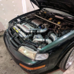
1997 VQ35(VQ30 Timing) Automatic.
66mm Turbo at 20-22psi.
Nitrous for launching.
Using an Emanage Ultimate.
The 11.3 run was using all 4 gears.
The 11.2 only 1st and 3rd gear were used; 2nd and 4th gear failed before this run, however the logs still are relevant to our topic. We’ll use the 3rd gear portion of the logs.
Once you’re cruising at your desired RPM such as 3k, you hit record and do a WOT run till redline or the maximum RPM you plan to take the engine to on a regular basis.
Here we have the log to the 11.3 1/4 mile run:

In this log I have selected 6,300 RPM in 3rd gear (the red vertical line). On the right you can see the values for that moment which shows an AFR of 10.5 and 20psi. You want to look at the AFR curve and make sure it is within your desired target AFR, lets use 11.2 as our target.
When your intent is to make adjustments you usually have your tables open such as the fuel table for example. The table shows RPM on top and PSI on the left. So I look at 20psi-21psi on the vertical axis then 6300 RPM on the horizontal axis and where they intercept is the cell that is being used to make adjustments to the fuel. Here we see 22.2%, this means its adding 22.2% to the duty cycle the ECU is giving out to the injectors. Remember that with a piggyback system you are modifying the ECU’s output, its not creating the outputs like a standalone.
So at this moment I am thinking that 10.5 is too rich and I want to make it leaner. I decrease the percentage from 22.5% to 21% in that cell so that it provides less fuel. I look at the rest of the AFR curve and make sure that there are no other areas that are too far off my target; too rich or too lean. You’re ready to do another run after you save your map and export it to the ECU.
Here we have the log to the 11.2 1/4 mile run:

For this run you can now see that at the same gear, RPM and PSI we now have 11.0 AFR. So we have successfully made the AFR leaner by .5. In the case of the Emanage you can see the adjustment value being applied highlighted in blue in the right labeled (I/J Adjustment Map) which is generally the value you entered on your table.
When entering values in the cells keep in mind that the RPM’s and PSI are constantly moving, so the computer may not be using the exact cell you have entered a value for. Instead, it uses the average of the surrounding values (interpolation). For example if you are between 6,000 and 6,300 RPM, the software will use the interpolated value thats between those two cells.
Now that you have seen the change in AFR due to your map change, you can repeat the process till you have achieved your target AFR.
For part 4 and the final part of this series I will touch on tuning the ignition timing.
![]()
Comments are closed.