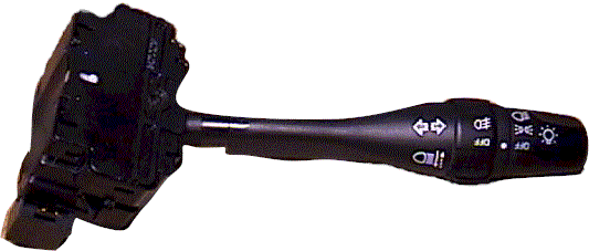
About one year ago (2000), I was driving back from work, and I saw a single streamer of smoke coming up from my steering column. I immediately tried all the switches on the steering column, thinking that I will find out which switch has gone bad, and maybe I will make it stop.
Well, everything worked just fine, and the smoke did stop. A month later the same thing happened, a single streamer of smoke.
After the first time I parked my car in the garage thinking “I hope that I don’t set my garage on fire if she lights up.” It never happened again.
In August 2000, when I signaled to turn left, after the turn was completed the signal would cancel, but the turn signal relay would click about twice the usual speed, “click-click-click-click-click” Luckily for me the turn signal light did not flash, it was just the relay.
I removed the relay, and opened it up. It is not your typical relay. It is a relay with printed circuit board on the side. I noticed that the circuit board was cracked, and it looked like a few traces may not be in full contact. I added a little bit of solder, thinking that it was now fixed. I was wrong.
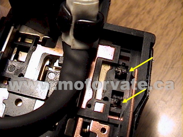
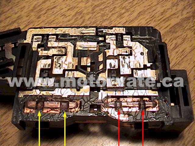
Now it is March 2001, and I noticed that my turn signal was not “smooth” like I remembered it. It was very notchy. I removed it from the steering column, and saw this:
The YELLOW ARROWS point to some melted plastic. The RED ARROWS point to what the contacts should look like. The yellow arrows in the right picture above, show little plastic “parking” islands are melted. This made the contacts sit lower, and they were only touching a little, causing a little current to flow through the relay. The relay senses current, via the built in IC, and makes the relay pulse, but because the current is very small, it flashes faster. (just like when you have a burned out turn signal bulb, the flasher goes faster)
Anyways, this is where the smoke came from. YEA! I found it. My car is not going to burn down!
I tried to “file & fix” the contacts, but it did not work.
I called up North End Nissan, and 1 day and $71 later I had my turn signal back to where it was, nice and smooth, with no harsh clicks.
Problem solved in 10 minutes, but it took over a year to figure it out.
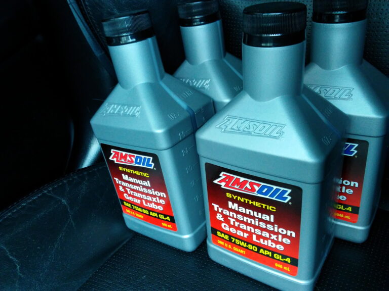
For the average automobile, there are two types of API Service for gear oil:
GL-4
GL-5
The “API Service” has nothing to do with viscosity. Viscosity is basically the “thickness” of the oil at winter (75W) temperatures, or summer (80) temperatures. Some typical examples as 75W80, and 80W90. Consult your owner’s manual for what is best for your vehicle, in your climate, with your driving conditions. An “API Service” is a specification that defines flash point, viscosity, color, pour point, the amount of extreme pressure additives and others.
Generally GL4 is for transmissions from European and Japanese auto manufactures. GL5 is usually for transmissions and differentials from North American auto manufactures.
As with most specifications, the newer the better. So GL-5 is better than GL-4. GL5 has about twice the extreme pressure (EP) additives of GL-4. Due to these additives the transmission must be designed for GL-5.
If you buy GL-5 gear oil, and put it in your GL-4 transmission you are not doing your transmission a favor. In some cases the GL-5 gear oil can be “too slippery” and the synchronizers in the transmission will slightly “crunch”, as they are not rotating at the same speed. GL-5 also has twice the extreme pressure additives of GL-4, and these additives can corrode certain “yellow” metal synchronizers. Think about that!
With this in mind, if you have any transmission work done, insist on GL-4, if your owner’s manual calls for it. My 95 Maxima calls for GL-4, and I had a bearing failure (not related to GL-4 / GL-5, but an excessive preload) When I asked them what kind of oil did they put in the transmission, they said “Esso 75W-90.” I then asked to see the container that it was in, and right on the front it said GL-5. I asked them, “Is it OK to use GL-5 in a car that is designed for GL-4?”, and their answer “Yes, it is one better” They also said that the gear oil they use is approved by Nissan. I called Nissan HO, and asked them if GL-5 can be used, and the tech on the line told me, “GL-4 should be used.” Hmmm.
After paying $1200 to rebuild my transmission, I now had buy GL-4 gear oil and change it myself. Not a big deal, but to my surprise no one, and I mean no one sells GL-4. I tried eight local auto stores, and they all sell GL-5. No GL-4! To make a long story short I found some GL-4 in Rochester, NY and replaced the GL-5. The shifting improvement was immediate. With the GL-5 when I would shift I could feel the syncronizers hitting just before the car went into gear. With the GL-4 it was like just shifting a gear, with the usual amount of “snick” (aka notchiness)
The following is a technical note from Pennzoil, P-21-B which talks about GL-4 & GL-5
(The below text is found on page 2)
GL-5 GEAR OILS ARE NOT INTERCHANGEABLE WITH GL-4 GEAR OILS.
The extreme pressure (EP) additives in most gear oils contain sulfur-phosphorus compounds that can be corrosive to certain “yellow” metal components such as copper and brass synchronizers.
Always follow your owner’s manual for the correct lubrication recommendation.
Simple rule: RTFM (read the friggin manual) and follow it.
The manufacture knows what is best, the dealer may not.
In the maintenance section of the owner’s manual it does not mention changing the power steering fluid. However, for many years I have always changed it every year. With the constant thermal cycling, and the stress of being pressurized to 1,266 psi, it must slowly break down. The following procedure cost less than $4.00, and takes 15 minutes.
Use a turkey baster to collect the old power steering fluid.
Transfer it to a container to be recycled. This process will need to be repeated a few times. You can remove most of power steering fluid from reservoir this way. A baffle at the bottom prevents us from removing it all.
If you want to empty the power steering reservoir, disconnect the hose with the arrow. The entire contents will empty out, but it is difficult to catch it in a container due to the A/C line. Reconnect the hose, and tighten the hose clamp.
Fill the reservoir to the COLD MAX line using Dexron II or Dexron III, depending on the year of the car.
Put the cap back on and you are done.
This simple procedure will change about half the power steering fluid, (More if you remove the hose at the bottom of the reservoir) and should ensure a long life for your power steering pump, and steering rack.
Sooner or later you will have to replace the clutch on your Maxima. Since I was removing my transmission to replace a bearing, I decided to change my clutch. It had 145,000* Km on it and it still worked well, but since I had the transmission out, I could not resist.
*The clutch was changed at 50,000 Km under warranty, for a noise.
First you must remove the transmission. Then you will see your clutch as above. (make sure to support the engine, as it only has only one engine mount holding it).
The old clutch has been removed, and the flywheel has been lightly hand sanded with 180 grit sandpaper to remove any foreign material that may be on the flywheel.
Close up of the old pressure plate where the throw out bearing pushed on the diaphragm. The groves are normal for the mileage on the clutch. Right:
The friction disk side of the clutch and the friction disk.. Notice the marks on the pressure plate. This is due to over heating from racing or even stop and go traffic. The friction disk only had .017″ before the rivets would gouge the flywheel.
The friction disk side of the new pressure plate.
The old throw out bearing (foreground) and the new throw out bearing. (background) Always replace the throw out bearing when the clutch is being replaced.
The new throw out bearing and clutch fork installed. Notice there is no machined area on the end of the input shaft, which usually fits into the Back of the crankshaft.
The bearing is known as the pilot bearing.
In the middle of the picture you can see the pilot bearing. In this application, the bearing is there, but it is not used! (look at the input shaft, there is no machined area at the beginning of the shaft)
Old clutch
New clutch
With clean hands, place the new friction disk on the pressure plate. Lift up to the flywheel, and tighten the clutch bolts finger tight. Insert the clutch alignment tool into the hole in the clutch (where the input shaft will go) until the tools stops firmly in the pilot bearing. Tighten the clutch bolts in a diagonal pattern to spec.
Summary
It is not difficult to remove and replace the clutch in the Maxima. I only need one special tool, a $17 clutch alignment tools. In the past on my 91 NX 2000, and my 83 VW GTi, I have used a broom handle cut down to measure about 8″ to align my clutch. This time I wanted the to use the right tool.
Right now, the typical cost to replace a clutch on a Maxima is about $600. (at least!)
My parts cost were: friction disk $120, pressure plate $170, and throw out bearing $48, from the local Nissan dealer. That totals $388 with tax (15% !)
If you do the quick math, I saved $212! That money will go to my cat back exhaust. Vrooom!
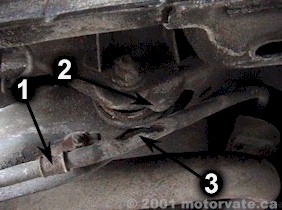
When some mechanics put your Maxima on a hoist, sometimes the “lift arms” of the hoist bend the parking brake cable bracket. (item 1)
This causes the cable to pushed into the very front pivot point of the rear suspension (item 2)The result is a split parking brake cable (item 3), where salt and water can corrode the cable causing it to seize.
Solution:
Slightly bend the parking brake cable bracket (item1) away from the rear suspension pivot point.
Summary:
Simple fix. As you can see on mine it was too late, the cable has been cut, and dirt and debris have probably got in the cable.
Changing your coolant on a regular basis is very important to the longevity of your engine. With normal use, the corrosion inhibitors loose their effectiveness. Nissan recommends that AFTER the first 96,000 KM replace the coolant every 24 months, or 48,000 KM. The procedure that I am following is detailed in the Nissan Maxima’s Owners Manual, in the “Do it Yourself section.”
The engine must be COLD! Do not try this on a WARM or HOT engine. You may warp the block or the heads!
First we must open the valve in the heater core, to allow the coolant to drain out of it. There are two way to do this, depending on the type of climate control you have.
Manual Climate Control
Turn the ignition key to “ON” (one position before “START”), and put you heater control to the maximum hot position. Turn the ignition key back to “OFF”
Automatic Climate Control
If you have the Automatic Climate option (as shown below) you need to do the following to open the valve in heater core:
Turn the ignition switch from the “OFF” to the “ON” position
With in 5 seconds of being switched “ON” push the “OFF” button on the climate control for at least 5 seconds.
Press the “HOT” button 3 times
Press the “DEFROST” button 2 times. Code 43 will be displayed.
Wait 10 seconds before switching the ignition to “OFF”
I like to use a pan like the one shown to catch the coolant. You can use a pail, but then you may have to jack up the car in order to get the pail to fit under the car.
This is the PLASTIC drain plug that is in the bottom of the radiator. Use a large Phillips screw driver to remove it.
Coolant draining from the radiator into the container.
Remove the radiator cap.
Remove the clip on the radiator, and pull off the hose. This hose goes to the reservoir tank. Right:
Here is an inside view of my reservoir tank. It is very dirty, and needs removed to be cleaned. Once the hose is removed from the rad, the reservoir bottle can be pulled out of it’s bracket. Flush out the reservoir with a hose, and maybe a small brush to get it clean. Reinstall the coolant reservoir, hose and clamp.
INSET Photo: Cleaned reservoir bottle.
Front coolant plug. This is used to drain the coolant from the front bank of cylinders.
Rear coolant plug. This is used to drain the coolant from the front bank of cylinders. Your owners manual has a nice picture to show you their location.
These plugs are VERY difficult to access! If you remove the Y-pipe (factory or aftermarket) you will have more room. Remove the plugs, let the coolant drain. Use thread sealer on the threads, and tighten to 13-15 foot-lbs
-OR-
Don’t remove these plugs. At most the engine may contain about 2 liters of coolant. When I added coolant the rad took 5 liters (total engine engine/rad capacity is 7 liters, plus 2 liters for the reservoir). Most of the coolant is being changed (5 out of 7 liters), and from now on, I will change my coolant using this method every year.
What ever you decide to do, you should flush the rad with water. This will remove any sediment and the old coolant. To do this, simply put the water hose in the filler neck of the rad, let water flow thru the rad, and exit the bottom. Make sure that you capture all the coolant in a container, for recycling.
Install the rad drain plug. Make sure the rubber washer is in place. (indicated by arrow)
Check the rad cap for any tears in the rubber. Using a clean rag, wipe off any foreign matter on the rubber seal. Gently lift up the metal “hat” as shown by the arrow, and wipe off the “hat” and rubber under the “hat” This is the valve the allows coolant to enter the rad, from the reservoir bottle as the car cools.
Make life easy for yourself. Pre mix a 50/50 mixture of coolant and soft water. This will protect you from -37°C to 129°C.
Pour in the 50/50 mixture S-L-O-W-L-Y. This will allow time for air to escape.
Install the radiator cap.
Start the engine, and let the car warm up, until it reaches operating temperature.
Race the engine 2 or 3 times in neutral. Keep an eye on the coolant temperature, just incase the motor starts to overheat.
Let the engine completely cool down.
Top off the rad to the bottom of the hole for the reservoir hose.
Fill reservoir to the “H” mark with mixture of 50/50 coolant and soft water.
Check the rad drain plug for any signs of leaking
Recycle the old coolant
After a few days, with the engine cool, check for leaks, check the coolant level, and check the freezing / boiling point to ensure it meets your requirements. For most of Canada, a 50/50 mix should protect you. (down to –37°C)
Do not leave the old coolant in an uncovered container.
Animals like the smell and taste (very sweet) but it will KILL THEM. Recycle it as soon as possible!
The knock sensor plays a very important role. It listens to the engine. When it hears engine knock it sends a signal to the ECU. (Engine Control Unit) The ECU normally will delay (or retard) the ignition advance. This stops the engine knock, and decreases engine power.
Engine knock can be caused by using lower octane gas than is recommended by the manufacturer, or by over advanced ignition timing. It can also be caused by a “hot spot” in the combustion chamber. During high engine load, some carbon that has accumulated in the combustion chamber can glow red. This can cause the air-fuel mixture to ignite prematurely. This is PRE-IGNITION, and it is the equivalent of taking a very large hammer and hitting the piston before it rises to the top. (TDC, top dead center) This sends a shock through the engine, and the knock sensor “hears” the knock, and tells the ECU.
For the past year, my ECU would have the code 34, knock sensor failure. I would reset the ECU, drive for 5 minutes and the code would return, BUT the check engine light (CEL) never came on. The car was running great, so I didn’t think it was in need of urgent repair, as I ALWAYS use Sunoco Ultra 94.
Early 4th generation Maxima owners were telling stories of amazing increases HP, as measured by the BUTT DYNO. (yes, it was SAE corrected) I wanted to see for myself.
Knock sensor location. It is not very easy to get at. I was able remove the knock sensor WITH OUT removing the ENTIRE intake manifold. My hands were cut up quite a bit, and it was painful, but I was done is 30 minutes. To remove, simply loosen and remove one bolt. Gently pull the knock sensor harness to remove it from the “V” of the engine.
Close up of the knock sensor.
Close up of the knock sensor. This is the bad one, with just over 235,000 Km on it.
Connect the new knock sensor to the knock sensor harness. This will prevent it slipping out of your bleeding hands, and fall to a spot that you can not reach. The red connector at the knock sensor only has ONE wire, however on the other side of the knock sensor harness there are 2 wires. Everything is fine, the sensor has a braided wire shield that is grounded. If the knock sensor falls to the floor, it can be easily damaged. BE VERY CAREFUL WHEN HANDLING THE KNOCK SENSOR.
Tighten the knock sensor bolt by hand, until the it is snug. I had just enough room to get a wrench on the bolt and tighten it. If you over tighten, the knock sensor will be VERY sensitive, and if you under tighten the knock sensor will not se sensitive enough. The factory spec is 15-20 foot-lbs.
The knock sensor is grounded by these two 10 mm bolts. Remove them, lightly sand the connector on the wires and the flat area on the intake manifold, then tighten the two bolts. This will remove any corrosion.
Any Difference?
After a few days of driving, the car pulled a quite a bit harder. It now has more power in the lower RPM range (<3,000) Is this possible?
Yes. When the ECU is first powered on, it tests all sensors. When the knock sensor would fail, then it uses a “safe table” which retards the ignition advance slightly. This prevents the engine from knocking, as the “safe table” has values for low octane gas.
When the ECU started up, and saw a good knock sensor, it took time to optimize the ignition advance. The ignition timing advances very slowly waiting for some slight knock. This is how the ECU figures out the octane you are running. HOWEVER, if knock is detected, the timing is retarded VERY, VERY fast. This reduces the incredible stress of knock on your engine. This process repeats over and over.
Summary
If you have a trouble code 34, and your car is 4-5 years old, replace the knock sensor. Don’t forget to clean the ground connection of any corrosion.
A common problem on the fourth generation (1995-1999) Maxima is a leaking oil pressure switch. Mine has had a slight leak for the last 3 years. The leak was so small that it would never drip, the oil would just “sweat” around the switch. I kept an eye on it at every oil change, or anytime I am under the car to make sure it was not leaking more.
When I was under the car to change my alternator, I noticed that the underside of the car by the oil pressure was slightly wet with oil. It is now time to replace it, before it gets any worse. I went to Car Quest and paid just over $20 for it. (I later found out that it is $12 at Canadian Tire)
It is very easy to install. It is better to replace it when you have removed the oil from the car. (like during an oil change) Otherwise, you need to be quick to remove the old switch, and install the new one to reduce the amount of oil that you loose. (It pours out quite quickly!)
The new oil pressure switch.
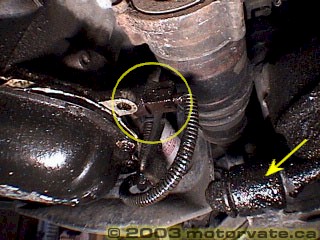
The old switch before it was replaced (yellow circle). Notice the oil on the lower control arm. (yellow arrow)
Remove the rubber boot, and gently pull on the connector to remove the wire.
Switch with boot, and connector removed. Notice the oil drip on the bottom of the switch. (yellow arrow)
You will need some thread seal tape, to ensure the new switch does not leak.
Simply wrap it around the threads in the direction OPPOSITE direction of the threads. This will keep the tape from trying to “bunch up” as you tighten it.
Here is the new switch. I used a channel lock to carefully tighten it. You can purchase a special socket for $6 (US) at AutoZone, When I replaced my switch, I did not drain the oil. (it was 3 days oil) With the engine full of oil, you must be quick to remove and replace the switch as the oil pours out quite quickly.
Attach the electrical connector, and push on the rubber boot.
The finished job.
As you can see, this is a simple job. It should not take more than 30 minutes. I would recommend replacing the switch as soon as it leaks, because if it it leaking a little, it could easily leak a lot. In a worst case situation, your could loose all your oil and seize your motor for a $20 part. The $20 is money well spent. (In the US the cost is about $8)
With any front wheel drive car, after a while the constant velocity (CV) boot will have to be replaced. This may be due to the boot being ripped open, or (in my case) due to the boot cracking after 240,000 + KM.
If the boot has been ripped open, you may be able to change just the boot, *IF* you notice it quickly. Once it is has a rip in it, the CV grease is “spun out” of the CV joint, and any road grit or water can enter the CV joint. This greatly reduces the life of the CV joint. If this applies to you, it is better to change the entire CV shaft. This will give you 2 new CV joints, grease and boots.
Quick Test: While moving very slowly with the window open, turn fully to the left or right. If you hear a “click-click-click-click-click” sound coming from your front, your CV are probably badly worn, and you should replace the entire CV shaft.
As you can see from the picture below on the below, my boot is not ripped. It simply has a deep crack in it. If this is not replaced soon, the crack will continue to get deeper, until the boot is split.
Speaking of split, many people ask me about the “Split CV Boots”. If I trusted them, I would show you how to install them. The original factory boots gave me 240,000+ KM, so I will stick with them.
The factory boot was $50 (CDN) and it came with the correct amount of grease, new shaft clips, and the metal CV boot straps. (above right picture)
Raise the front wheels, support the car with jack stands, and remove the front wheel. Always work safe, and use proper jack stands that are in excellent working order. You life may depend on it.
Remove the bolt that holds gear indicator switch.
*CAREFULLY* remove the switch. Make sure you have a large bin that can hold at least 5 liters under the transmission to catch the gear oil. (factory fill is 4.4 liters)
Remove and discard the cotter pin from the CV shaft.
Remove the sheet metal castle nut. (this prevents the CV nut from coming off the CV shaft if it ever came loose)
Use a 36 mm, 6 point deep socket to remove the CV nut. You can use an air gun, or use the method shown below:
Which ever method you use, be prepared: This can be one tough nut. The 6′ floor jack on the 1/2 inch ratchet never fails, but sometimes the ratchet does. It is now in pieces.
Remove the 2 large bolts that connect the strut to the steering knuckle. (17 mm bolts, 19 mm nuts)
Remove the ABS sensor wire from the strut by gently pulling it off.
Remove the clip that holds the brake line. Make sure the screw driver does not slip, and damage the brake line.
With the clip removed, wiggle the brake line to remove it.
Using a large screw driver, pry the steering knuckle from the strut. Make sure that the ABS sensor wire, and brake line do not get pulled tight when you pry the steering knuckle out.
Pull the steering knuckle away from the car, and the CV shaft has just enough room to separate from the steering knuckle.
Use a large screw driver to pry out the inner CV (not shown). Make sure you don’t damage the inner CV seal or your tranny will leak.
Place the CV shaft in a vice, and remove the metal CV boot clips using a flat blade screw driver.
The outer CV joint is simply pulled from the CV shaft. I used a slide hammer to pull on the CV, with the CV shaft in a vice. It pops off fairly easy this way.
Here is the inside of the CV. As you can see there is lots of grease, and the grease is in good condition. After a while, the grease may turn “watery” or dry out and turn into soft clay. If this happens, your CV is probably quite worn.
Soak the CV joint in turpentine to remove most of the grease. I found that lifting the CV in and out of the turpentine helped. After 10-15 minutes, use any type of “Brake Clean” product to remove the rest of the grease.
With all the grease removed, the CV will look like this. Nice and clean.
Remove CV shaft retaining clip (indicated by the yellow arrow), and then the old CV boot.
Wipe the shaft with a clean cloth. Place the new small CV boot clamp on the shaft. (Very important!)
Cover the end splines with tape, and apply a little CV grease. This is to prevent small cuts in the CV boot as it slides over the shaft. Gently push on the new CV boot until it touches the small raised part on the CV.
Install the CV retaining clip. Use CV grease to keep it properly centered. (as shown) This will make for easy installation of the CV joint, as the clip will compress the easiest, due to being centered.
Squirt about 1/3 of the tube of grease in the CV where the shaft will go. Use your finger to pack the grease against the other side of CV balls and the inside of the CV joint.
Align the CV on the splines. Make sure the retaining clip is still centered, and using a rubber hammer, gently tap the CV joint on the shaft until you can not see the splines. You will feel it click, and hit a firm stop. When tapping on the CV Joint, make sure that you hit the nut, and not the CV shaft threads!
Use about 1/3 of the CV grease and pack it on the CV balls, and ball cage. The last 1/3 is placed in the CV boot. Make sure you use all the grease that comes with the Nissan kit.
With the CV boot in the proper groves on the shaft and CV joint, gently pry open the boot to remove any build up of air pressure, using a screw driver.
Here is the final result: a nice and shiny boot.
Place the CV shaft in the transmission, and push it in until you hear and feel the click of the retaining clip. (TIP: use a small amount of thick grease to hold the inner CV retaining clip in the center of the shaft to make it slide into position easier.)
Tighten the struck to steering knuckle bolts. Place the brake line in the bracket, and install the retaining clip. Connect ABS sensor wire grommet to the supporting bracket.
Place the CV shaft washer, and nut on the shaft, and tighten to spec. (This requires LOTS of force, 174-231 foot-pounds!)
Whenever the steering knuckle has been removed from the strut, you should have your alignment checked. The odds of it being back in the exact same position is very small, and you don’t want to increase the wear rate on your front tires.
Install the gear position switch, and tighten the 10mm bolt.
With both CV installed, pour in the gear oil until is start to pour out the fill hole. Install the tranny oil fill plug. Make sure to only use GL-4!
Just before installing the tires, double check everything you touched. Install the tires.
Time for a test drive. During the test drive listen for any new noises. After the test drive, check for any signs of leaks, and double check all nuts and bolts you loosened.
REMEMBER:
If your CV make a clicking noise when you turn, you probably need to replace the entire CV shaft.
If you boot has been torn for an unknown time, your best bet is to replace the whole CV shaft.
If your CV boot has just torn, or if your CV boot has deep cracks, then just replace the boot and grease.
This is not a difficult job. The hardest part is getting the CV shafts off the car. After that, it is quite easy.
At the middle of the winter of 2000 the car would make this strange sound just as it started. It sounded like a high pitched “vvvveeeh”
When I removed the transmission to rebuild it, I disassembled the starter to have a look.
Remove everything up to the throttle body. This includes the air filter, mass air flow sensor, oil / oil vapor separator (the black box between the MAF and the throttle body), the black plastic intake ductings, and the battery. (The starter is circled in yellow)
By removing everything above, you will have lots of room to get at the starter. It is held on with 2 bolts. Disconnect the thick cable from the battery, unplug the thin black wire and then remove the 2 bolts that hold the starter. Remove the starter.
Remove the two bolts on the back of the starter. Pull the 2 halves apart.
This is the actual starter motor. It is very small, and not very powerful.
This is the starter’s own gear box using a planetary gear set. This gives a great reduction in speed, and a great increase in torque. In my case, the grease in the gear box was dried out, and cracked. I removed all the old grease and re-greased it with a synthetic lithium soap grease. This grease is good for high temperature. (and it was all I had!)
This is where the noise came from. The large gear on this shaft is on a one-way clutch. The grease had dried out, and now was almost sticky. Remove the circle clip under the black plastic cap, and the gear slides off. Clean and re-grease. Make sure that you don’t use too much grease. Assemble starter, and install it. Install everything that was removed.
Summary:
The grease in the starter had dried out over the last six years. When it dried out, it became almost sticky. This prevented the drive shaft of the starter to rotate smoothly. Instead it would stick to one side, and the “bang” to the other. (keep in mind there is 10-20 thousands of an inch play to rattle around in) This caused the high pitched “vvveeeh” sound.
By cleaning out the old grease, and re-packing in new synthetic lithium soap based grease, the problem is solved. The grease costs about $9 at Wal-Mart