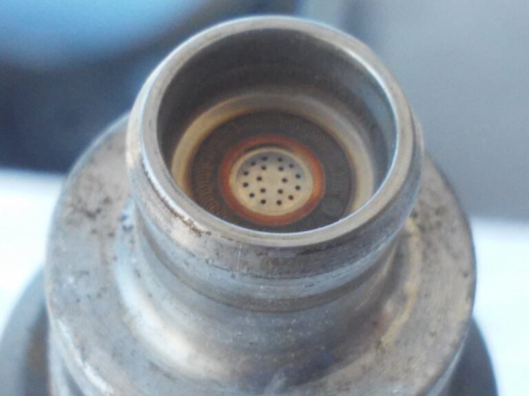
I noticed the 5th gen injectors are 4 hole, and the 5.5 gen are 18 hole. The flow rates are slightly different 306cm/min – 5th gen 294cm/min – 5.5 gen. Besides that, they looked identical.
The article talks about how more holes help atomization. So my thought was, why not try some 18 hole injectors in my 5th gen LIM and see if it helps.
Here is a pic of the 5.5 gen injectors (missing the pintle cap. Many of the caps were stuck in the LIM. I had to pry them out and pop them back on.
First a little back story on my 00VI swap:
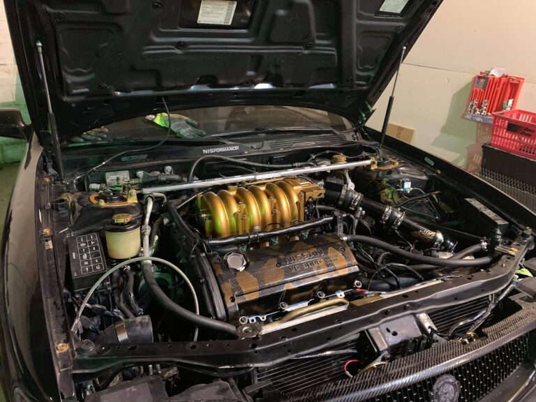
August of last year I completed the 00VI swap with the 4th gen LIM and IACV. 5th gen TB, UIM (obviously), and EGR delete.
June of this year I swapped the the 4th gen LIM with the 5th gen LIM. (I had no way to tune at the time of my initial 00VI. I added a Emanage Blue in the spring) I felt a little bit of improvement over the 4th gen LIM. Not a big boost, but every little bit helps. Tuning is not my strong spot, so I’m running on a basic street tune. I’ll work on getting the map fine tuned when I get around to it. WOT runs 10-12 AFR.
I took a quick trip to the junkyard and picked up 6 5.5 gen injectors. They fit right in, no issues at all with the install, even the plugs are the same. It was more of a pain to take the UIM off for the third time in a year. I cleaned them first, just as I did with the 5th gen 4 hole injectors.
I didn’t touch the tune, I figured the difference was small enough I could take on the task of tuning later.
My first impression is WOW. These new injectors are great!!! I can’t believe I haven’t heard about this on the .org
Mid throttle low RPM made the most improvement. Not a lot of gain at high RPM, but no losses. The best gains are below 3500 rpm at mid throttle. Idle seems a little smoother to boot. This is a great mod, especially if you are doing an 00VI with the 5th gen LIM. I can’t get over how much more power I have below 3000rpms. Without touching the tune from the 5th gen injectors, I’m running 12-12.7 at WOT. SO that problem seemed to take care of itself.
It’s too early to tell, but I’m hoping my gas mileage might go up slightly also. You know the spot your used to resting your foot to keep a certain speed (25mph, 55mph, etc.) I had to re-learn my position, I found myself slowly accelerating with my current foot position.
This is a working ECU for a 1995-1998 4thgen Nissan Maxima. This ECU is tuned for 560CC injectors and Z32 MAF. It can be adjusted properly updated from JWT to any mods you have. This upgrade was $595 got this ECU from mitesh patel years ago with another tuned software.
You really need an OBD II code reader/eraser to tackle this problem. I got mine a few years ago from Autozone for like $120, and I can’t even tell you how valuable it has been.
THIS IS HOW I PASSED MY SMOG CHECK – vs. a never-ending code 1320!
You will need:
OBD tool
Printout of System Readiness Drive Pattern for your model (yes it is silly)
Access to a freeway that is not too busy (you will be traveling slower than normal traffic and trying to hold maintained speeds)
You should also try and do this starting with a little less than 1/2 tank of fuel.
** I’ve found that the best freeway system to do this will have 6-8 continuous miles of flat or upwards sloping hills, followed by a downslope. In or around Los Angeles, you can get on the 5 south at Magic Mountain and by the time you reach the top of the hill, it’s the perfect time to downshift and coast.**
Abbreviated Systems reset procedure. (At least for my car!)
Get your car close to your freeway on-ramp. (make sure it is warmed-up)
Reset CEL
Start car and let idle for 1.5 minutes – leave A/C off for now
Get on the freeway, get up to 4th gear and try and hold the RPMs just over 3000 (3100 should be fine) you should be traveling around 60-63 MPH. HOLD THIS STEADY FOR 3 MINUTES>
Shift into 5th, steady speed around 56 MPH, turn A/C on, set cruise control, HOLD FOR 3 MINUTES.
At this point, you should be getting close to the top of the hill, wait until you crest the top, then…
Downshift into 4th, take your foot off the gas and just let it go for 5-6 seconds, then drop out of gear and let it coast for 1 minute without braking for as long as possible.
At this point, 4 of my 5 systems that need to come back online had reset. (I’ve successfully done this on 3 separate occasions.) If you leave your OBD tool hooked up while driving you can check the status by looking at the I/M Indicators. The 5 that we’re looking for are O2 Heater, EGR, Catalyst, O2 Sensor, and EVAP.
Get off the freeway and go to the first smog check place you can find. (probably helpful if you plan that out beforehand)
In California, my understanding is that you can take the smog test with a maximum of 2 system readiness indicators not ready, but no more than that.
So the plan here is to get at least 3 of your 5 SR indicators back online, then get the smog check before the CEL comes back on. You don’t have much of a window to do this, and I would recommend limiting turning off and restarting the car as much as possible. I’ve even let it idle in the front of the Smog place while I went and checked in.
Out of the 3 times, I have done this the CEL has always come back within 10 miles of leaving the Smog Check, 2 years ago, it came on as I was pulling out of the lot. Luckily, I had just passed my test. But I have always had a small window to get it done before the light comes back. It’s actually pretty nerve-wracking sitting in the smog check place praying the damn light doesn’t go on during the test. But if you pass, it’s completely worth it. I feel like framing my last pass certificate.
When the steering wheel is turned quite a bit (like in a parking lot) you hear a crunk-crunk-crunk.
The upper strut bearing grease dries out which makes the bearing stiffer and more difficult to turn. When this happens, as you turn the steering wheel the bearing does not move, but the front spring “winds up” until there is enough force to overcome the stiff bearing. Then you hear the crunk as the spring unwinds. The whole process repeats over as you turn the steering wheel.
Solution:
Remove the upper strut bearing, and REPLACE them ($25 each) with new ones. Repacking the grease is tricky, if you don’t pick the correct grease, you will have the problem return in 8-12 months. (I did)
Remove the 2 large nuts and bolts that join the strut, to the steering knuckle.
Not shown: Remove three nuts from the top of the strut. Remove the clip that holds the hydraulic brake line, and free brake line from strut. Remove the 10mm bolt that hold the ABS sensor cable to
the strut.
Attach the spring compressor. Tighten the spring compressor finger tight.
Place the strut in a vice. (carefully, don’t clamp down too much) Tighten the spring compressor until the spring is just a little loose. Remove the single strut nut. This is very easy if you have air tools, but if you do not, then you will need to hold the shaft, and remove the nut.
Be very careful here, springs can KILL and have killed. Always stand beside the spring with the ends pointing to your left and right. If it does break free, it will only put a hole in your wall, and not you.
Remove the dark orange noise insulator, remove the black rubber insulator
Remove the lower part of the black rubber insulator.
The clean spot you see in the center is the place where the strut bearing sits. (Notice all the sand in the upper spring perch. Two out of three drainage holes were blocked with road sand from 5 years of Canadian winters. Make sure to clean out any debris, to allow proper water drainage.
Believe it or not, this dark colored tiny PLASTIC piece is the strut bearing.
The upper strut bearing
The inside of the upper strut bearing.
UPDATE:
Do not try to re-grease the bearings. I did, and it lasted 10 months, and the same noise came back. Spend the $40, and it is fixed for the life of the car.
Above: This is a close up of the dark coloured bearing end cups, and the white ring.
To assemble, just reverse the steps. Make sure you tighten all nuts and bolts to the factory specification which are found in the Nissan Service Manual. Since your entire front suspension has been removed, you must get your alignment done, if you want your tires to last.
Summary:
With the new strut bearings, it turns smoothly, and the crunk-crunk-crunk sound is gone because the spring on the strut will not be “winding up”.
Total cost was $40 for the new upper strut bearings. My alignment was a little more at $80, but now my front camber, and toe are in spec.
When I would tell my friends that I had replaced my brake pads and brake shoes they were shocked. They would ask me “Why would you do that?”, “Do you know what you are doing?”. Some would tell me “I would never do that, what if you did something wrong? You should not touch with your brakes. Leave them for a mechanic” However, as you will soon see, changing your front brake pads are really quite simple. I will show a step by step pictorial, from when I changed my front brake pads and rotors on my 95 Maxima.
Raise the front wheels, support with jack stands, and remove the front wheel. Always work safe, and use proper jack stands that are in excellent working order. You life may depend on it.
Here is a close up of the caliper and rotor.
If you look in the “inspection window” of the caliper you can see how thick your pads are. Here you can only see the inner (shown on left side of photo), as the outer pad is hidden in the shadow.
This is a close up of the upper part of the caliper. Here you can clearly see the inner (left) pad, rotor, and the outer (right) pad. Notice the outer pad is quite thin, compared to the inner pad? More on this later.
Remove the 14mm bolt from the top of the caliper.
Remove the 14mm bolt from the bottom of the caliper.
Remove the caliper. It should slide off, with little force. Using a some wire, hang up the caliper from the spring perch, checking that the caliper is not hanging by the rubber brake hose. Right:
Here is the view of the caliper piston and piston seal.
The brake pads, shims, and upper and lower are shown here.
Remove the brake pads by sliding them out, with the shims. Then remove the thin metal clips that are on the top and bottom of the caliper. They are there to enable the brake pads to easily slide on them, and they also have clips that holds the pad, so they don’t rattle over bumps. The shims, and the clips are part of a “brake hardware kit” Nissan recommends that they are replaced when the pads are replaced, but I replace mine only when the the shims show moderate corrosion. (We use A LOT of salt in Canada during the winter)
With the brake pads, and upper/lower clips removed. NOTE: You can see the caliper resting on the rotor. This is an example of what not to do. If the caliper slips and falls, the brake hose will stop it from falling, but the hose will be strained, and it may leak. To prevent this, hang it up with some small wire from the front spring. Right:
Remove the two 17mm bolts that hold the “torque member” (hey, that is what Nissan calls it) Remove the torque member.
The rotor should slide right off the hub. If not use a 2×4 to tap it, until it is unstuck from the hub. Right:
With the rotor removed, you can see the hub. NOTE: the silver stuff on the hub is anti-seize compound. This should prevent the rotor from rusting to the hub.
Summary
At this point the brake pads, torque member, and rotor have been removed. It is now time to clean up the brake hardware, remove the old grease and re-grease the caliper locating pins. Click Front Brake Reconditioning, to continue.
So far, we have removed the front brake pads, shims, caliper, torque member, and rotor. It is now time to clean up the brake components, clips, shims, and re-grease the caliper sliding pins.
Scrape any loose rust of the area shown above. You want to make sure that clips fit all the way to the bottom. If not, your brake pads may get “hung up” on the clips, and this could lead to your brake pads dragging just a little bit, causing them to wear unevenly.
This is the brush that I like to use. It has stainless steel bristles and it removes any rust very fast. I purchased it at Princess Auto, for about $6.
To remove the pin that the caliper slides on as the brake pads wear, you can gently pull them out. If these stick in any way, the caliper will not be able to slide to (brakes on) are away (brakes off) from the from the rotor. This can lead to the brake pad dragging, and this causes the pad to wear very rapidly. In one case I saw a car with the rotor glowing red!
On the top of the picture is the upper pin (as located on the torque member), the other pin is the lower pin. You can see that the grease here is in fair condition.
Use the small wire brush to clean around the torque member where the brake pad clips, and rubber caliper pin boots are. Clean out all the old grease from where the caliper pin slides in the torque member. Right:
I turn the caliper pin boots inside out to remove all of the old grease. The grease shown here is not in very good shape.
Before (right) and after (left) pictures of the clips during cleaning.
A close up of the freshly cleaned pad clip.
Place a small amount of grease (high temperature synthetic) on the pin, and in the hole. Push in the pin all the way to expel excess grease. When you pull the pin out, if it is a little stuck, then you have too much grease. Pull out the pin, and wipe off some grease and try again. If you have too much grease, air can not get in behind the pin as you try to pull it out and it is a little “hydro locked” You want these pins to slide very easy.
Place a little grease (again, high temperature synthetic) in the boot, place the boot over the pin, and put the pin in the torque member. Push the pin in all the way, and lift the boot so that any trapped air, or excessive grease can escape. Check again to make sure the pins slide easy.
Brake pad shim, with a little corrosion.
Close up of the corrosion. The next time I will purchase the brake hardware kit, and replace the shims. I don’t want anything that can compress slightly under hard braking between my caliper, and my brake pads. (like corrosion)
Summary
At this point the brake pads, torque member, and rotor have been removed. The caliper sliding pins have been re-greased, the torque member clip attachment area has been scraped and cleaned, as well as the brake hardware (shims & clips) have been cleaned. The caliper pins, rubber boots, and the torque member items have all been assembled. Click on Front Brake Assembly to continue.
Front Brakes – Assembly Update So far, we have removed the front brake pads, shims, caliper, torque member, and rotor. We have also cleaned up the brake components, clips, shims, and re-grease the caliper sliding pins.
Now it is time to assemble.
You MUST remove the protective coating that are on the new rotors. It is like a thin coating of thick grease. I like to use isopropanol alcohol as it cuts the grease quickly, and dries without any residue. Keep turning the rag until it wipes clean. Do not use gasoline as a cleaner, it is just too flammable.
Place the cleaned rotor on the hub. I put a little dab anti-seize on the outside edge of the hub. This is to ensure that I won’t have any problems getting the rotor off down the road. Notice the caliper is resting on the rotor’s dust shield. It really should be hanging up to ensure the brake hose does not get tugged, and develop a leak. Do as I say, not as I do 😉
I like to use a little anti-seize compound to make disassembly easier down the road. These are the 17mm bolts that hold the torque member.
Bolt on the torque member, attach the pad clips. Note: The single wheel lug is to hold the rotor flat against the hub.
Slide in the brake pads. Make sure your hands are free of grease and oil.
Put on the pad shims
Open the cap to your master cylinder to let the air out, as we push back the caliper piston. You should not remove it, just untwist it. Brake fluid likes to absorb moisture, and this can cause corrosion and a lower boiling point of the brake fluid. Right:
Carefully and very slowly push the piston back. Notice that the C-clamp is strait. If the clamp is crooked, you may cock the piston in the caliper. It does not take a lot of pressure to push it back. If you need a lot of force to push it back, your piston may be cocked sideways, or partly seized.
The piston is fully pushed in.
You can see how much the brake fluid level rises for just one side. Never let anyone at a “Rapid Lube” type place “top up” your brake fluid. It will just overflow the master cylinder when the next brake job is done.
Slide on the caliper, and tighten the bolts
Make sure the caliper pins are positioned as shown. The pins have a flat spot, and the casting of the caliper has a “bump”. Make the pin is sitting flat, and not on the raised part of the caliper.
Remove the wheel lug, and bolt on the tires. Time for a test drive.
Here is why I had to do my brakes. The outboard pad on the driver’s side was worn down to the “noise maker” I think this was due to too much grease (and not enough air) in the caliper pins, which would hold the pad against the rotor just a little. Over time it wore the pad down. All other pads wore the same. My fault, but you get to learn from my mistakes.
Here is what happens to your rotor when you use them a lot. You are looking at thermal stress cracks on my old rotors. This is caused by the rapid increase in temperature under hard braking. Over time the disk can fracture. I was not going to wait for that, so I spent $65 per rotor at Canadian Tire. (Nissan rotors are $90)
After 255,000 KM I decided to replace my alternator. It was not because it was not working, it was because of a bad bearing and the awful low RPM knocking noise it made that had become louder and louder in the past 18 months.
I was 100% certain it was the alternator. I did this simple test:
Get a long flat blade screw driver eight to ten inches long
Hold the metal part on the end of the alternator (CAUTION: do not jam anything in the alternator!)
Place your ear on the handle of the screw driver
Listen
I heard a very loud knocking sound. Then I placed the screw driver on the compressor for the air conditioning, the idler pulley and they were almost silent.
I called the local Nissan dealer to get a price on a rebuilt alternator. It was $440. (or $387 with a 15% discount) Then I remember an article I read in the Toronto Star about a local place that rebuilds alternators and starters. I called Start Auto Electric and was quoted $260. In both cases they want the old alternator back, so they can rebuild it. Fine with me, I won’t need it.
The rebuilt alternator from Start Auto.
Disconnect the battery. (and clean up the battery connections!)
Loosen the belt pensioner about 810 revolutions (shown by yellow arrow)
Remove the lower right plastic cover from under the car.
Loosen the nut on the idler pulley. (shown by yellow arrow) Push up on pulley, and snug the idler nut. This will give you some slack in the belt to make it easier to remove. Right:
Remove the drive belt by pulling it off the idler pulley.
Remove the air intake snorkel. (if you still have it)
Disconnect one electrical plug for each fan. (yellow and green arrows) You will also have to remove 2 clips from the fan shroud that hold the wiring harness going to the fan on the left.
Remove the two fan shroud screws. (shown by the yellow arrows)
Remove the hose clip, and disconnect the overflow tube from the radiator filler neck, and the fan shrould.
Lift out the fan shroud. Be very careful, the radiator fins are very easily damaged.
The fan shroud. Notice that each fan has a different number of fan blades.
Disconnect the 2 wire plug. On my car the release clip was stuck. I used a small screwdriver to disengage the clip, so the plug can be easily removed. Right:
Loosen the top alternator bolt, but do not remove. We don’t want the alternator to fall. Not shown: Remove the lower alternator bolt and nut. It is located directly opposite to the smaller bolt on the top of the alternator.
Remove four bolts that hold the air conditioning compressor.
Remove the top alternator bolt. It will now rest on the compressor which is sitting in a bracket.
Gently push the compressor toward the back of the engine. This will give you just enough space to remove the alternator as shown. This is very tricky, and it may take quite a while to get the compressor in just the right position so that you have enough space to get the alternator out. Right:
The yellow arrows show the two mounting points for the alternator.
After much “trial and error” the new alternator is in position. Tighten the lower bolt and nut. Tighten the upper bolt. Connect the large cable, and tighten the nut. Push in the 2 wire plug.
Tighten the 4 bolts on the air conditioning compressor.
Install the drive belt, making sure it is properly seated in the middle of all pulleys.
Install the fan shroud, the end caps, connect the two plugs for the fans and connect the overflow tube.
Tension checking points Right:
Tighten the drive belt tensioner (yellow arrow) until the belt deflects 4.2 – 4.6 mm (used belt) or 3.8 – 4.1 mm (new belt) at the “Tension checking points” while pushing in with 22 pounds of force. (I know this seems like a difficult way, but this is from the Nissan factory manual. I think most people guess. I tighten the belts until they just stop squeaking)
With the drive belt at the correct tension, tighten the nut on the idler pulley.
Install the air intake snorkel, and the lower right plastic cover.
Summary
This is not a hard job, but it can be very time consuming. You will need some patience, some good luck, and a little skill to change the alternator on a Maxima.
I have found that I need to clean my throttle body about every 30,000 KM. If I don’t my idle will sometimes fall to below 500 RPM, and the motor catches itself and revs up to 1,000 RPM to then fall back to about 750 RPM. If it is very dirty it stalls. I also noticed my 1st gear launches become very jerky.
You may also notice a loss in lower RPM torque. If the throttle body is very dirty, the idle speed control valve (ISC) can not allow additional air to bypass the butterfly plate in the throttle body. The is the reason for the jumpy idle noted above, as well as a loss in low RPM (1,000 to 3,000 RPM) torque. The ISC has a strong influence on the air/fuel mixture up until about 3,500 RPM.
When you clean the throttle body and butterfly plate, you allow the ISC to do its job. This is not very hard to do, with the cost being about $8 for a tin of “Combustion Chamber Cleaner”
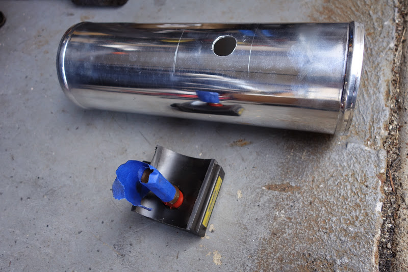
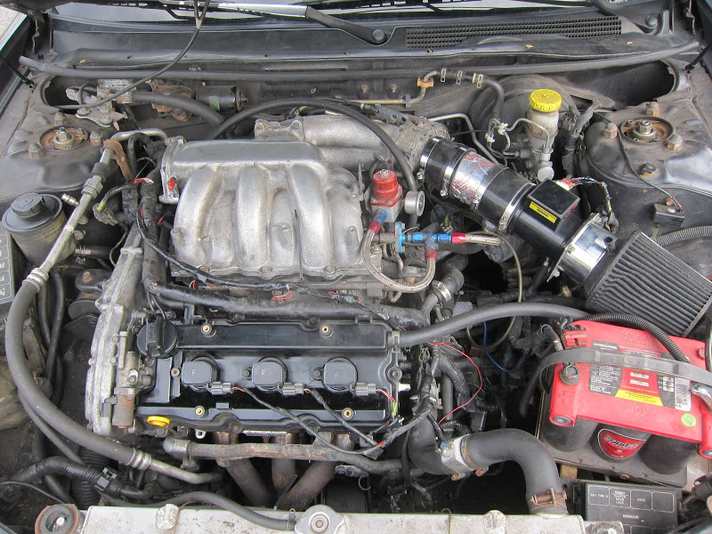
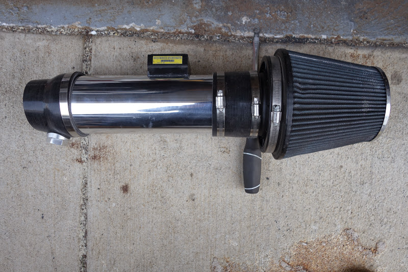
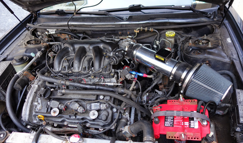
Ihave a Stillen Cone filter from my NX-2000. I was able to drill and tap 3 more holes to reuse it. It fits perfect. Anyways, disconnect the ACT (air charge temperature) sensor shown by white arrow.
Remove the air filter, and disconnect the MAF (mass air flow) sensor.
Remove the clamp as indicated by the white arrow. As shown in the picture, slide it up hose so you don’t forget about it or loose it. Right:
Remove the small black rubber hose as shown by the white arrow. The yellow arrow points the to disconnected rubber hose.
Remove the clamp as indicated by the white arrow, and slide it to where the yellow arrow is for safe keeping. Right:
Loosen the worm gear clamp on the throttle body.
Remove the bolt as shown by the white arrow. Right:
It may take a little work, but now you can remove the oil separator / MAF as one unit.
Now you can see that we have very good access to the throttle body. Right:
Here is a view inside the MAF. The smaller circle in the middle hold the “hot wire” to determine actual air flow.
We have removed the air filter, MAF, and the oil separator. (the big black box) We now have easy access to the throttle body and butterfly plate. Time to clean!
The gray arrow shows the build up of dirt and oil. (No, it is not a shadow) Right:
Here is what I use. It is available at Canadian Tire.
With the throttle wide open, spray the cleaner in, and wipe with a clean white rag. Make sure to remove any dirt and oil from the EDGE of the butterfly plate. The white rag allows you to see how much dirt and oil you have removed, and when the throttle body wipes clean, and the rag stays white, you are done. Right:
I like to use an old tooth brush to clean the throttle body. I hold the throttle wide open, spray in the cleaner, and scrub the throttle body with my tooth brush. (as seen resting on the throttle body) You won’t believe the dirt and oil in there!
Here is the clean throttle body and butterfly plate. Right:
This is the dirt and oil removed. This rag was new.
From here, just follow the opposite if disassembly. Make sure not to over tighten anything. A common belief is that it is better to have it a little too tight, than too loose. From what I have seen, when bolts (especially small 10 mm bolts) are over tightened they strech and are very difficult to remove the next time. My rule of thumb is snug plus 1/4 turn for the small bolts.
Summary
When the car is put back together again, you should notice your idle being more stable, and maybe improved low RPM torque. I know I did, but my throttle body was quite dirty.