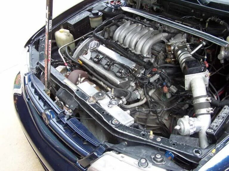
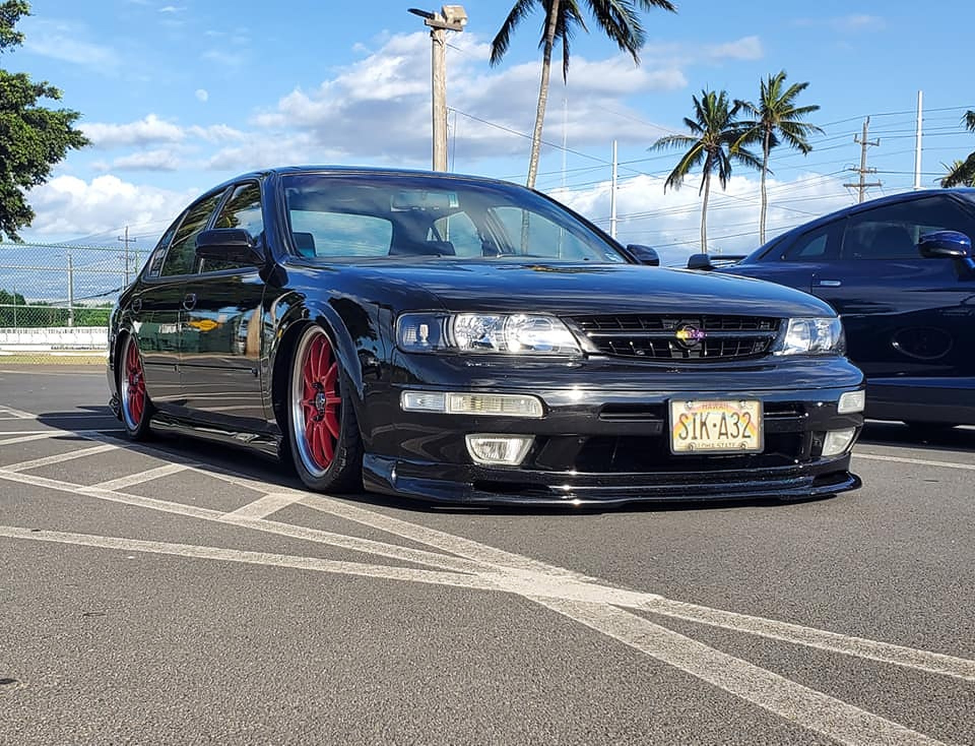
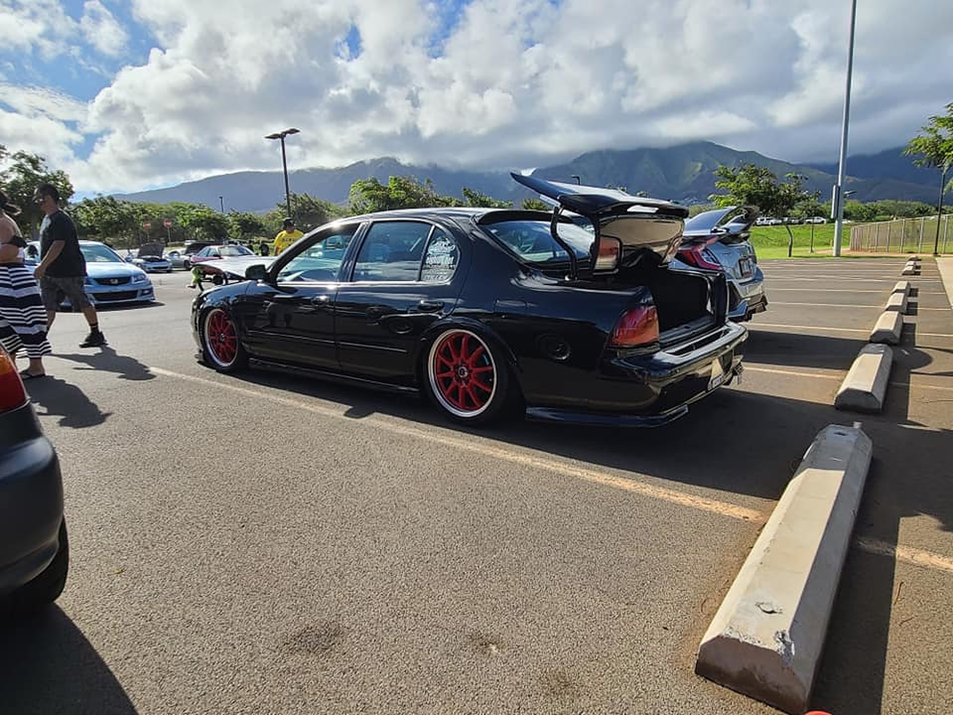
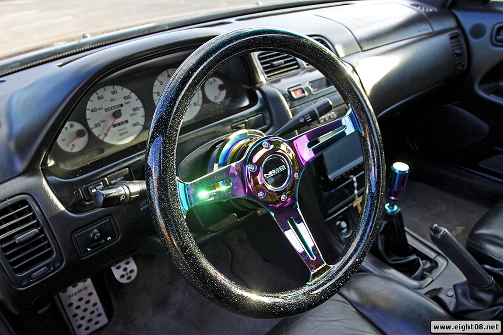
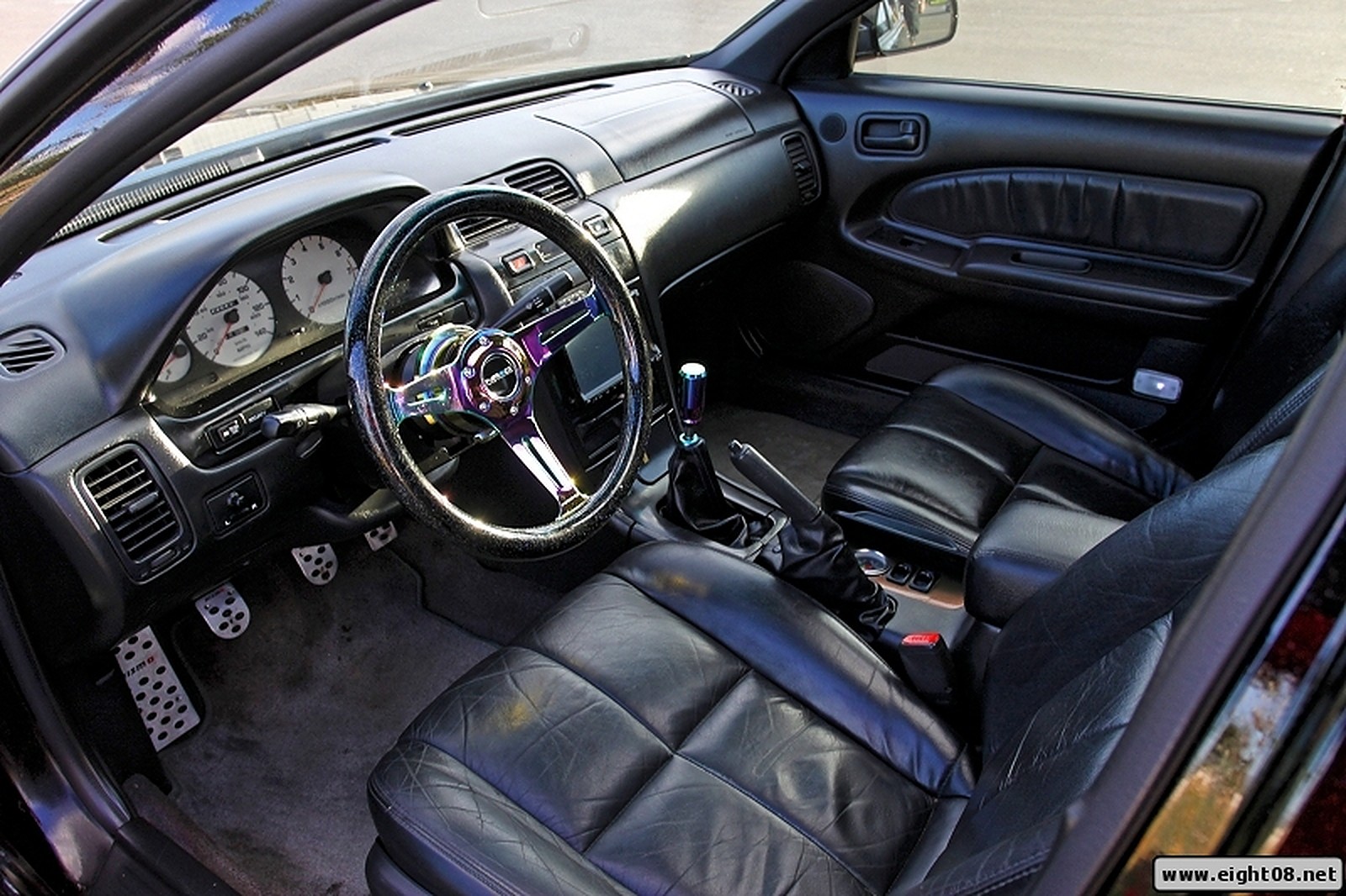
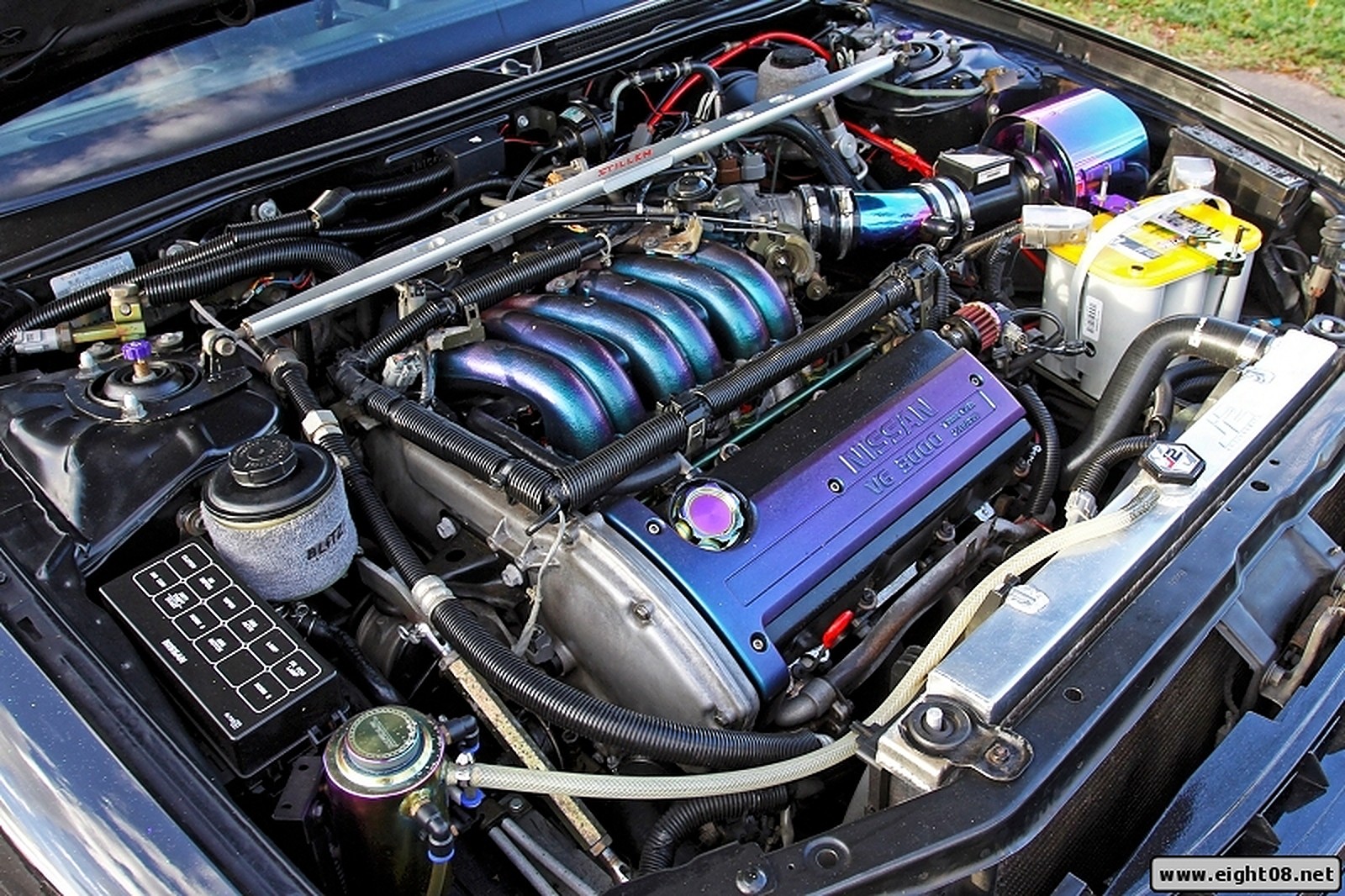
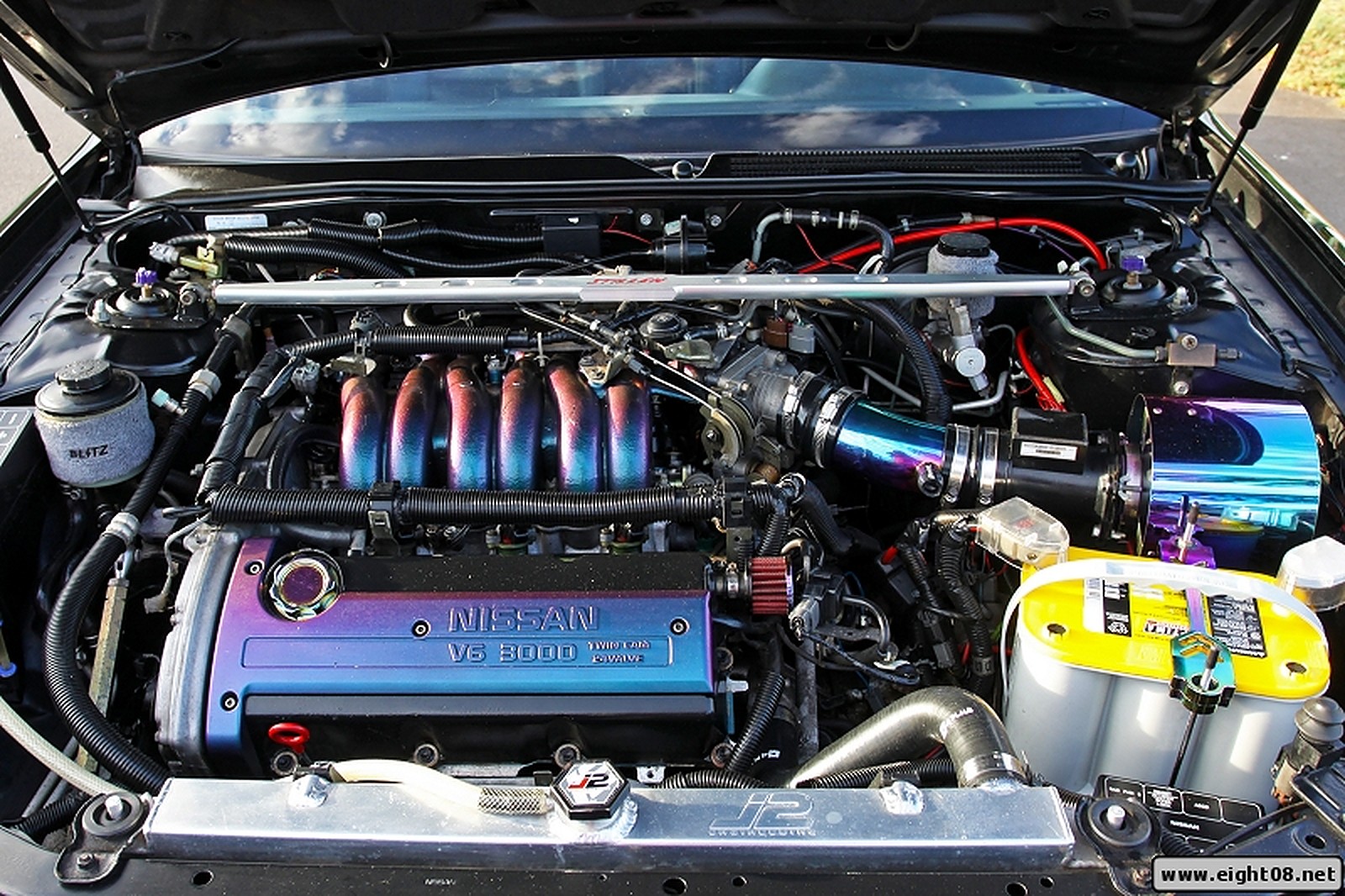
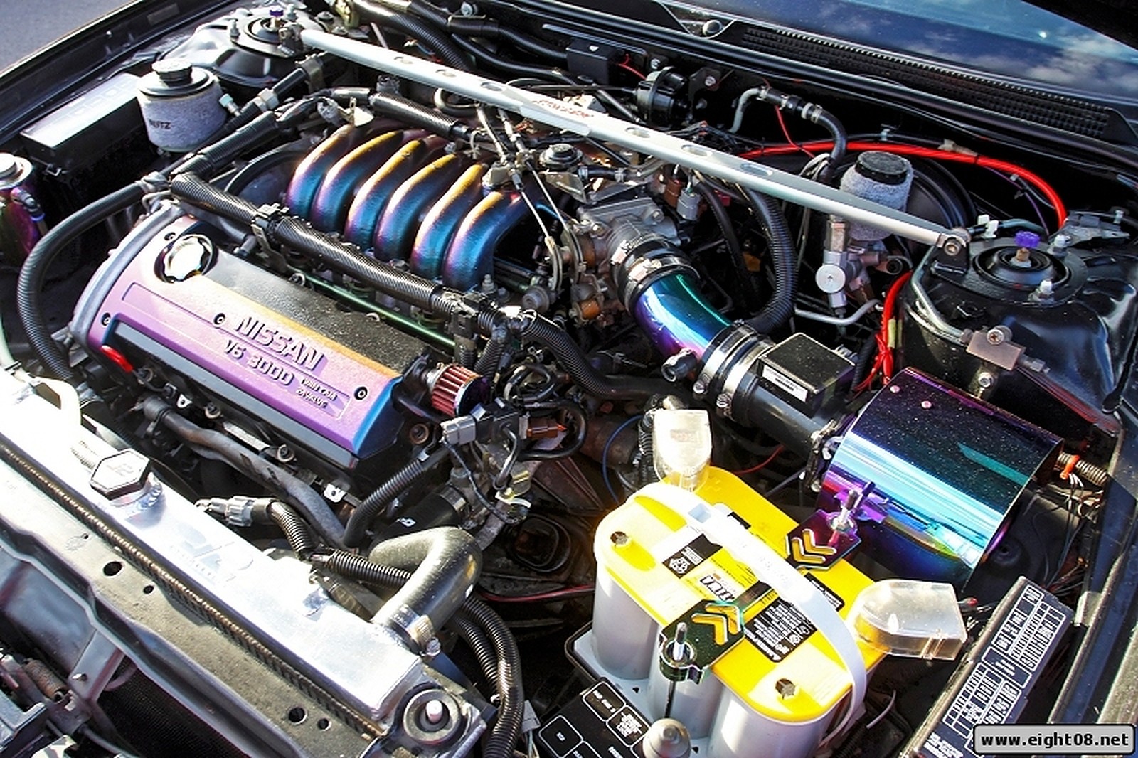
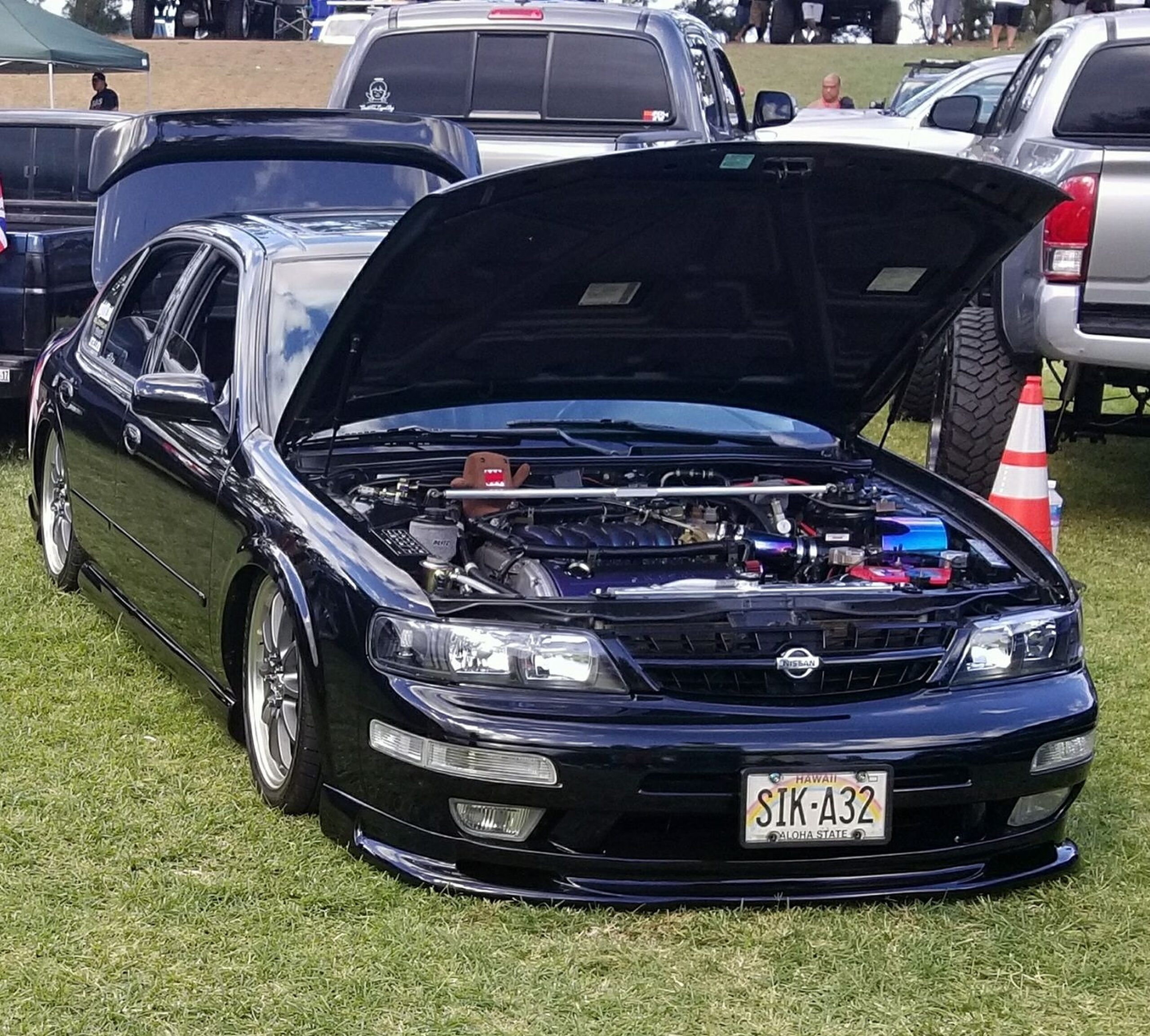
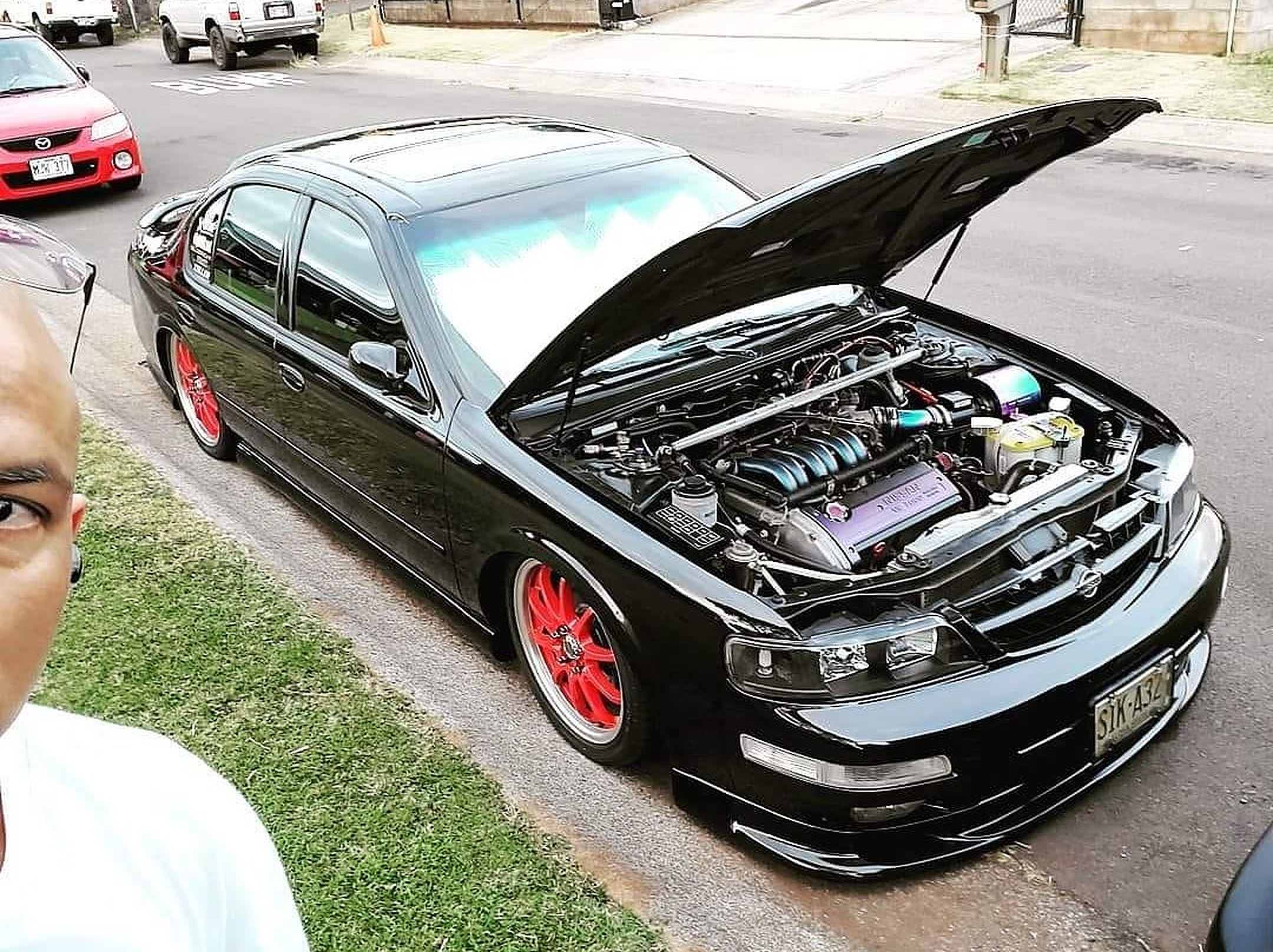
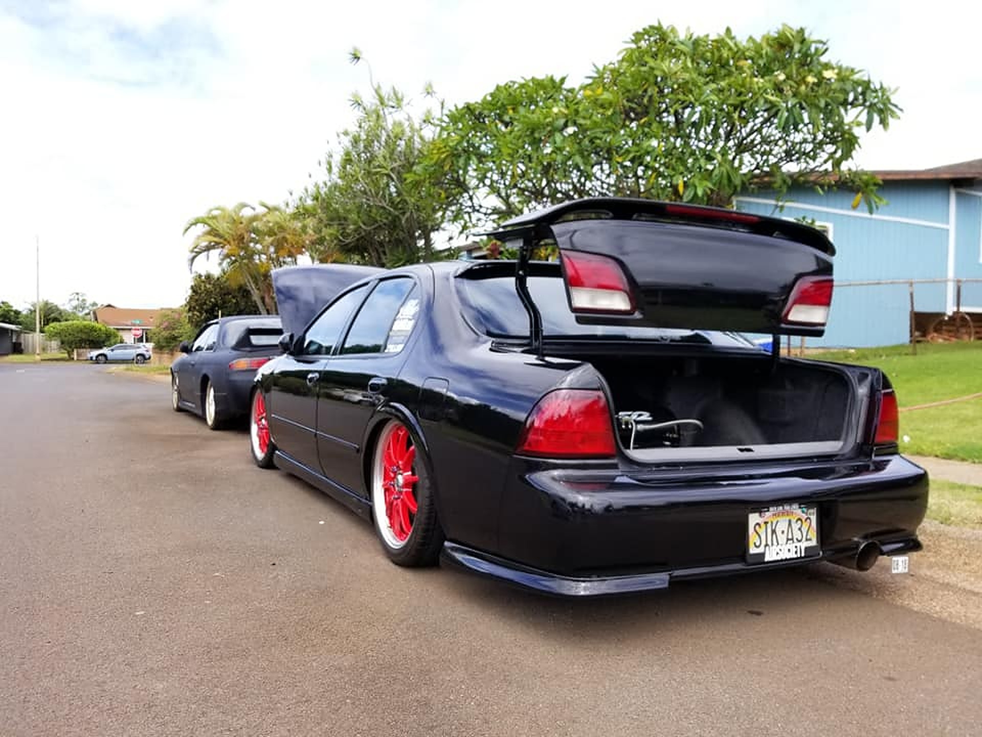
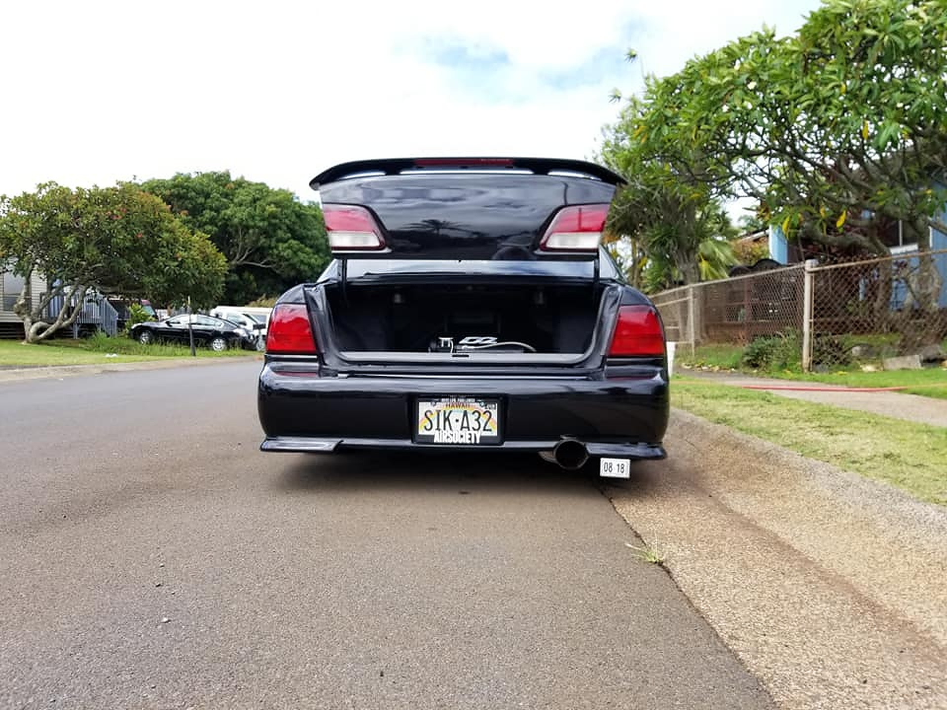
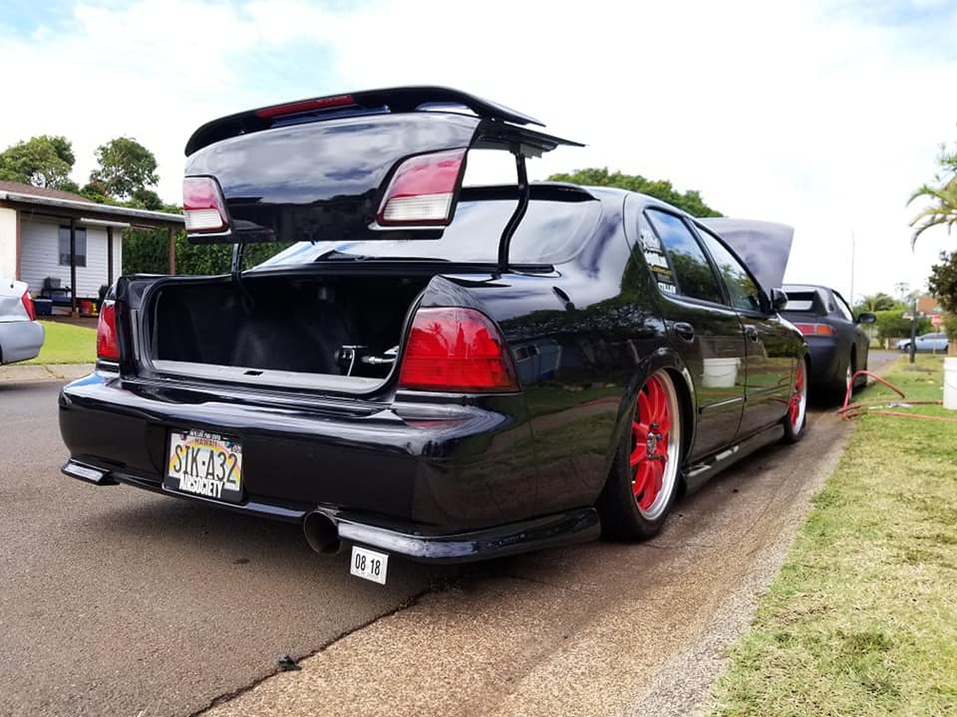
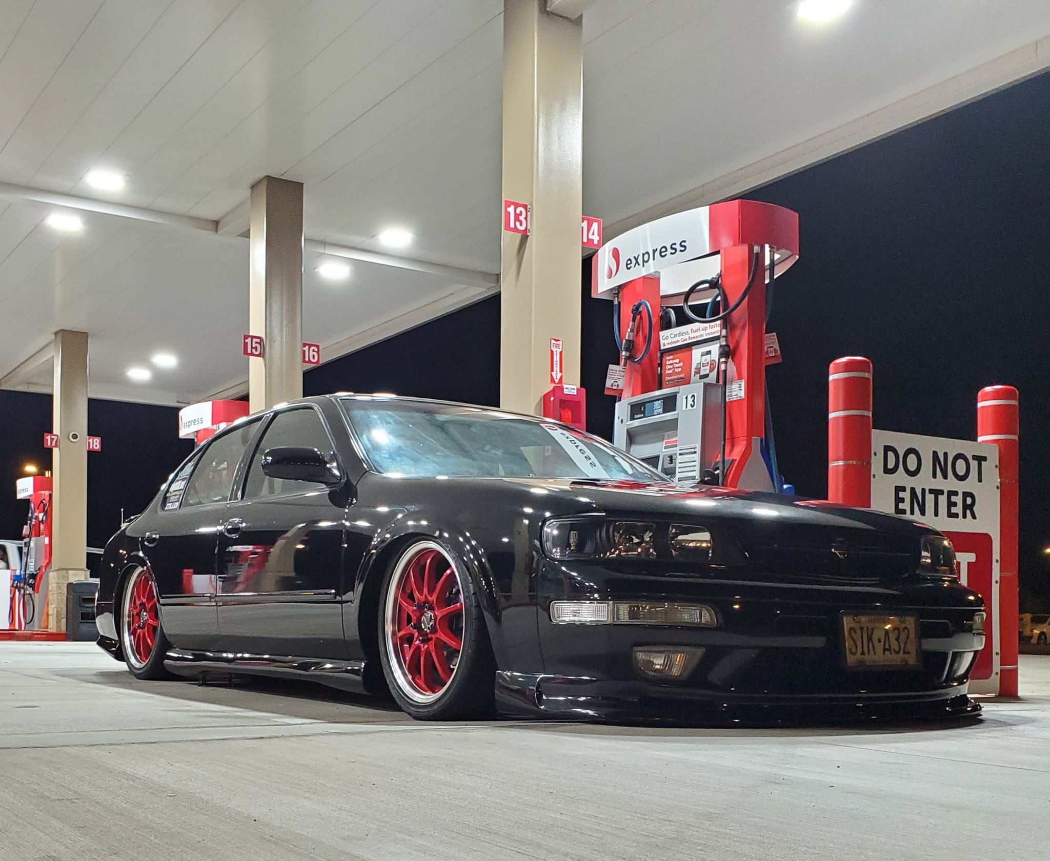
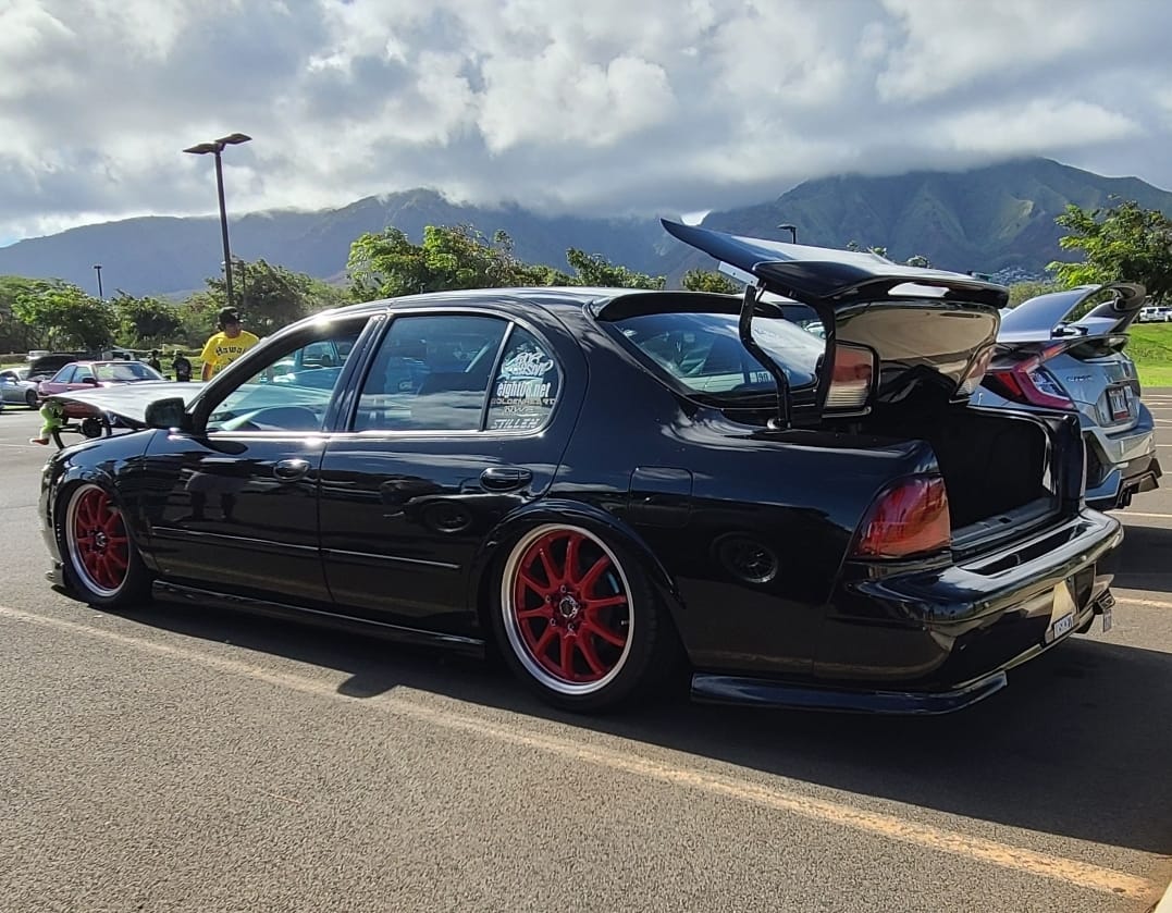
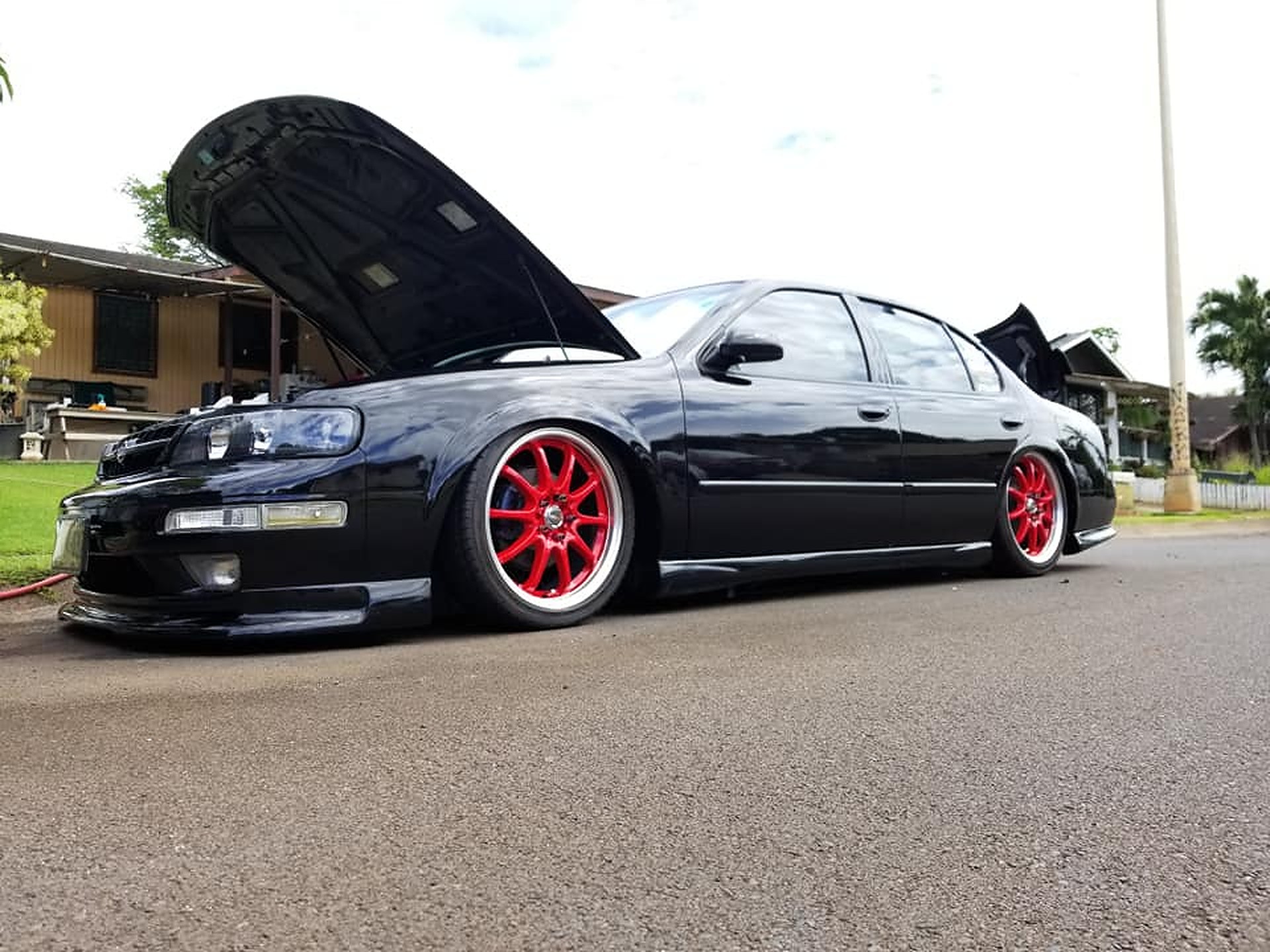
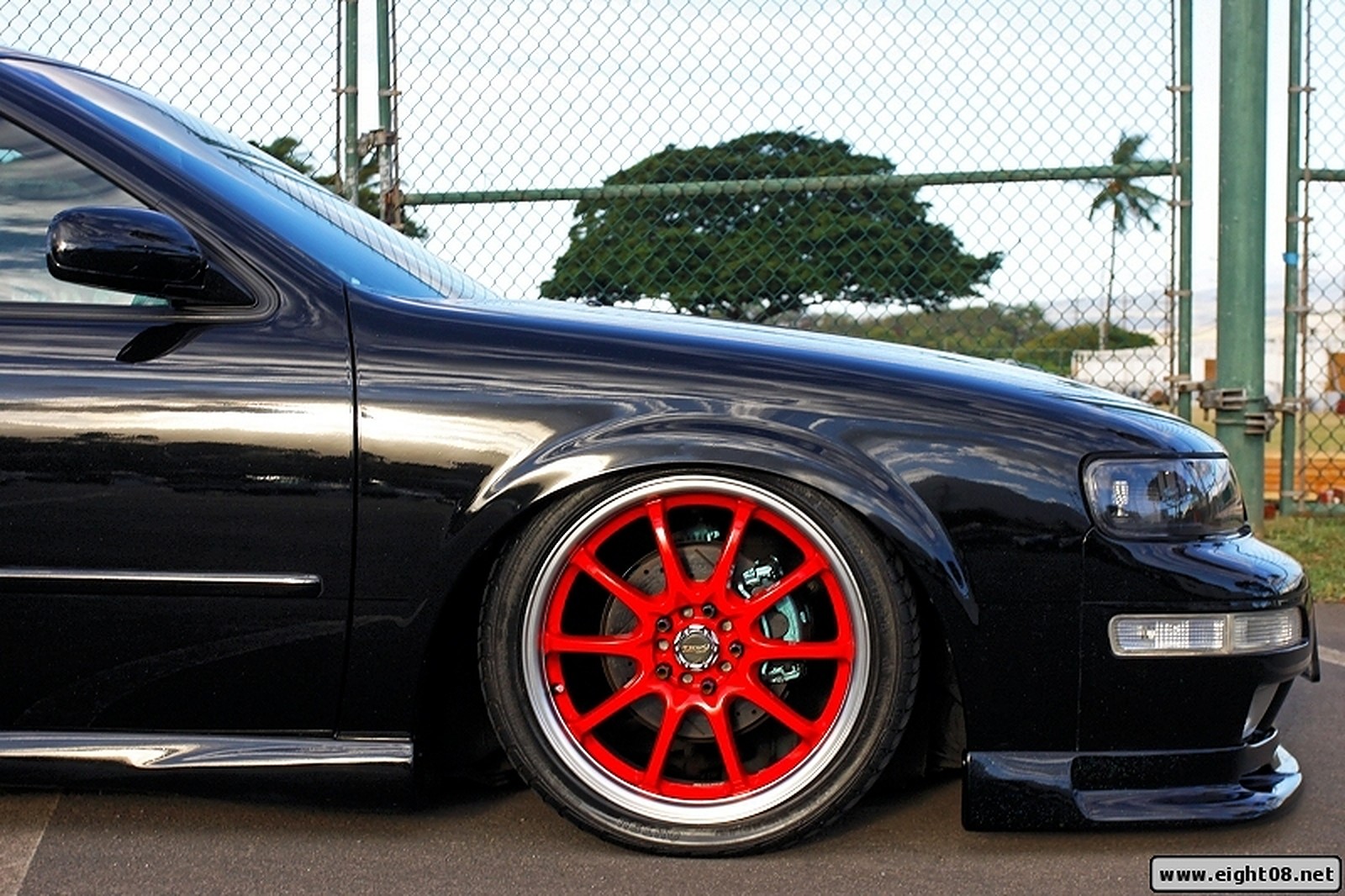
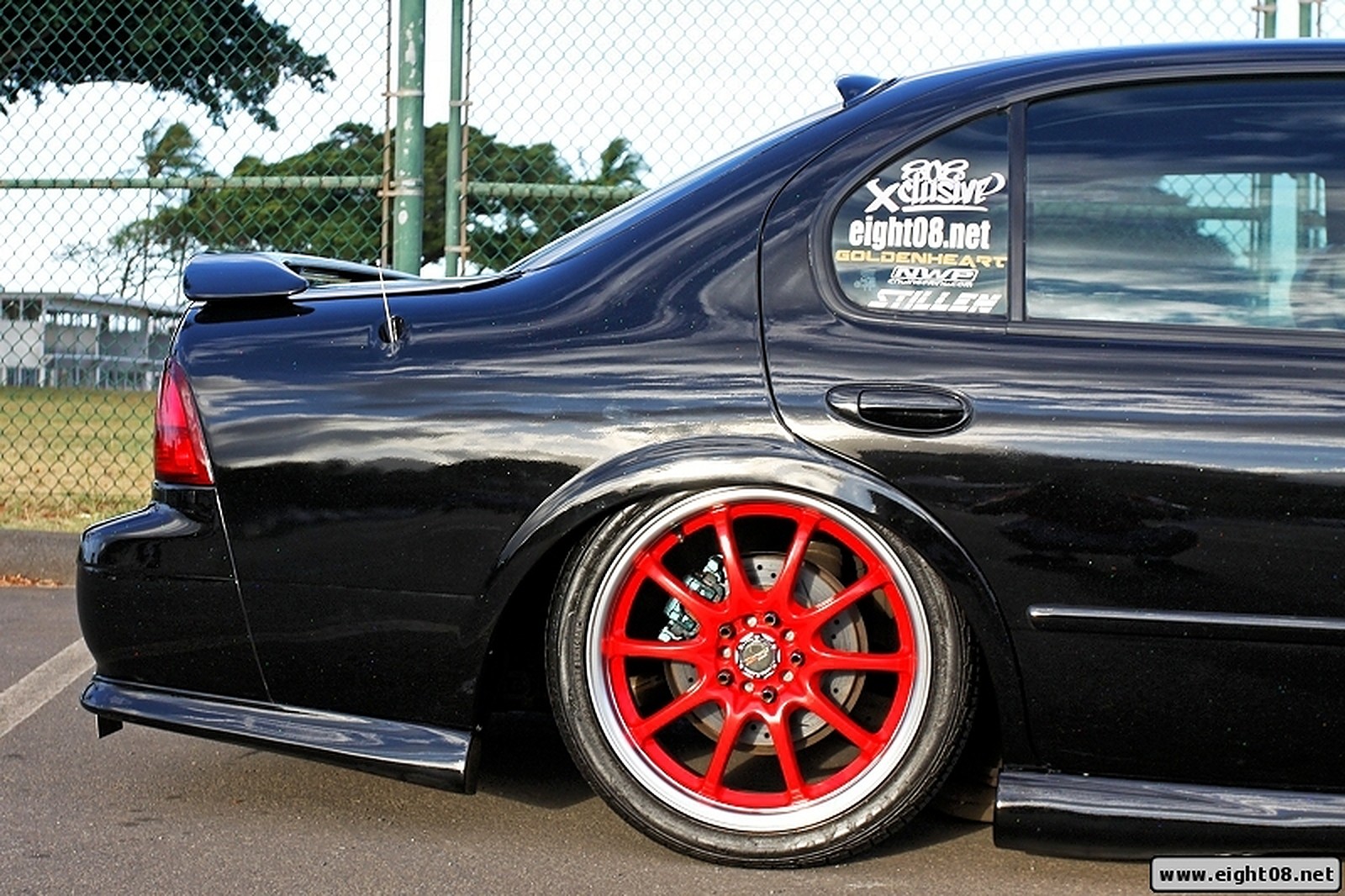
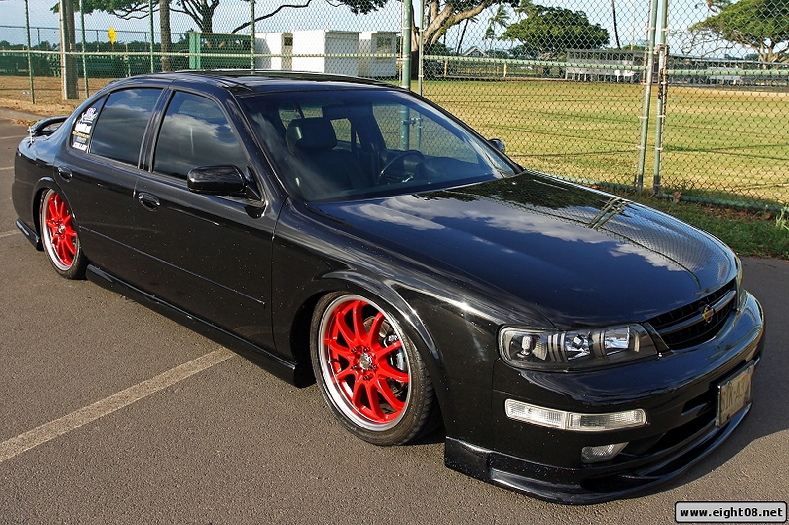
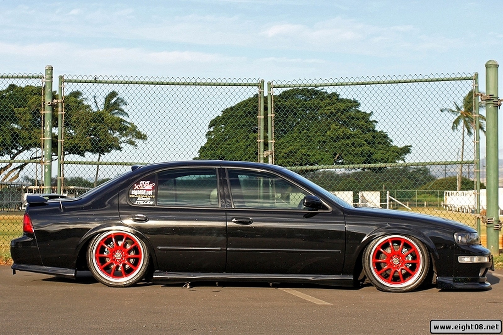
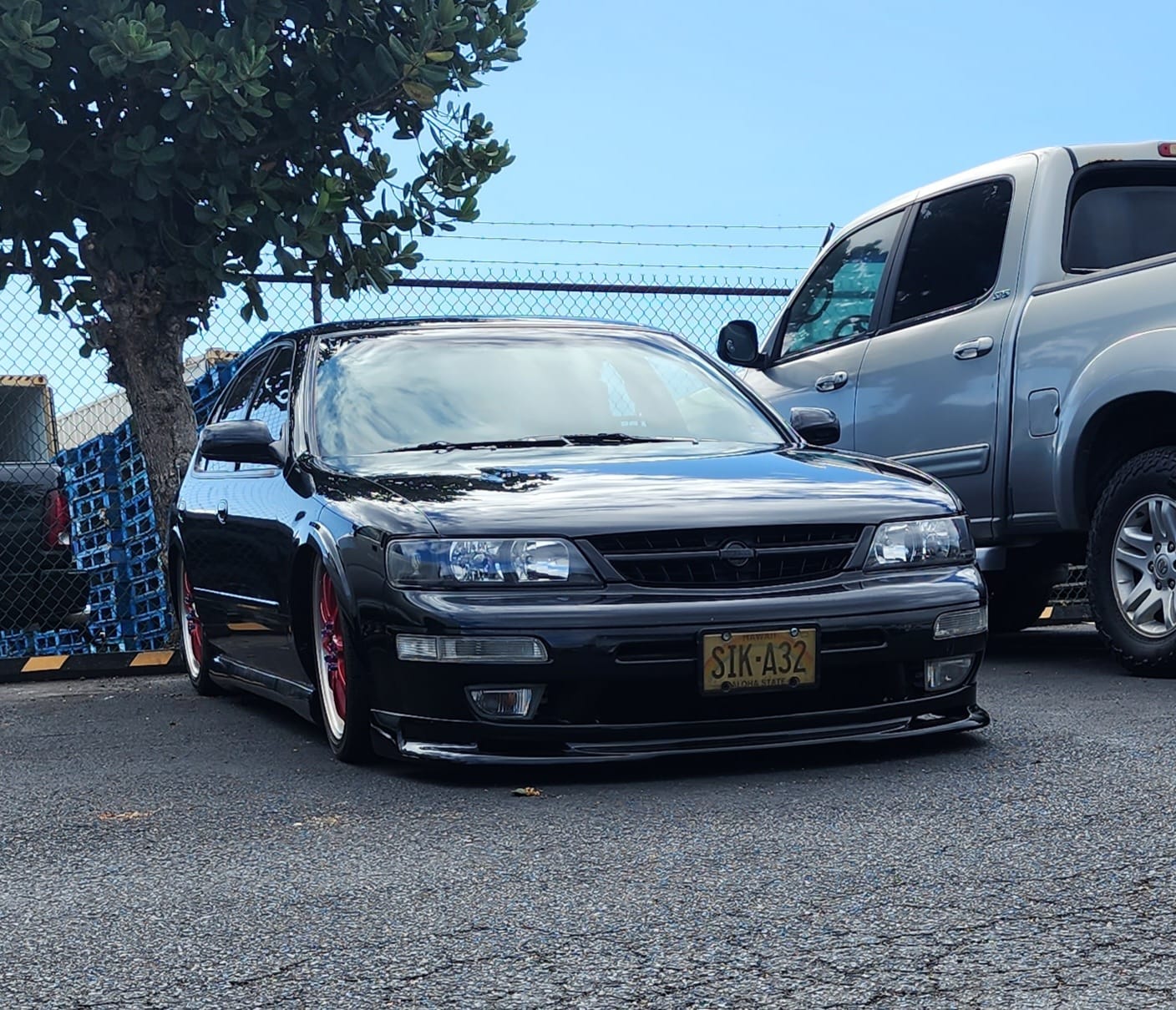
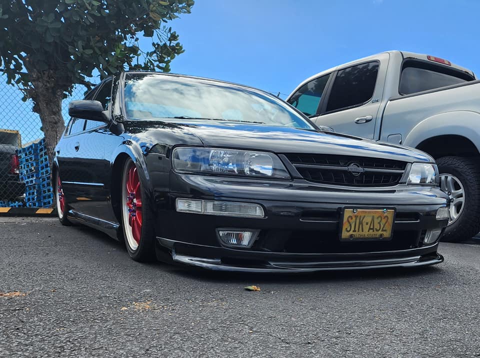
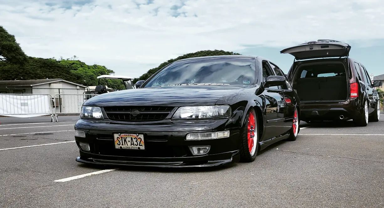
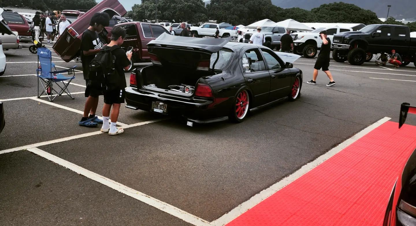
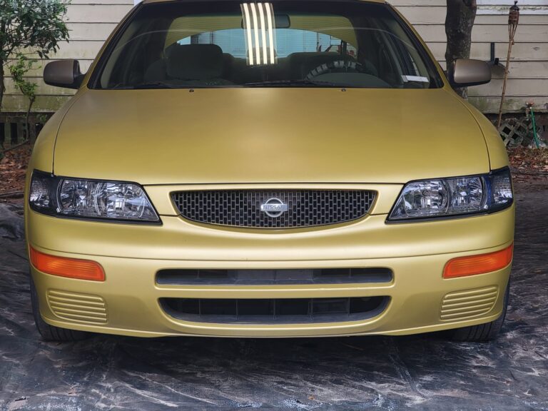
Well I got my AEM FIC running finally after a week of messing with it, and it does run a 4gen maxima and the timing works on it too. Neat little set-up and a good option vs eManage.
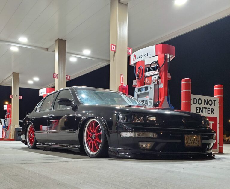
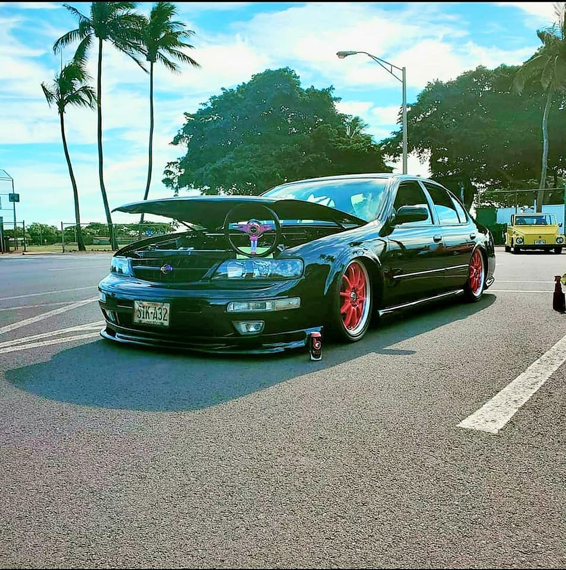
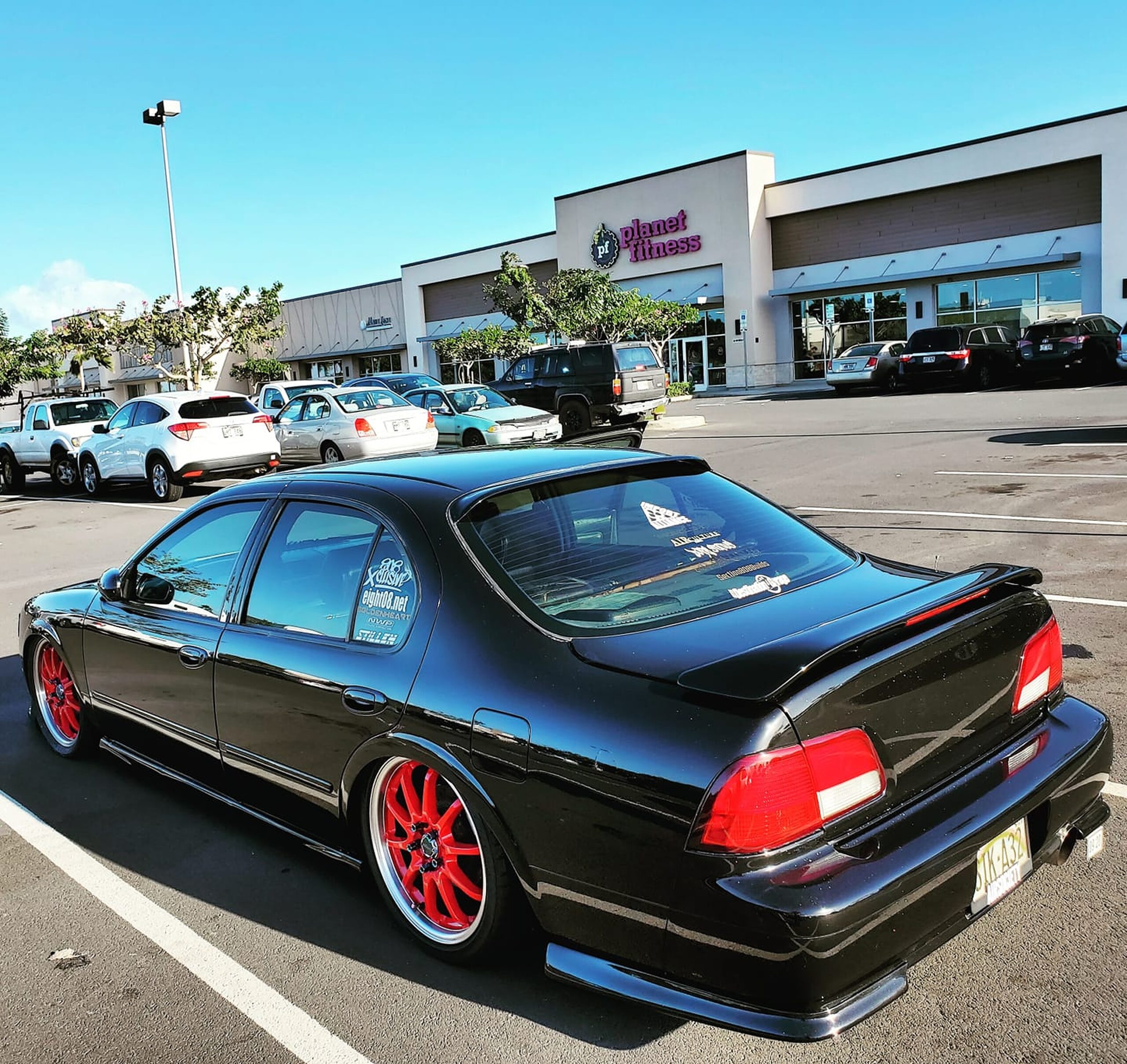
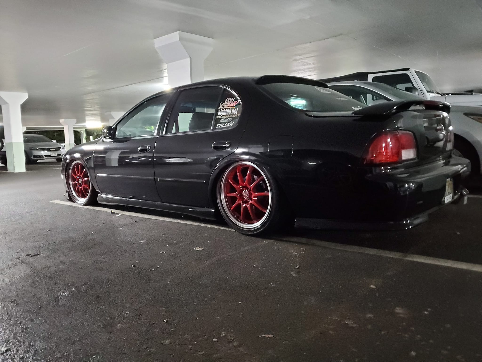
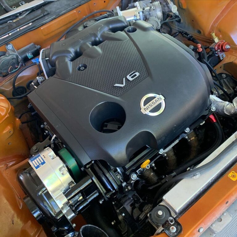
I’m running it on my 1996 maxima with a z32 MAF, 410cc injectors and a t3/t4 custom turbo setup.. and I have a 2008 3.5l in there out of a 2008 maxima.. with a pathfinder tb.
Finally got in to the 12s with my car NA yesterday. The atmospheric conditions were sick, though my traps left me a little disappointed I was hoping I’d see 105-106mph, not sure why this car isn’t making as much power as I expect it to, maybe the 3.0 cams really are a limiting factor, but I was ripping it out of the hole anyways and managed to run a couple 12s as well as a bunch of 13.0s. Pulled the best 60’s I’ve ever pulled, all 1.7s and a lone 1.6. My car was a big hit with people convinced I was spraying and searching for the nitrous line.
Anyways, my setup is:
2002 VQ35 with 3.0L cams and 3.0L cam timing equipment and VIAS Blockoff plate
Y-Pipe
Autozone cone filter on a stick
3.0L Throttle body
Custom 3″ from the flex section back
ACT HD PP and ClutchNet 6 puck sprung hub
TRE trans built by yours truly w/ Quaife LSD and PPG 3rd and 4th straight cut gears (TRE detailed, deburred and shot peened stock 1st, 2nd, 5th, TRE shot peened PPG 3rd/4th)
M&H 8.5x26x15 slicks at about 11.5psi on some random 15×7″ wheels
Stock 3.0 ignition timing and mid to high 12s AFR (coarsely tuned, my laptop has been dead for a year so I cannot fine tune my emanage, so I just set the AFR to mid/high 12s using the little dials on the front of the emanage).
No weight reduction other than no AC (which is going back in this winter) and stuff like lighter wheels, coilovers, Fidanza flywheel, etc.
I was launching the car at 5500rpm slip-dump, then tried 6000′ on my 1.69 60′ run and it still held. Never did try higher than that. Probably should have tried redline just to see what it would do.
Weather was ridiculous yesterday, that’s why I went to the track when only 1 other person could go with me. my buddy jason who has a really nice turbo 3rd gen. his brother took videos so hopefully I will have those soon.
Temp 43F, dewpoint 25F, pressure 30.33 made for a nice low DA of -600 feet LOL. It was actually even lower earlier in the day, but I got to the track later than I wanted. Oh well.
Something else weird, on my first 4 runs (including my 12.92) my car was breaking up between 5000and 5500rpm. I don’t know what that’s about. I’ve never experienced that before but I rarely floor this car on the street so who knows. Maybe old plugs or something, really not sure and I don’t remember it happening on my last 2 runs.
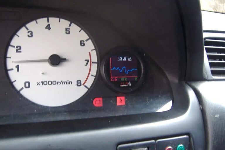
The factory gauges are about 1.25-1.5 inches deep – the circuit board sits that far back from the black plastic surface on which the gauges are mounted (the circuit board mounts on the back of the white plastic part of the “sandwich”, probably more than 1.5″ away from the black surface on which the gauges are mounted – no need to modify it in any way) Once you remove the factory gauge there is tons of room (depth) to mount a gauge in it’s place, The PLX gauge only takes up about 3/8 inch of depth.
I’m happy to say that I finally have a 6 speed swap under my belt now. This one was done on a buddies ’99 (deloa84), so I thought I’d show what I did differently than the procedure in the write ups. In my opinion my changes are cheaper and easier than the alternatives.
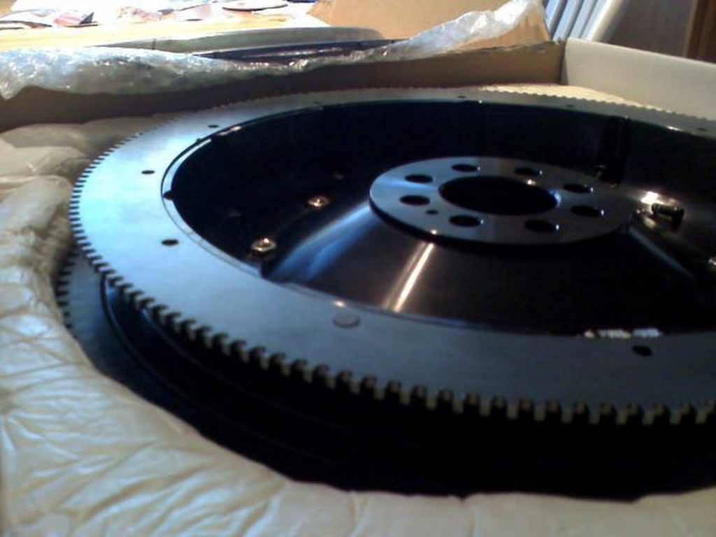
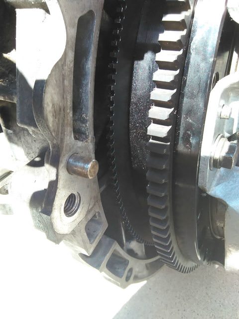
The main hurdles I’ve identified with the swap are the timing ring and the transmission mount.
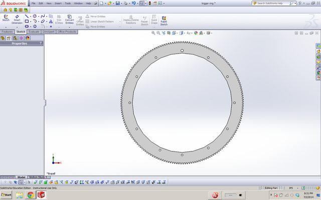
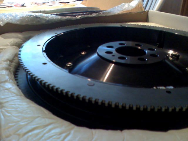
For the timing ring, I drafted it up in my favorite CAD software and had it cut at a local machine shop. It is just a matter of unbolting the old ring off of a 6MT JWT Flywheel and bolting the new one on.
Everything else in the swap was completed as usual.
Parts used for this swap:
02-03 HLSD Maxima 6MT
FWD JWT Flywheel with my custom timing ring
JWT Clutch
02-03 Shifter Cables
02-03 Shifter
Ralco STS
ES Shifter Bushings
One piece SS Clutch line
Last but not least, a short vid of it back on the road.
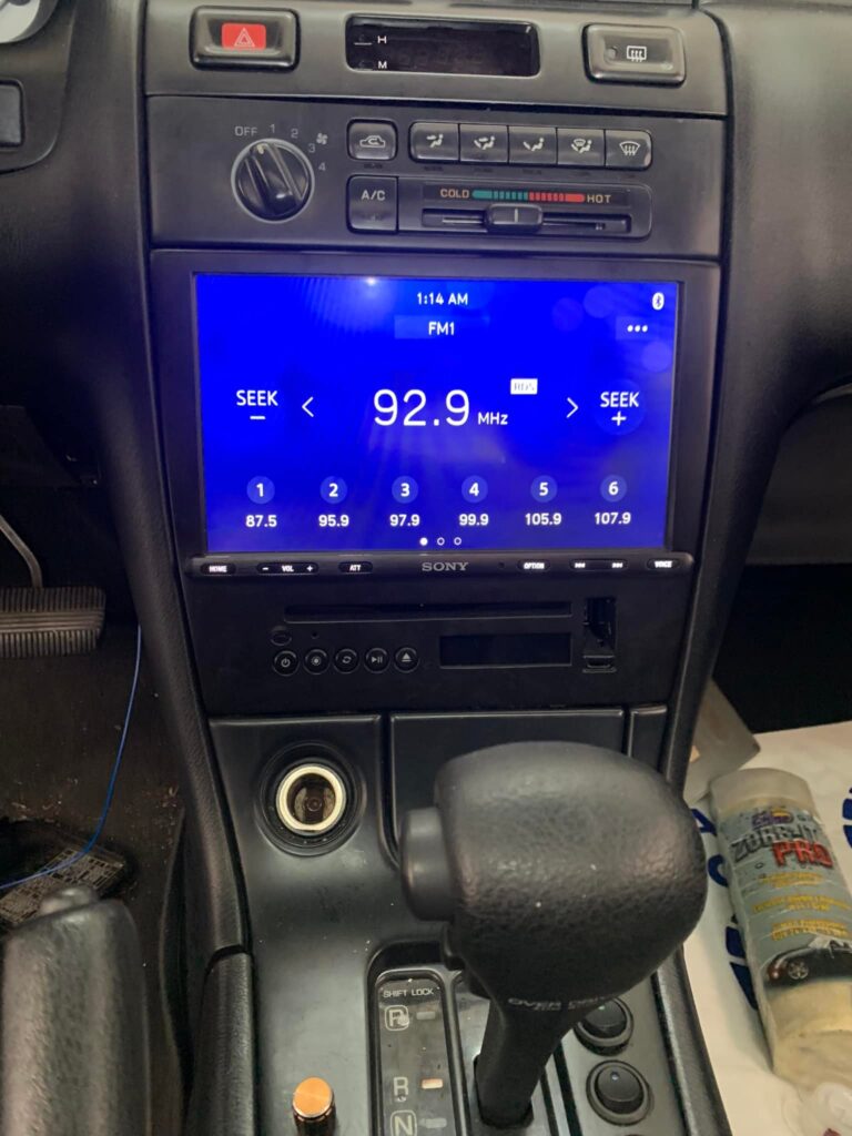
Before and after shots! Finally got my new head unit installed, a completely custom flush-mounted Sony AXV-AX8100 along with a VSI CD player. Still have a few details to deal with but it’s in and playing. Complete write-up coming soon!
Brief Details: What can the device be used for:
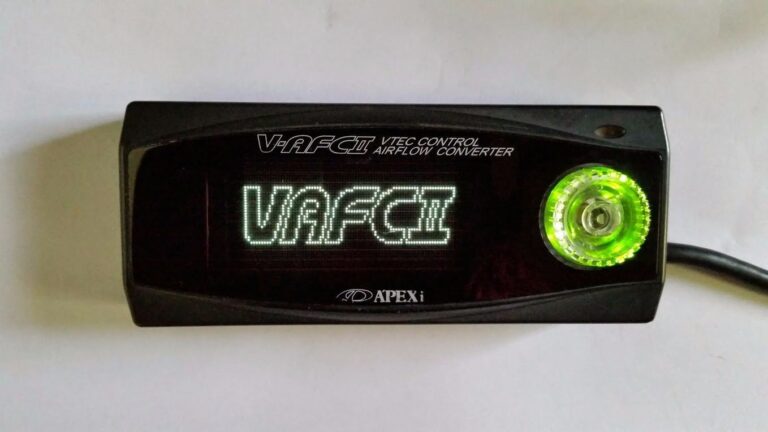
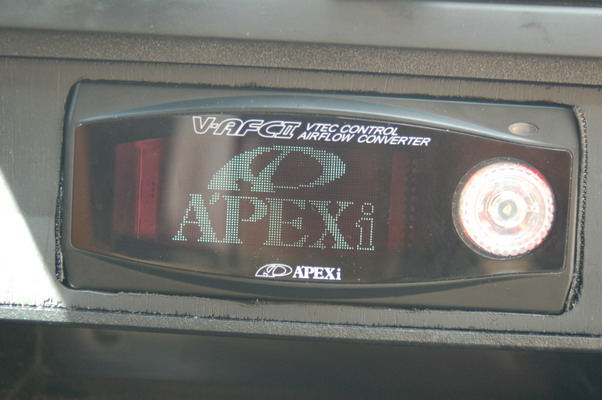
In the VTEC AFC II, the VTEC changeover point of a vehicle with a VTEC engine (in our case 00VI/MEVI) can be adjusted at an optional engine RPM. This fuel adjustment controller can increase and decrease fuel in a wide range of +50% to -50% by 1-point increments for the specified engine rpm. RPM points can be set in 100 rpm increments and make fuel correction according to the throttle position.
The second-generation SAFC is a fuel computer that adjusts fuel/air ratio by modifying the air-flow meter/MAP sensor signal. The SAFC features a user-definable, eight-point, adjustable fuel curve that can be set in 500 RPM increments. The range of fuel adjustment is +/- 50% at each of the user-defined setting points. On hot-wire vehicles, the Deceleration Air Flow Correction function is capable of curing the erratic idle and stall problems associated with open-atmosphere blow-off valves on hot-wire air-flow meter systems. The SAFC is capable of monitoring and replaying the following data channels in Numerical, Analog Meter and Graph displays: Intake Manifold Vacuum/Boost Pressure, Air Flow Capacity, Intake Manifold Pressure, Karmann Frequency, Engine RPM, Throttle Position, and Air Flow Correction %.
Tools Required: Necessary components used to install the VAFC to an A32:
Wire cutter
Wire Crimper
10(or 12mm) socket and ratchet
Soldering iron with 16-22ag solder
Electrical tape
Snap connectors
Warning: I am not responsible if you fry your electrical system or damage your engine. Use caution when working with electricity and please disconnect the battery before proceeding!
Installation: Installing into your 1995-99 Maxima
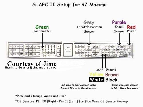
You will need to access the passenger side of the ECU so from the passenger side of the car remove the kick plate to reveal the sealed harness to the ECU. Undo the 10mm socket from the center of the harness plug and separate the harness from the ECU. Pull off the clear plastic shielding which encases the wiring and we will begin the taping of wires for your new S/V-AFC II.
From here you will need to match up accordingly the wiring from the V-AFC II Harness to the wire location (NOT COLORS) on the ECU harness. Please note that you will not be using the Light Blue, Purple, or Orange wires from the V-AFC harness, tuck them away. Take note of subscript on ECU harness image for the location of Blue(O2 sensor hookup wire). Solder all wires securely and cover with electrical tape. Below are an V-AFC wiring diagram, an S-AFCII wiring diagram, and also the pin-outs on an A32 ECU harness, please use them properly to match up the wires. Failure to do so will result in damaged electronics or engine.
Initial V-AFC II Setup: Before you can start the engine you will need to setup the V-AFC.
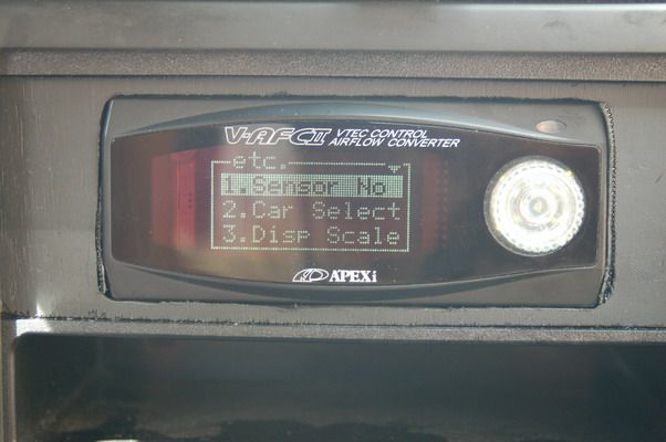
Now that you have securely solder all the necessary wires to the ECU you may now begin the setup to make sure you do not damage the engine on startup. Turn ignition to the ON position but DO NOT start the engine and your newly installed V-AFC will come alive. Navigate through the menu’s, be sure to take it slow as not to incorrectly configure a vital setting. Move to the ETC menu; hit right on your joystick, scroll down and continue into Initialize, and toggle over to Yes. Accept the choice, after doing so wait 5 seconds and turn the ignition to the OFF position. Doing so will clear any unwanted information stored in the device if you happened to purchase the device used.
Return the ignition back to the ON position but DO NOT start the engine. Your V-AFC will activate again for more information to be stored. Navigate into the ETC menu again, and proceed to enter the following:
Sensor NO: 4 IN, 4 OUT (Assuming you are running a A32 MAF) –Otherwise*1*
Car Select: 6 Cyl, Arrow UP and RIGHT, V/T 1
Sensor CHK: Ensure sensors are giving readings
Further tuning settings will need to be fine tuned while on a dynamometer. Once all settings have been checked over, turn the ignition to OFF wait 5 seconds and return the ignition to ON one last time. While your V-AFC is booting let the throttle rest at 0% for 10 seconds, and depress the throttle to 100% for 10 seconds and release. You have now completed the learning sequence for throttle positions and you can proceed to start the car.
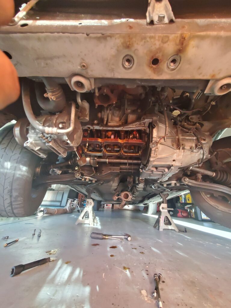
Doing my upper oil pan gasket. For anyone that needs to do theirs, there’s only one pain in the ass that’s in your way. After taking the ac compressor off, the ac compressor bracket, center support, y pipe and lower oil pan, the only thing left holding the upper one on after removing all the bolts is the fkin dust cover for the axle. In the last picture you can see i had to knock it back away from the axle seal because the corner of the upper oil pan was sitting above it and ha.