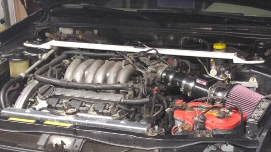
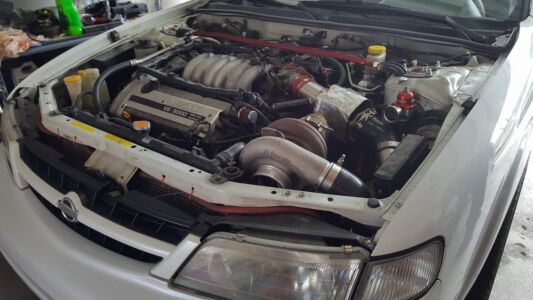
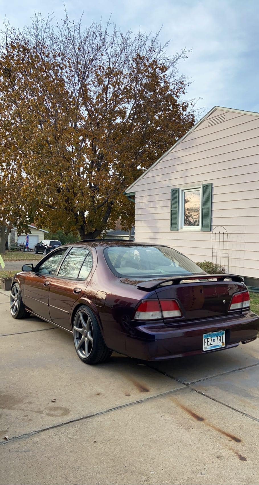
Owner: AJ Hall
Year: 1995
Model: Maxima
Color: Burgundy
Engine: VQ35DE
Transmission: 5-Speed Manual
Trim: SE




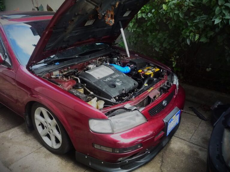
Owner: AJ Hall
Year: 1995
Model: Maxima
Color: Burgundy
Engine: VQ35DE
Transmission: 5-Speed Manual
Trim: SE
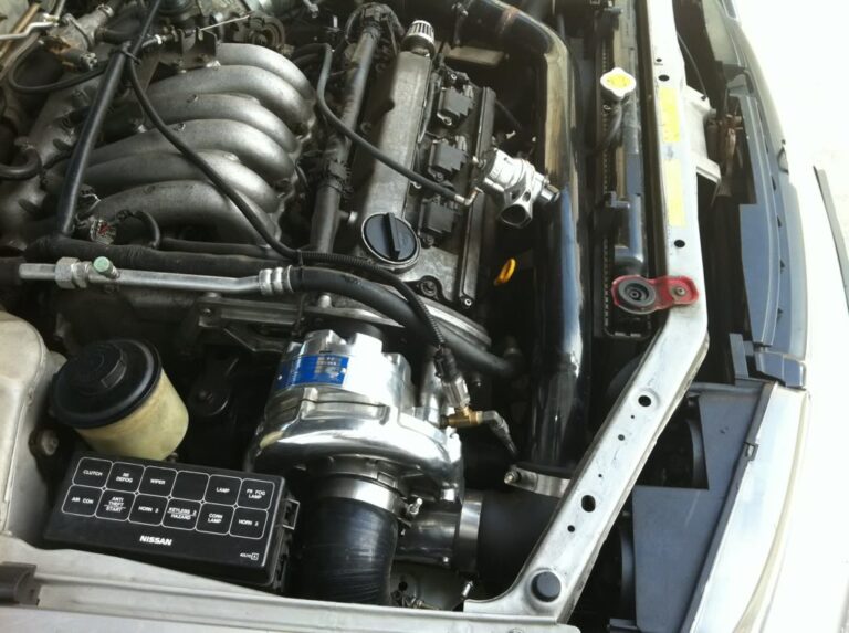
Owner: 1998MAXSE
Year: 1998
Model: Maxima
Color: Sterling
Engine: VQ30DE
Transmission: 5-Speed Manual
Trim: SE
Note:


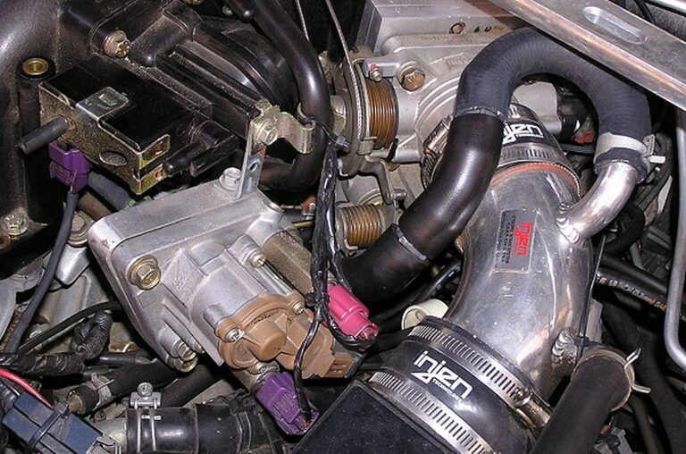
Credit: boredmder
.org member Curt has come up with a unique way of mounting his 4th gen IACV with the swap, as well as routing hoses. Here is his idea…
Lots of discussion and controversy about where to route the air from the 4th gen. IACV to the UIM, and I don’t know if there’s any one answer. But here’s mine and the logic behind it.
First, the what. I used the 4th gen. IACV with a Stephen Max adapter mounted hanging from the end of the VIAS. I kept the 3/8″ brass nipple that Steve had pre-installed, since I was confident in his experience and knowledge (and to also mention his intelligence in thinking these sorts of things through). The output hose from the IACV was routed underneath the UIM runners, exiting from under the #1 cylinder runner by the chain cover end of the engine, then looping around back to where the plastic nipple is on the end of the UIM that applies vacuum to the brake booster. I T’d the IACV hose into that line just above the plastic nipple.


Now, the why. Here’s the logic of why I tried (and have been completely satisfied with) this setup. An engine is, in simple terms, and air pump. These 3 liter engines at idle try to pump almost one cubic foot of air per second. With the TB butterfly closed, the engine is straining to suck in air from wherever it can get it.
On startup it initially gets only a tiny amount from the brake booster as all that’s really happening is creating a vacuum within the brake booster. And even if the engine sucked all of the air out of the booster (in effect creating a perfect vacuum), that would only be a fraction of one cubic foot. Secondly, once there’s a vacuum created in the brake booster there’s a check valve in the vacuum line between the UIM and the brake booster that’s intended to keep the booster from losing the vacuum.
Now let’s assume that you’re cruising down the road with little vacuum in the UIM (in other words, heavy throttle) and for some reason the brake booster has been having its vacuum bleed off. If you were to try to brake with your left foot as you kept the right foot on the accelerator (not recommended), the brakes wouldn’t likely have the boost assist necessary and stopping would be a problem. But it used to be that most people learned to drive using their left foot only for the clutch so that if sometimes they were driving a MT car and sometimes an AT car, they wouldn’t get their feet confused in a panic situation.
So, properly using you right foot to stomp the brakes, even if the brake booster had been real short of vacuum when your foot was on the accelerator, as soon as you lifted it to apply the brakes, the butterfly plate in the TB would have closed and in an instant there would have been good vacuum in the brake booster unless there was sort of a problem beyond the check valve at the booster (and having the IACV plumbed into the booster line wouldn’t affect that kind of a problem anyway). Simple logic persuaded my to try this setup and I’ve had no regrets.
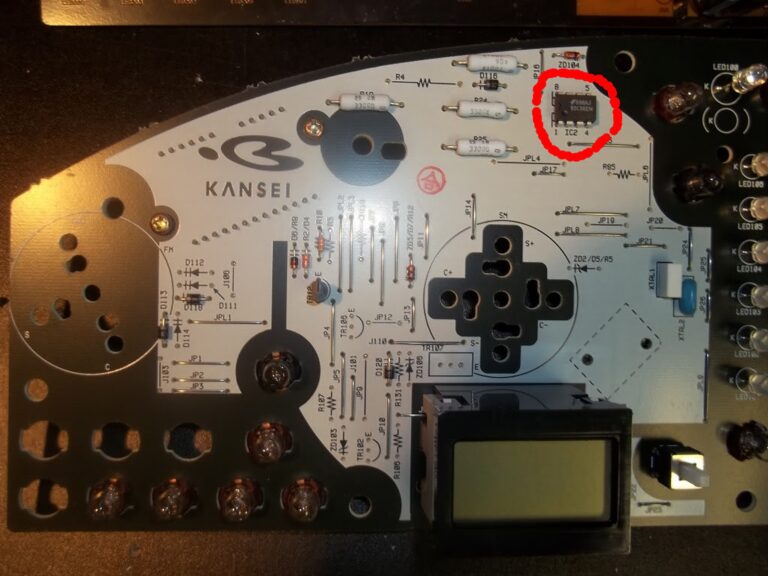
Credit: TunerMaxima3000
You need to pull your gauges out, simple enough to do. Get the cluster in hand, then disassemble the plastic surround.
The back side of the gauges is basically a big circuit board, there are screws holding your gauges on (should be), they’ll be a goldish color. You’ll need to very gently remove the screws for each gauge, store them in a safe spot, such as a Ziploc bag.
Now you can gently remove the circuit board from the gauges and gauge face. Set the gauge face back into the cover piece to protect it for storage.
Now flip over the circuit board, it will be one of the two below, I’m pretty sure it’s the first one:


Now all you have to do is de-solder the chip. LABLE THE CHIP WITH MARKER OR SOMETHING, so you don’t get them mixed up. You should also note or take a picture of the orientation, but since I’ve posted it for you you can just reference this if you need to.
It’s soldered on the reverse side, use solder wick or a solder sucker and keep going from pin to pin removing the solder until it all looks pretty much gone. Then warm the pins as you gently pry on the chip with a precision screwdriver, applying even pressure and only lifting straight out.
The big thing here is to NOT HEAT THE PINS TOO MUCH! If you do, you’ll damage the chip. Don’t let this scare you away, but just be aware that it’s not hard to overheat them, so use FLUX PASTE, it’ll make the job so much easier. Doing it without means sitting there for a while warming the crap out of it before the solder flows. So use the paste, or you’ll mess something up
When you get the chip out, it’s cake, just do the same and swap it over. Be sure to label the chip you want to use so you don’t get them mixed up
Assemble in reverse order.

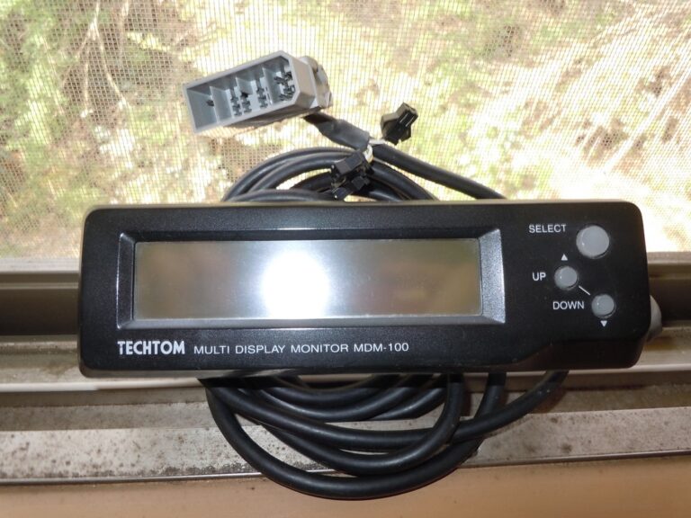
A Techtom MDM-100 Monitor allows the driver to view a number of engine sensor parameters in real time using ECU data. It is plug-n-play and installs in seconds! Long recognized as the most advanced monitor for Nissans, the MDM-100 allows you to watch two different parameters/sensors at the same time, and in real time.
Important Note: This only works on 1995-1996 Nissan Maxima ECUs.
PDF Document: MDM100N1inst
Features:
Within seconds you can have the MDM-100 plugged in and displaying engine readings on its easy-to-read backlit LCD. You can see 2 sets of readings on one screen. Additional ECU data is easily obtained using the easy-to-operate 3 button control. Examples: Speed and Water Temp Battery and Ignition Timing.
| Functions of Techtom MDM-100 | ||
|---|---|---|
| Screen Display | Parameter | Unit Measured |
| SPD | Speed | MPH/KPH |
| RPM | Engine RPM | RPM |
| AFM1, AFM2 | Air Flow Meter | Voltage |
| INJ1, INJ2 | Injector Open Time | Milliseconds |
| IGN | Ignition Timing | Degrees |
| WTEMP | Water Temperature | Fahrenheit |
| ITEMP | Intake Air Temperature | Fahrenheit |
| BATT | Battery | Voltage |
| THP | Throttle Position Sensor | Voltage |
| O2S1, O2S2 | O2 Sensor | Voltage |
| O2-1, O2-2 | O2 Sensor Condition | Lean/Rich |
| IDL-SW | Idle Switch | On/Off |
| NTL-SW | Neutral Switch | On/Off |
| POWERST-SW | Power Steering Switch | On/Off |
| AIRCON-SW | A/C Switch | On/Off |



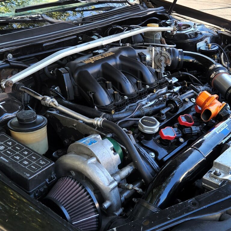

This post is dedicated to Brandon Presson. He passed on February 13th, 2023. He was a really good guy, super knowledgeable and very passionate about Maxima’s (especially the love he had for his original 98 Maxima in this post). Such a big loss for the Maxima community. We send our deepest condolence to his friends and family.



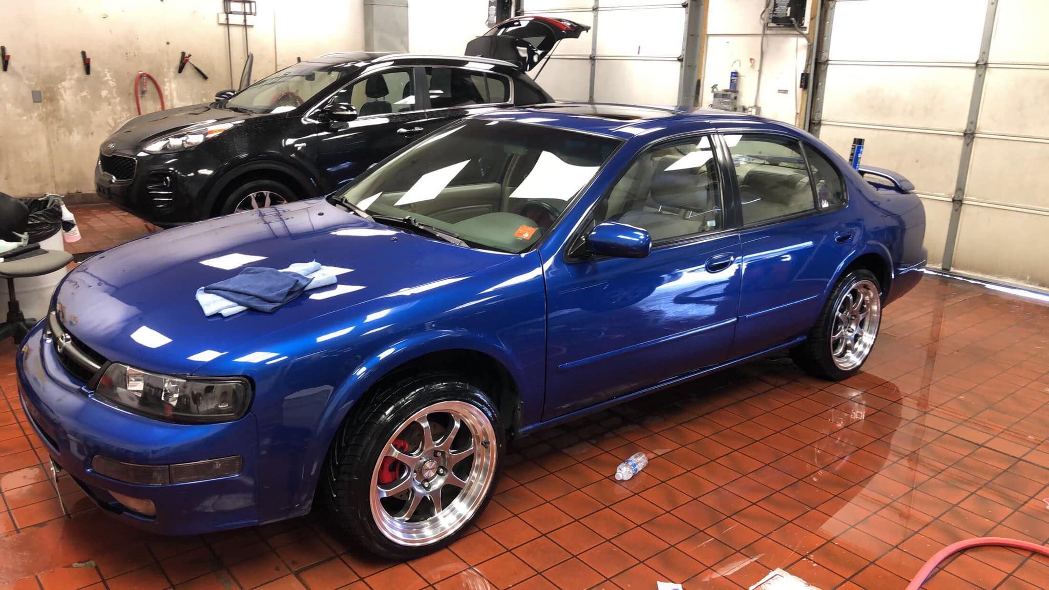
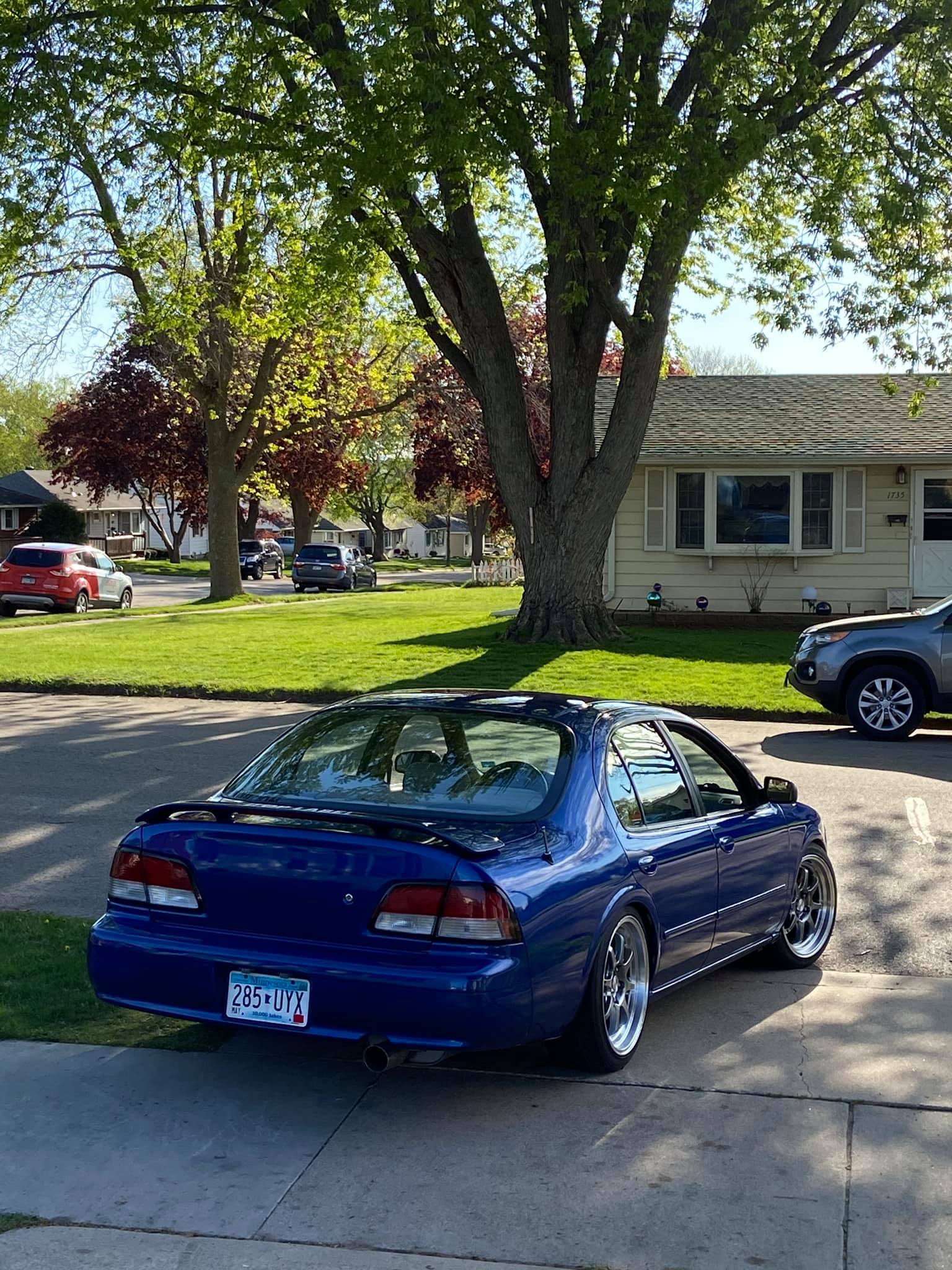
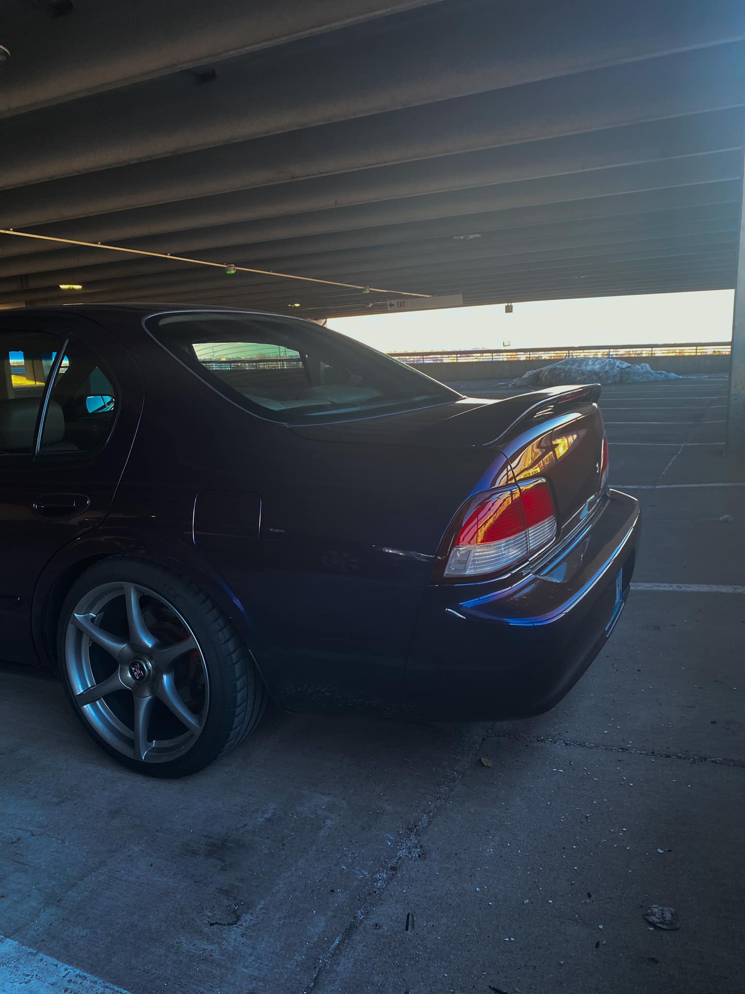
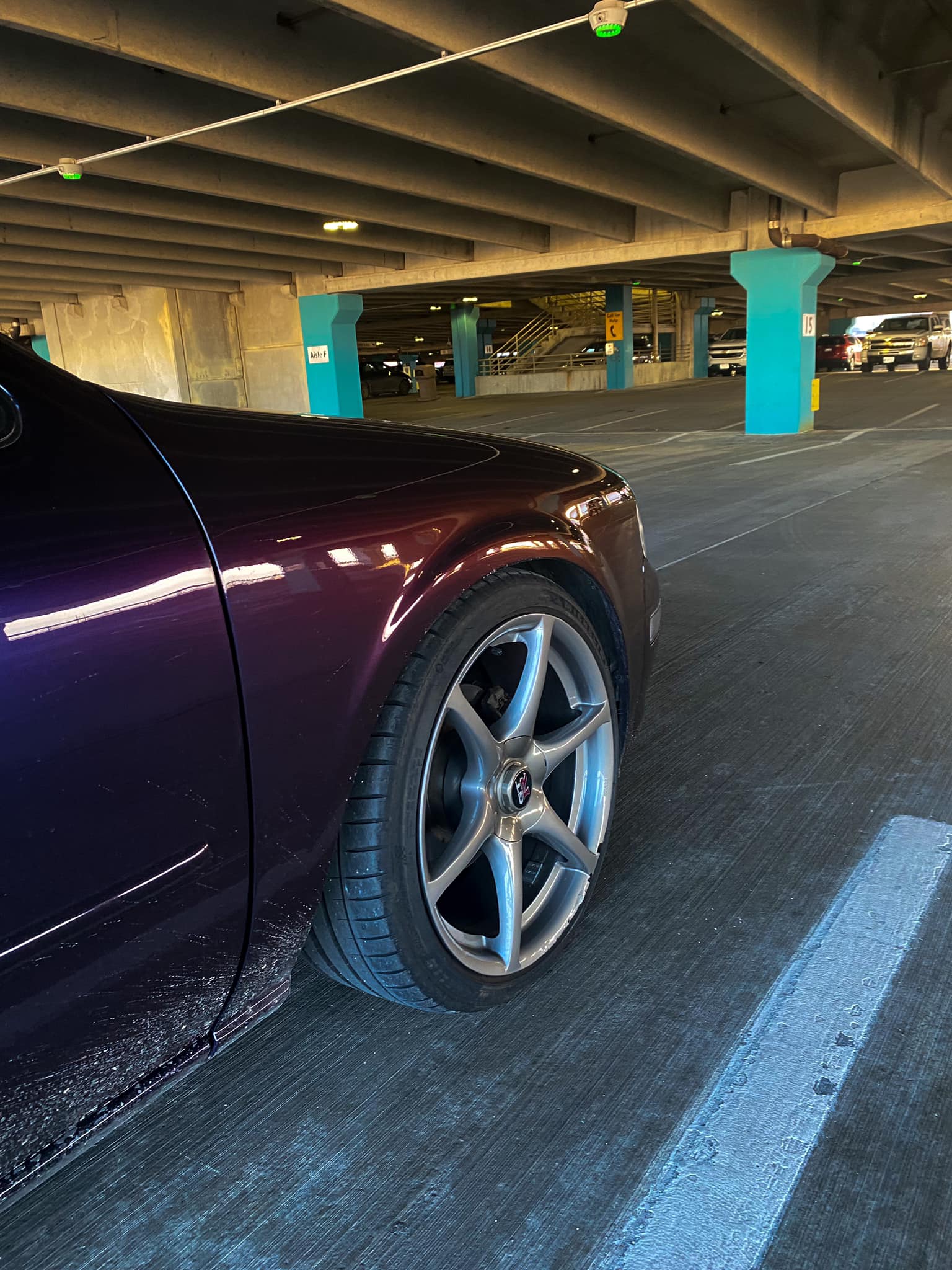
Owner: Efrain Carrillo
Year: 1999
Model: Maxima
Color: Stage 3 Midnight Purple
Engine: VQ30DE
Transmission: 4-Speed Automatic
Trim: SE

















Order Link: https://www.hcspeed.com/products/nissan-maxima-i30-i35?variant=39733222637729
Price: $45.00
Notes: