Tag

Intakes, Headers & Exhaust

Browsing

Member Credit: Greg

Changing the spark plugs on a 2002-2003 Maxima is not something you should have to do until around 100,000 miles. The stock plugs are platinum tipped and should last a very long time. Replacement of the plugs is something that Nissan recommends you “see your dealer” to do. The reason is that in order to replace the 3 plugs in the rear cylinder bank, the intake manifold upper and lower collectors have to be completely removed from the vehicle. To do this requires skill beyond the average Sunday mechanic, since there are many vacuum, electrical and coolant lines that have to come off in order to perform the job.

My car had slightly over 18,000 miles on it when I did the job, and it did not really need new plugs. The reason I ended up doing this job was because I strongly suspected one or more of my ignition coils were faulty, and try as I might I could not get Nissan to admit the problem or come up with a solution. I called Courtesy Nissan, ordered a set of ignition coils and plugs, and set about doing the job myself. I replaced all 6 ignition coils, and doing the spark plugs as well was simply for the sake of completeness.

I documented the entire process with pictures and text so that if there is anyone out there who wants to do the same, perhaps they will not be quite as intimidated as if they were going in cold. The job is not simple, and took me about 3.5 hours, but I did take a lunch break, and was also documenting the process with a digital camera.

Cost of the job was also not cheap – a set of 6 ignition coils from Courtesy Nissan cost me $333.48. The required gasket is another $18.40. The plugs themselves will run you $11.00 each. If all you really need to do is change your plugs, obviously you don’t need to buy coils, so then all you would need would be 6 plugs and the gasket. Do the job yourself and you will save quite a fortune in labor, as this job performed by the dealer would be many hundreds of dollars.

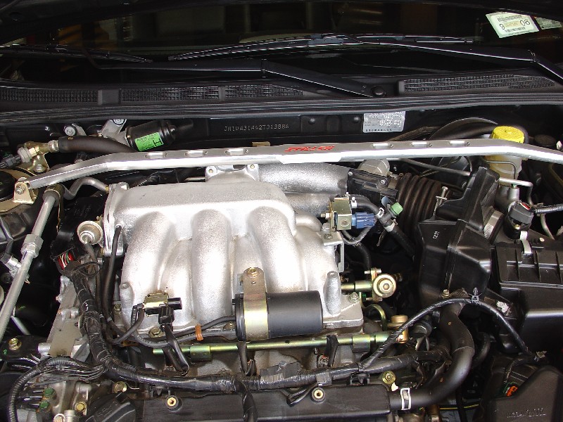
Here is the nice clean engine bay before going in with the chainsaw. If you have a front strut brace, as I did, it is probably not necessary to remove it, but I did simply to make it a little easier to lift the collector out. It only takes a minute or two anyway.

This pic still shows the strut brace in place (I removed it later). First step is to remove the 4 allen bolts securing the engine cover, and take it off.
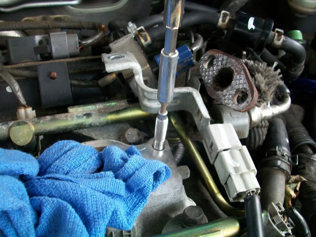
A view near the firewall. The test is if you can reach and loosen these two bolts then you can do the rest of the job. It requires a 12mm socket with a long handle.

My method of doing this job will show you how it can be done without disconnecting so many vacuum lines, as I have seen others do. All you need to do is take a few parts off first so you can reach the bolts that attach the collector to the engine. Leave the electrical connector off, but put the valve back on.

Same idea with the vacuum tank. Take it off only so you can reach the attachment bolts. Then put it, and the VIAS control solenoid valve back on.

Once you get these 3 bolts, and 2 nuts off, you can go ahead and put the VIAS and vacuum tanks back on the collector.

Don’t take these off! No need to. You’ll see why later.

Two vacuum lines which need to come off. Slide the compression clamp down, and twist the hose off. Easy.

These electrical connectors need to be popped off. Be careful you don’t break them.
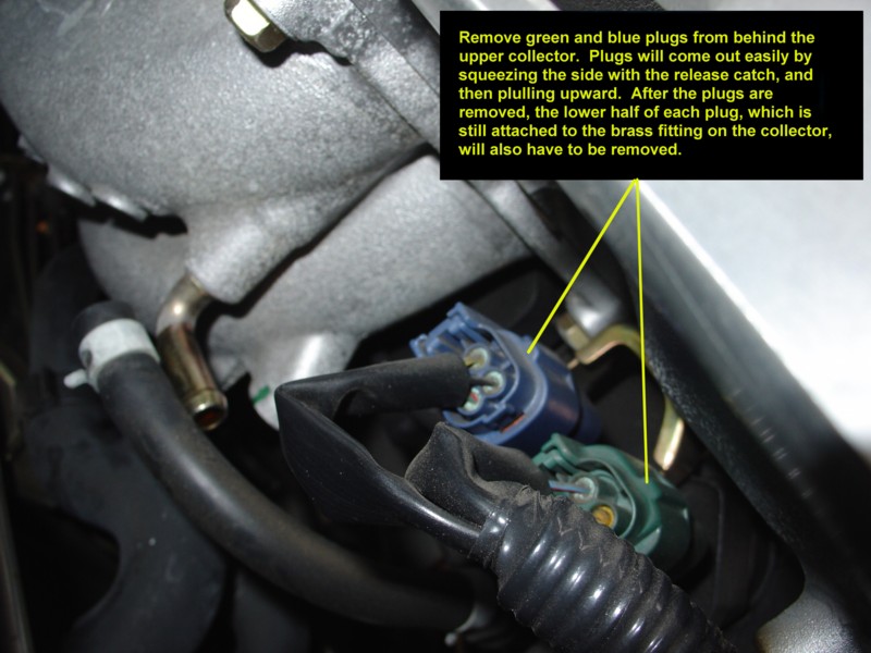
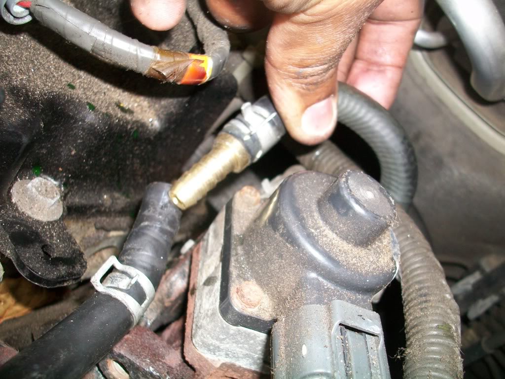
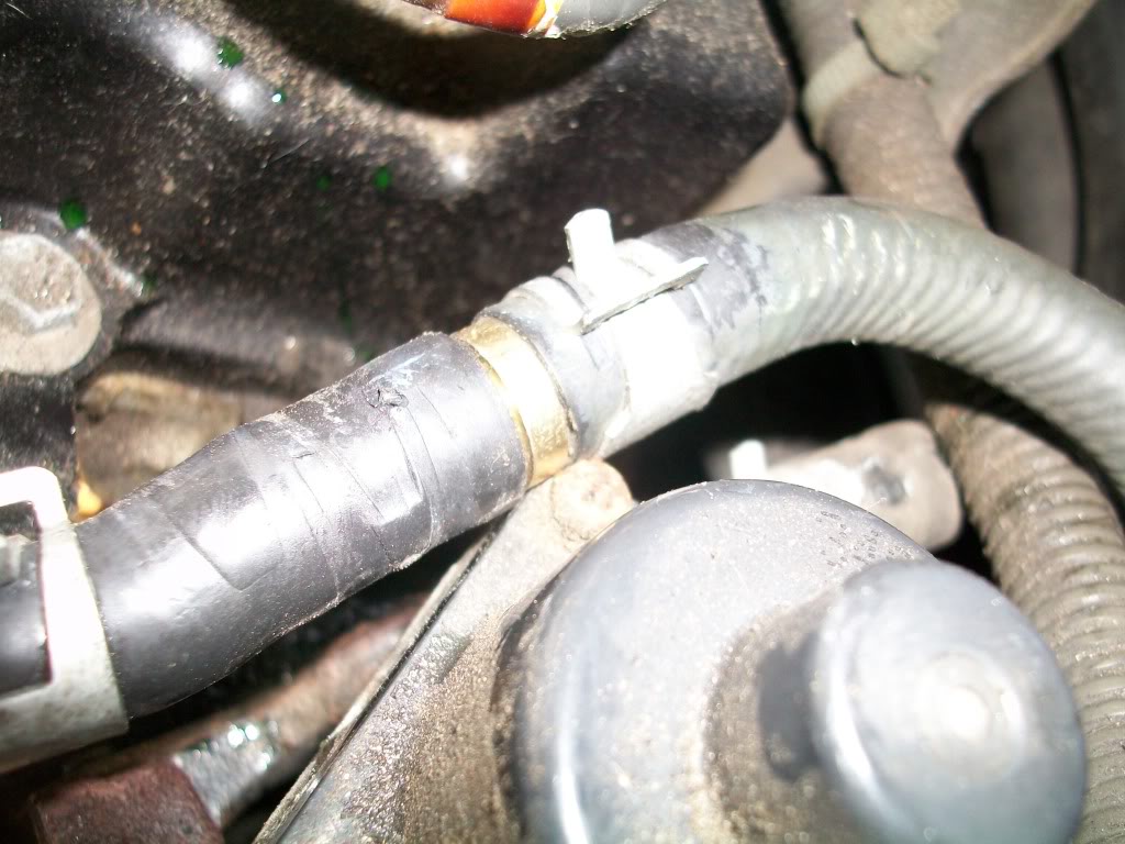
You also have to release and then slide the lower half off their brass fitting, or you won’t be able to lift the collector assembly off.

Again, another picture before going in with the chainsaw.

Loosen the screw holding the rubber connector to the intake. Leave the other side alone. It will stay.

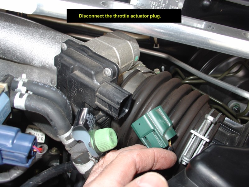
Unplug your “drive by wire” electrical connector, for the electronic throttle.
Pop out the two plastic harness holders.
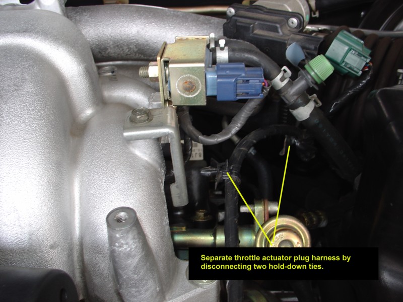
Get the wire out of the way.

Remove this plug, take the 10mm bolt out, then put the plug back in.

Make room…..


This was a tough picture to take. A little trick here – disconnect hoses 1 and 2 right at the area pointed to by the yellow line. Be prepared for a little bit of coolant to spill out when you disconnect hose #2.
Important – disconnect hose #3, not where you see the yellow line here, but at the other end of the hose. You will never in a million years reach this hose where the arrow is pointing, but you can reach it at the other end.

Slide the compression clamps down before you try to take these hoses off.
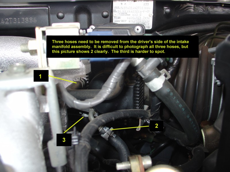
Just another view at lines #1 and #2.


Removing hose #1.


After all of the hoses and electrical connectors come off, you can lift the entire intake collector assembly up and out.

This is what the engine bay looks like with the collector assembly off.


Another view of the engine bay.


The collector assembly is rather large, but it is actually very light. I took the opportunity to clean mine up with some Gumout intake cleaner. Note that hose #3 is still attached to the collector!
Note how all of the assemblies remain attached when the collector comes off.

Here is a side view.

The procedure to remove the coils is the same for the front bank as it is for the rear. Just take the 10mm bolt out, unplug the connector and pull it right out.


This is what one coil looks like.


Use a spark plug wrench to remove each plug.


Nissan recommends you change this gasket any time the collector comes off. It is an expensive gasket, but why risk it? Buy a new one.
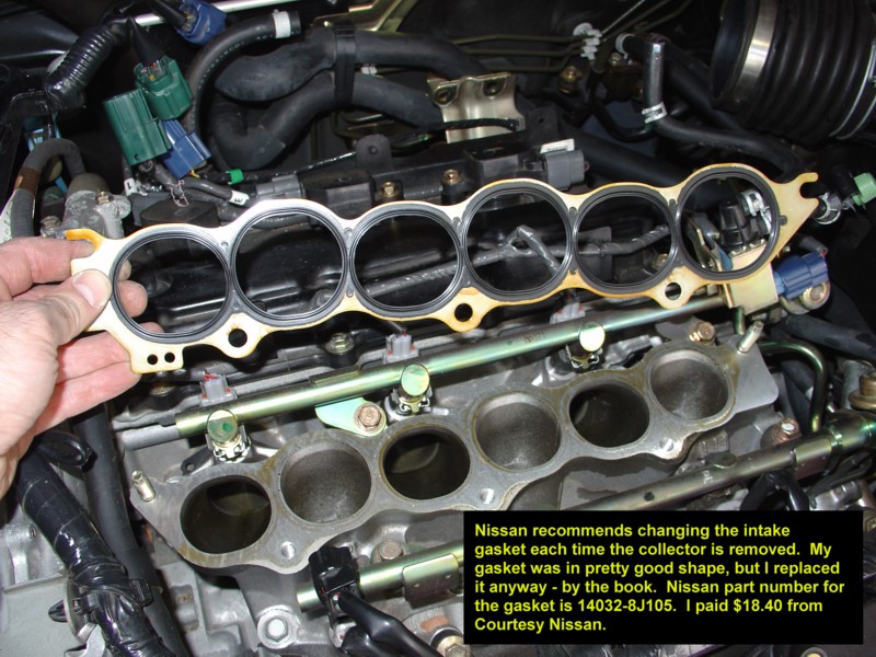

I do not show re-assembly here, but just follow these steps in reverse order. I hope I have de-mystified this process a little bit, and that you might be inspired to do this job yourself when the time comes. Good Luck, and you can do it.

Loading

Member Credit: Greg

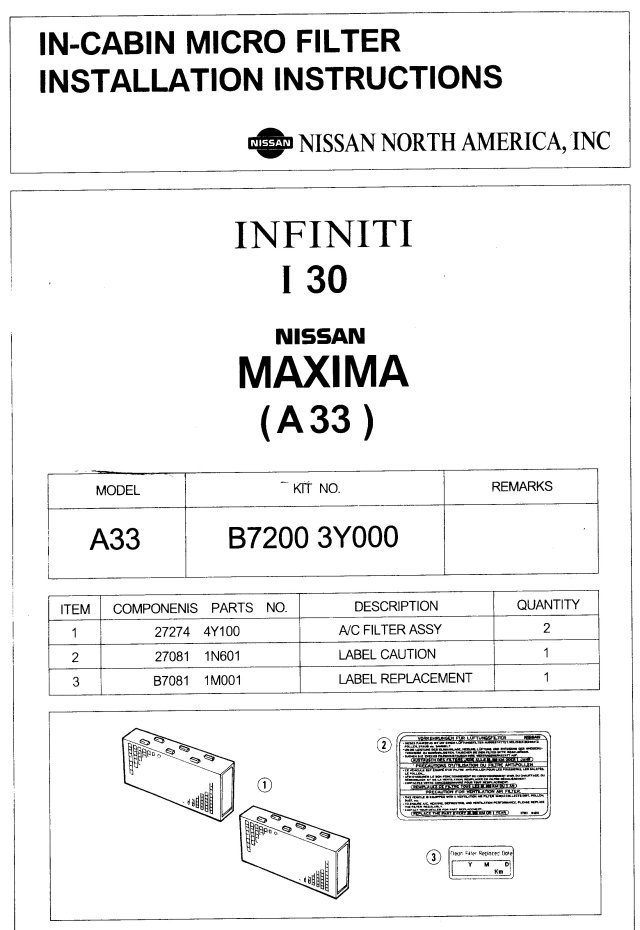
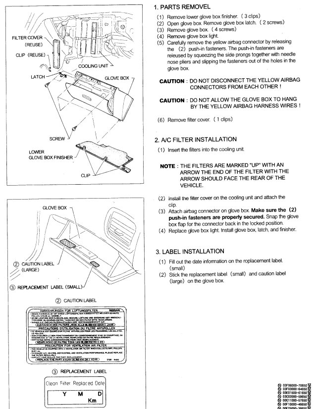
These are the Nissan-Supplied instructions for the In-Cabin Microfilter. They are somewhat generic, and were not 100% accurate to my car. The only difference was that my car did not have the “Glove Box Finisher”. Besides that, everything else was correct. Perhaps the Glove Box Finisher was eliminated in later 5th-Gen Maximas?

I bought my filter at a Nissan Dealership. The cost for one of these babies is $58.74!!! Cheaper deals can probably be had on the Internet.

Nissan recommends changing this filter approximately once per year. This procedure is not listed in the owner’s manual, as Nissan prefers this operation be dealer-installed. With only a Philips screwdriver, if you are the least bit competent you can do this job yourself and save the money. The filter alone is expensive enough!!

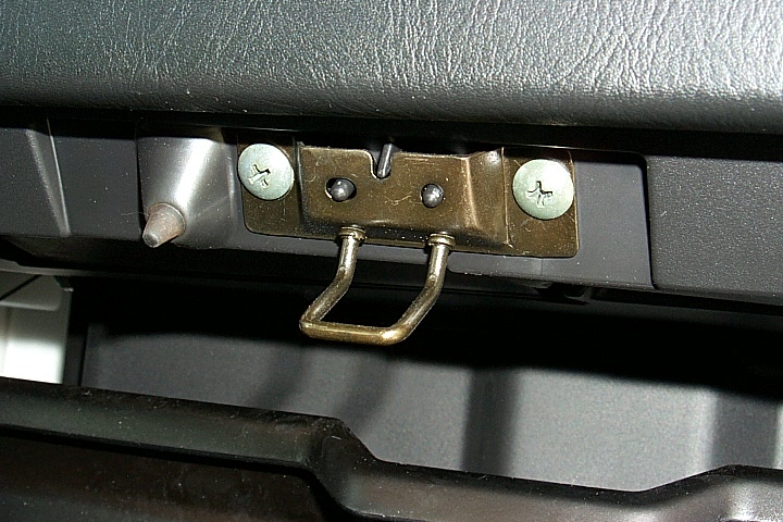
Start by removing the glove box latch. 2 screws and it’s out.

Next, remove the 4 screws holding the glove box in place. There are 2 at the top and 2 at the bottom. You will have to disconnect the glove box light, and the air bag connector. Both come off easily, and the entire glove box can be removed.

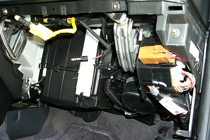
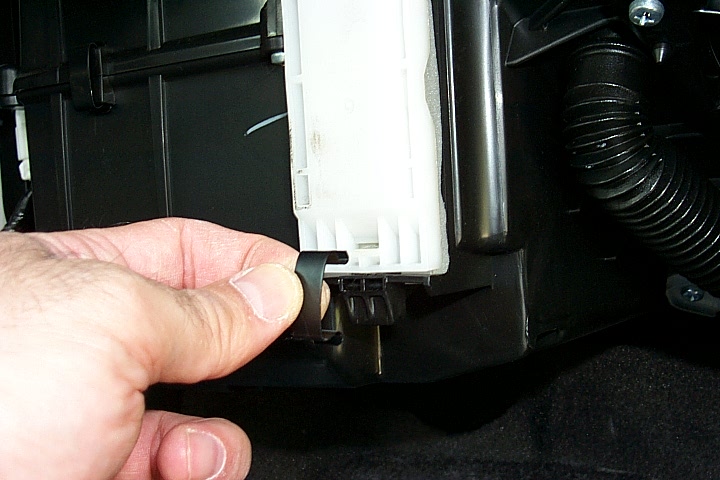
Once the glove box is out, the next step is to pop off the metal clip holding the white filter cover in place.

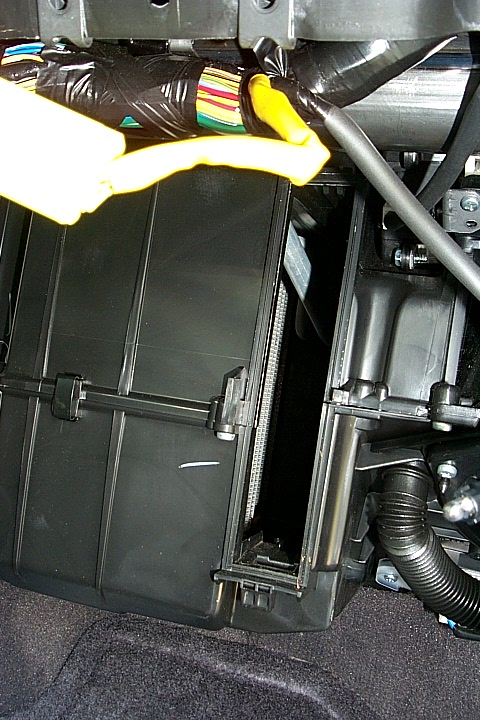
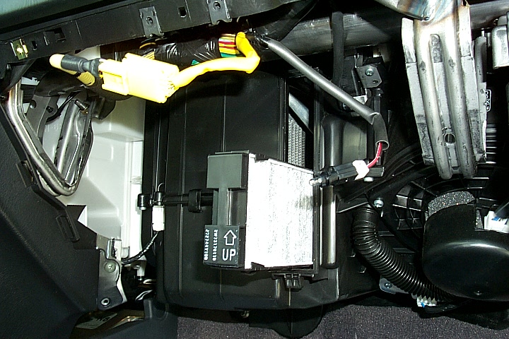
Now the filter can be slid out. Apparently, the microfilter put in at the factory is a single piece, and does not look like the factory replacement filters you will put back in. In fact, the replacement filters look much nicer (higher quality). This picture shows the empty hole where the old filter was.

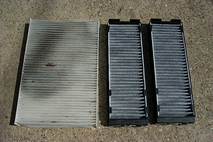
This side-by-side shows the stock filter removed on the left, and the replacement filters on the right. I was quite amazed at how dirty this filter got. The replacement filters come in two pieces, and have plastic holders that enable them to slide into place more easily than the original filter.

My filter had all sorts of black dirt, crud and leaf pieces in it!!! And I keep this car garaged, and never drive it in the rain (if I can help it).
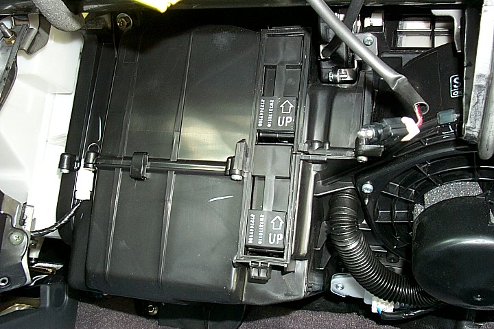
The easiest way to get the new filters in is to put one in at the bottom, then once it is in, slide it up into the top position, since it is difficult to get the proper angle to put the top one in directly.

Here is the completed filter installation, with both filters securely in place. Replace the white filter cover, glove box, reconnect the light and air bag connectors, and this installation is complete. Ahhhh, fresh air to breathe once again.

Loading

Member Credit: TEQ-NIQ

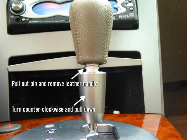
Step 1: Remove shifter knob – Shifter knob is made of two parts, the leather handle, and the lower aluminum-looking cone-shaped piece. Grasp the cone-shaped lower piece, rotate counter-clockwise and pull down at the same time to release from shifter handle. Once this is done, there is a small gold clip holding the handle in place, remove this and handle will slide off, remove this as cone-shaped piece.

Click the image to open in full size.WARNING: 
If you twist the shift knob thing as instructed you will end up breaking it. You just need to pull down on that plastic piece. There is a TSB addressing this issue.

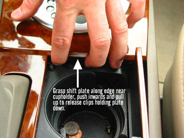
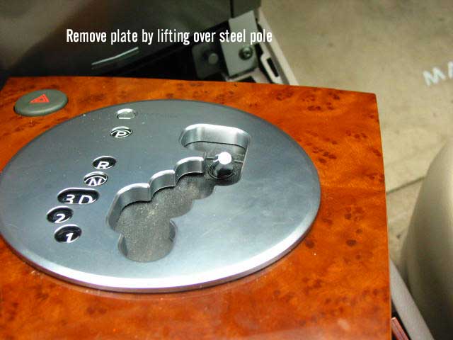
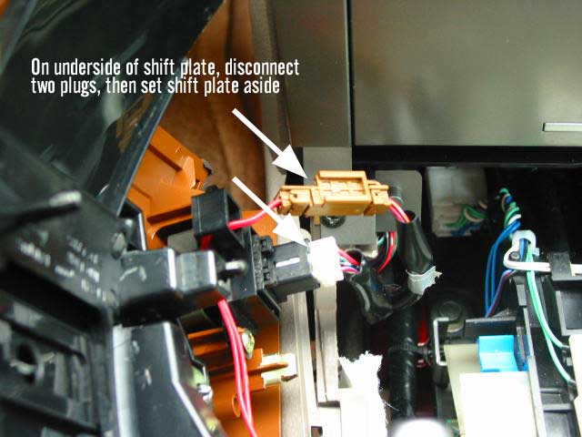
Step 2: Remove wood-colored faceplate and shifter piece – Open cup holder door. Using your fingers, press along edge of wood piece where cup holder door goes and pull up. Gentle but heavy force may be needed to pull up plate. Make sure you are slightly pushing the side of the plate inwards while you do this. Once you get the end of it released, you’ll need to put the key in the ignition, turn it till the air comes on, put foot on the brake and move shifter knob into the neutral position. Lift up the whole plate to completely release. Underneath there are two connectors, one brown and one white, that you will need to disconnect before removing plate. Set aside.

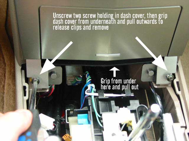
Click the image to open in full size. Click the image to open in full size.Click the image to open in full size.Click the image to open in full size.Step 3: remove two lower screws that hold the dash kit in place, place them in a safe place. Use fingers on inside of lower storage area (below cassette opening) to pull out the dash kit and release from its clips. Remove lower half first, then pull out upper half. there is another connector on the back of that piece that needs to be unplugged. Set dash kit aside.
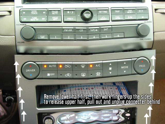
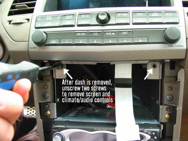
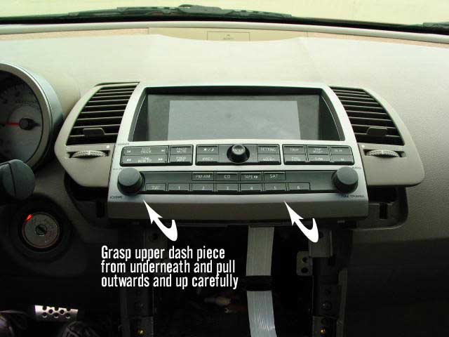
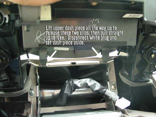
Click the image to open in full size.Click the image to open in full size.Step 4: Remove 2 screws holding in climate/audio control panel and LED screen. Holding this panel from underneath the radio controls, Pull piece outwards. The two middle air vents are also attached, and will come out as well. Lift out lower end first, then tilt upwards to release clips holding in the top edge. One connector on the back needs to be removed.
Click the image to open in full size. Click the image to open in full size. Click the image to open in full size.Step 5: Remove LED screen: remove 4 small gold screws on both sides of LED screen housing to separate screen from the rest of the panel.
Now you have successfully removed the LED screen. Pretty easy! To put back in, screw 4 gold screws back in, put whole panel piece back in first by inserting clips on top edge back through their holes, then slowly lower front edge down while making sure top edge stays flush with rest of dash. Carefully reconnect the plug, then lower all the way back flush. Screw back in the 2 screws. take Dash kit, reconnect wires, pop in the top part first back into slots, then lower part, then screw in 2 screws at bottom. Put the car back in neutral, plug in 2 connectors to shifter panel (brown and white), then slip shifter tube through the hole on the shifter panel, and carefully fit the panel back into place, starting with the edge closest to the dash and ending with the edge closest to the armrest/cup holder. Place cone part of shifter back over steel tube, place shifter knob on and carefully slide the gold clip back through the white part of the shifter knob, it should line up with the 2 grooves on either side of the knob and the 2 grooves on steel tube. Slide cone-shaped part back up and carefully rotate over gold clip until its tight. It may take a couple tries to get this last part right.

Loading

Member Credit: prjctmax

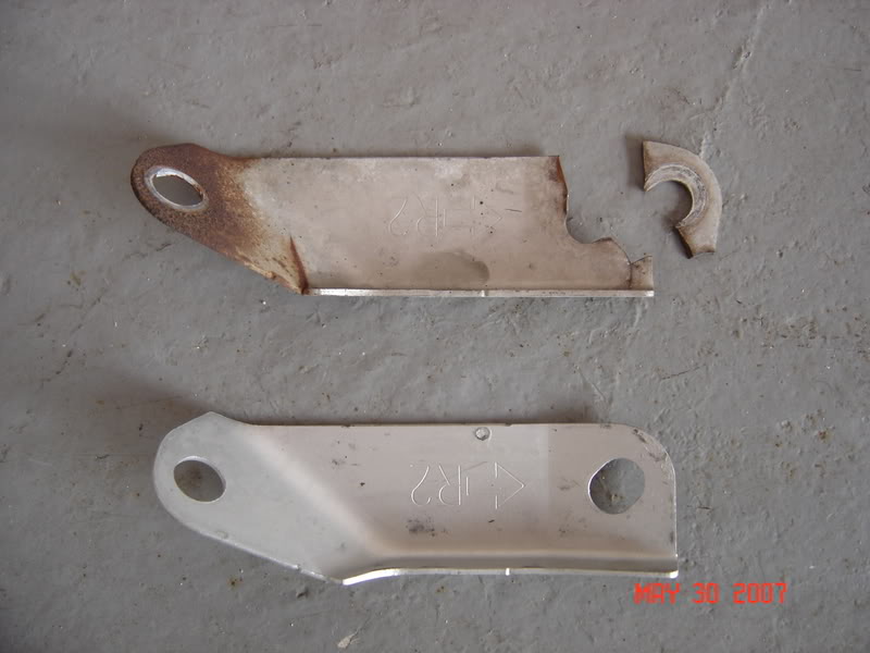
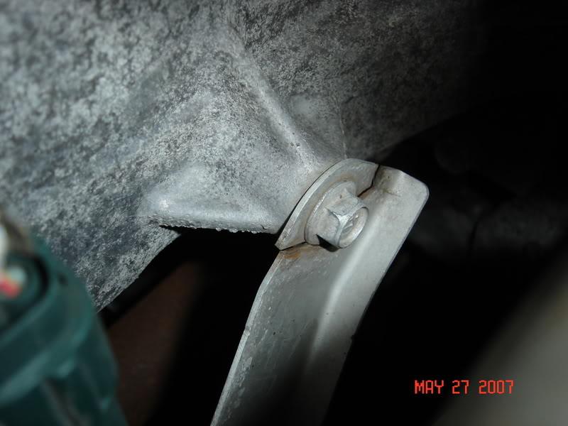
So I purchased the “gusset,” aka the broken bracket and installed it today.

At first I thought I had to take the y-pipe off in order to do so…bad idea since I do not have air-tools and I got every single bolt off except for ONE! So I lay under my car thinking and starring at the damn bracket. And I figured out that I could squeeze my hands through there and take the thing out with a little effort and time, since the room is very minimal to work with.

Tools needed-14mm ratcheting wrench (makes it easier) and a 14mm socket with a short extension

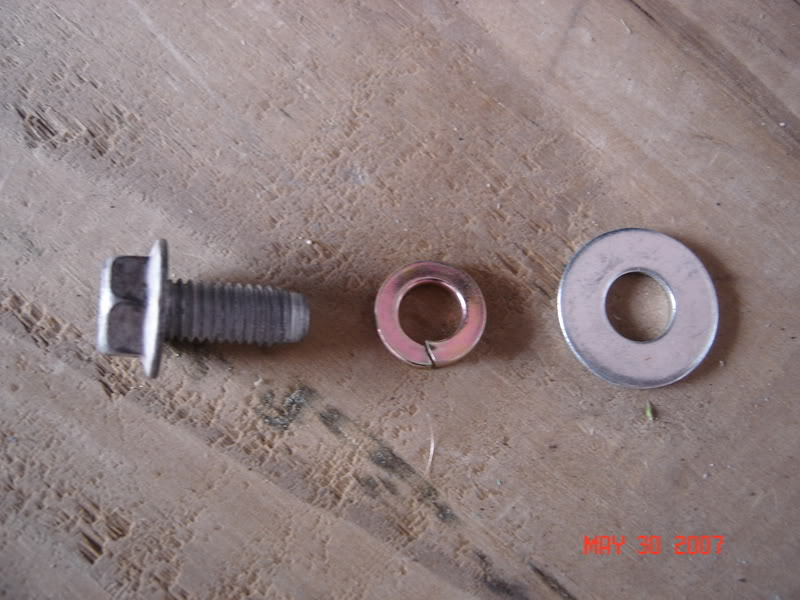
After I got both of them off I compared and this is the “old” and the “new”

Click the image to open in full size.

Judging by the huge crack where the bolt goes in I figured that I should put a washer and “lock-washer” (or whatever they are called) in for added surface area so that after time the bolt would not “eat” through the bracket again and snap that piece off AGAIN.

Click the image to open in full size.

I also decided to keep the front heat-shield off that was needed to take out the front 3 bolts from the y-pipe.

Here is the final “product”

Click the image to open in full size.
[IMG]And the noise at around 2700-3000 RPM is now gone![/IMG]

Read more: http://my6thgen.org/f277/how-fix-metal-metal-sound-gussets-2727/#ixzz4VC072nfZ

Loading

Member Credit: bone-daddy

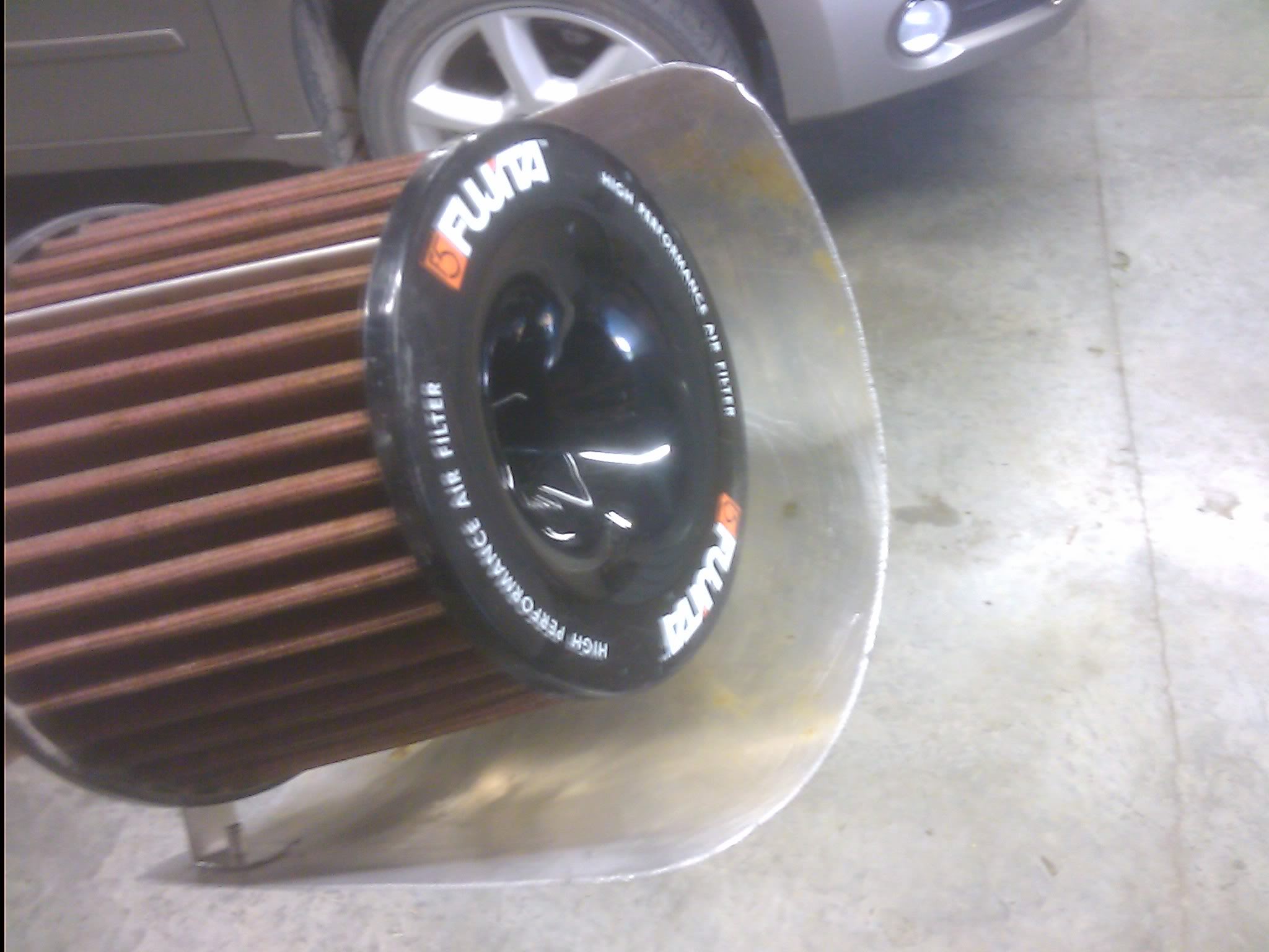
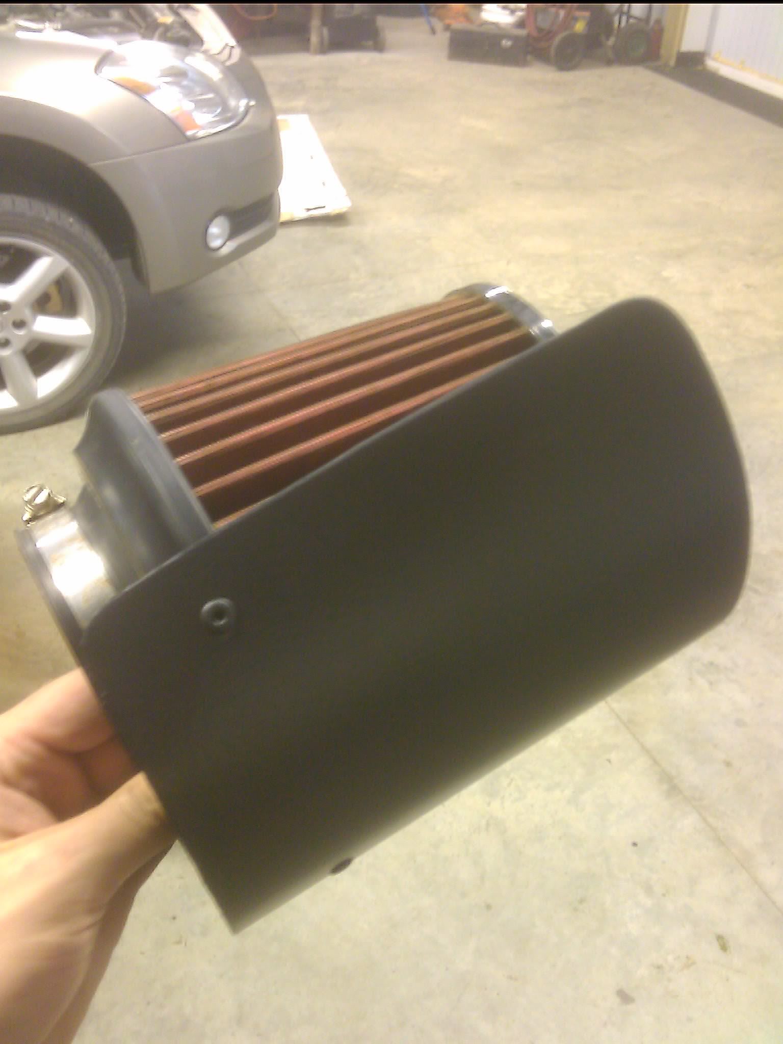
Ok so I have a Fujita CAI on my 04 SE, but my splash guard was broken a few winters ago, which a) I am too cheap to buy a new one, and b) makes getting at my air filter a LOT easier, but it also lets water in if I go through a car wash with and under body sprayer, so to remedy this, I built my own heat/water shield, and this is how I did it.

What you will need:
– Sheet metal or equivalent
–  Rivet gun and rivets
–  Drill bit sized for your rivets
– Something to cut the metal (snips, saw, cutting wheel)
– Vise
– Paint (optional)
– Grinder (optional)

I did the initial cutting before I figured I should take pics, but mainly this is how I did it.

Step 1:

First you must cut your main shield portion, I don’t have measurements but this is easily figured out by holding your filter next to the metal and seeing how tall you want your shield, once you cut it to that size, wrap it around your filter and see how far around you want it to go.

Step 2:

Now you need to cut the strips to rivet onto it, I would recommend starting with at least a 3 inch strip, mine were just shy of that and I wish I had made some longer ones, so I could put two rivets in each, but alas, I didn’t.

Step 3:

Once you have your strips, put them in a vice and then bend them into an sort of Z shape, with the end that attaches under the hose clamp only a slight bit larger than the width of the hose clamp, and if you can, put a slight bend on the very tip so it can’t slip out of the clamp. Test the fit by hooking the strips into the clamp while on the filter and hold the shield up before the next step.

Step 4:

Drill your holes and rivet the strips to the heat shield. Make sure the drill bit is the correct size for the rivets you have, if the drill bit came from a case where they slide into a metal index, you can test the rivet but sliding it in, you do not want any play for a secure fit.

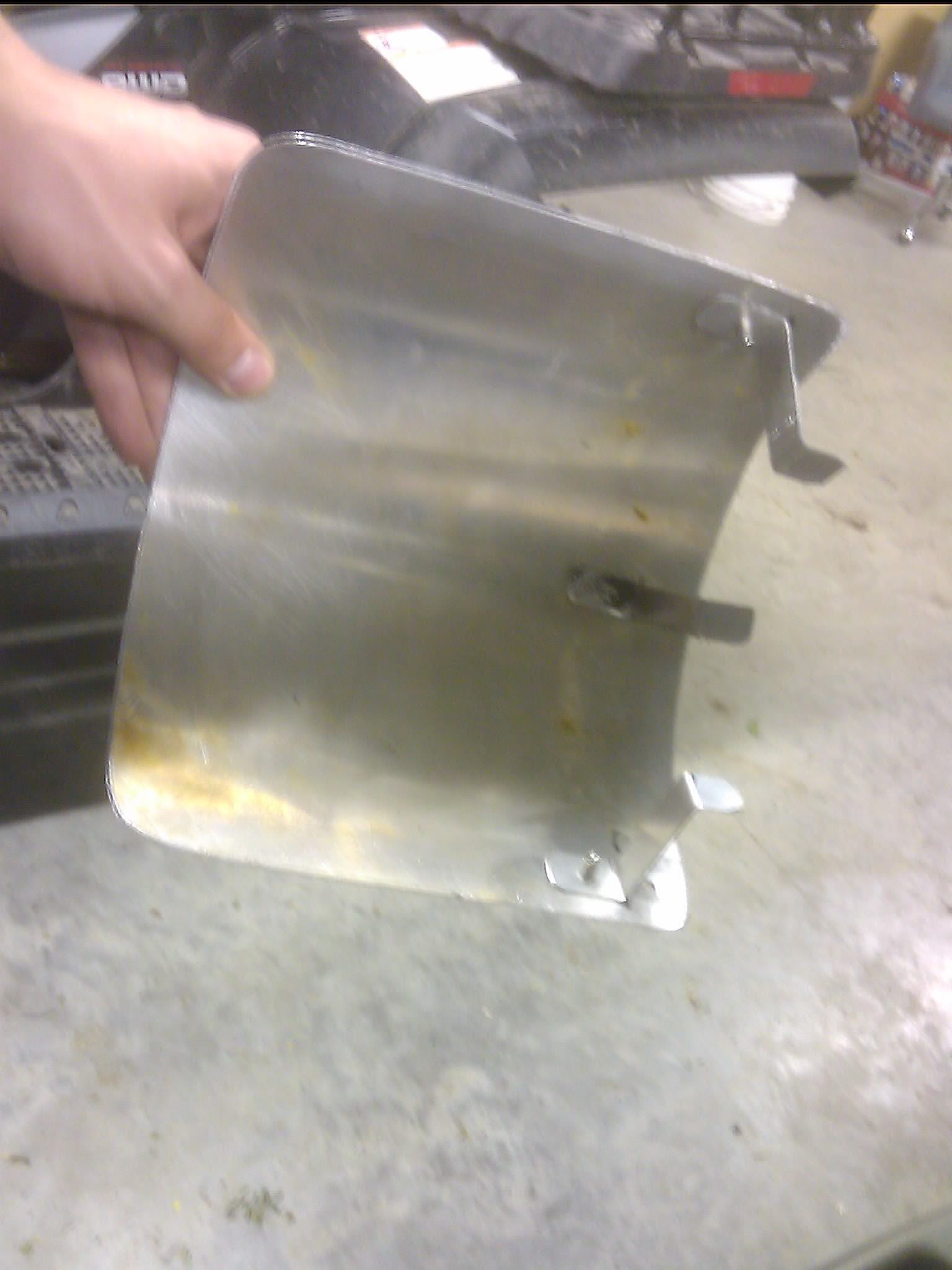
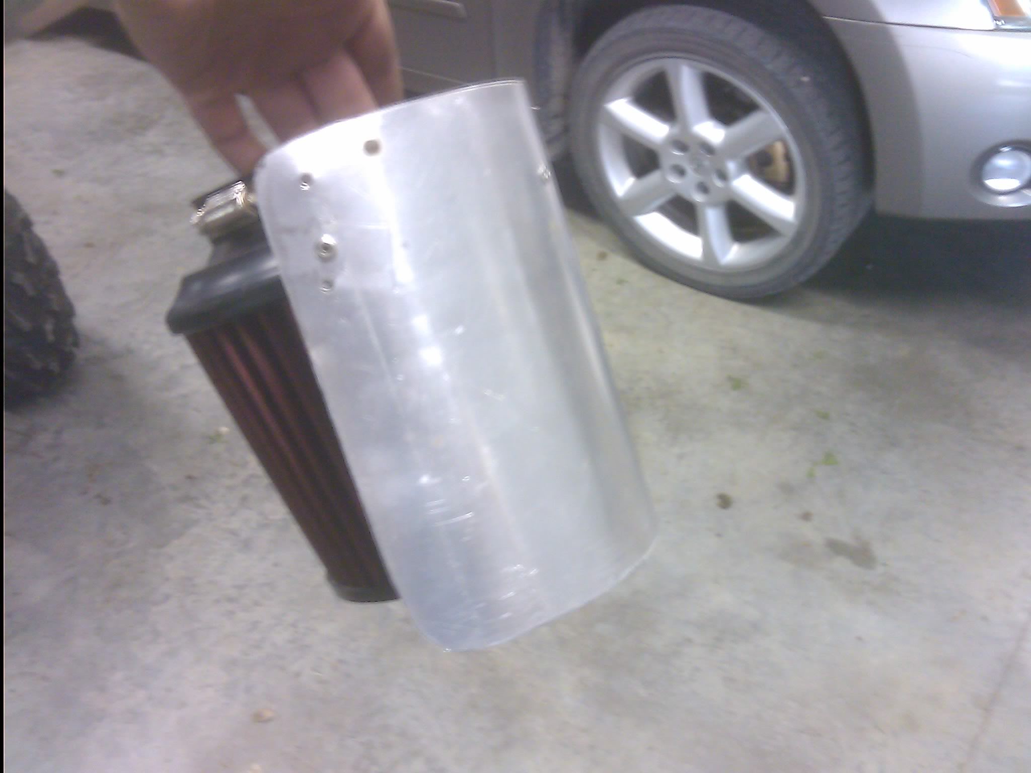
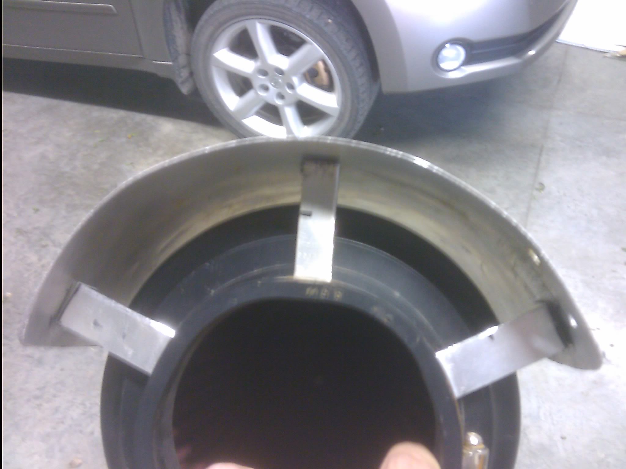
You should now have something like this:

Click the image to open in full size.

Click the image to open in full size.

Click the image to open in full size.

Click the image to open in full size.

And if you please, you are done! However, I was not please, so I painted mine with truck bed liner. Also note I rounded off all edges with a bench grinder since I used 1/8 inch aluminum and a cutoff wheel on an angle grinder to cut my pieces, which left nasty edges.

Click the image to open in full size.

Total cost of this was $0.00, I used an old sign backing for the aluminum, borrowed the rivet gun/rivets, and had the bed liner in the shop.

Loading

Member Credit: Chernmax

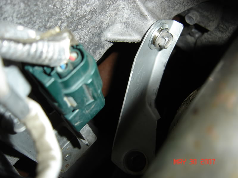
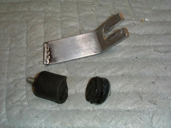
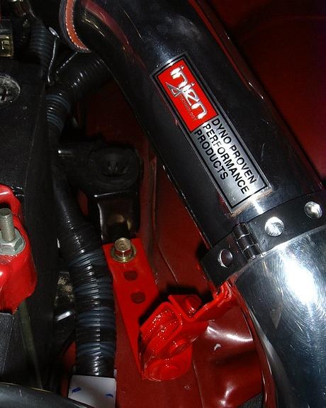
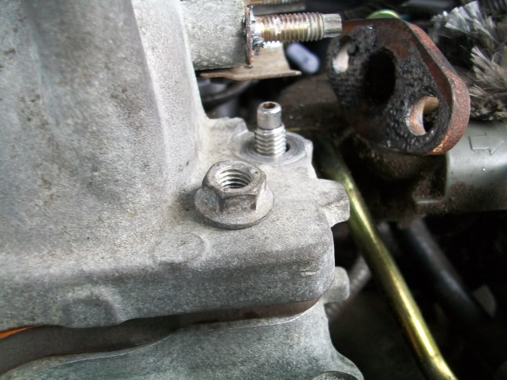
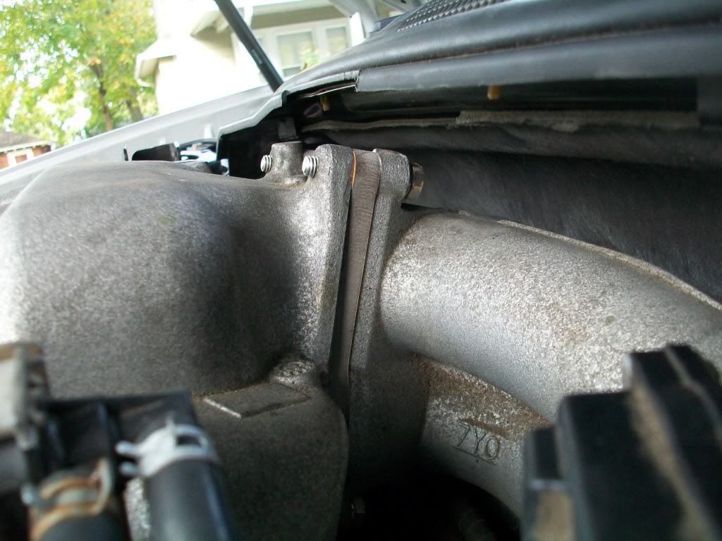
OK, the Injen CAI mounting SUCKS, driving vibration first took out the rubber boot mounting screw, I reinforced the mounting and the freaken weld broke… DAMM… So some of you might have this (see pic below)

Click the image to open in full size.

My Fix, about $20 clams:

Parts Used:
1- ROL Exhaust heavy duty tail pipe hanger.

2- 2 RE Works High Grade Aluminum Quick Release Racing Clamps

The task: Using a vice, I bent the Exhaust bracket in a 90 degree angle and attached it to the lower engine mounting bolt just below the Injen, using 1 clamp, I added a new forward midbody support clamp by hooking it around the Exhaust Hanging bracket U-hook, (The Rubber vibration spacer allowed it to twist nicely into place and is 50 times stronger than the stock shock mount).

Another benefit; the bracket is now mounted under the CAI and eliminated all stress on the mounting hardware. I also replaced the rear bracket (not required, however stronger), tightened down all. Job time, 17 minutes…
Click the image to open in full size.
Click the image to open in full size.

Click the image to open in full size.

Loading

Member Credit: CXJ Performance

DISCONNECT THE BATTERY FIRST!

This would be great time to change the spark plugs as well.

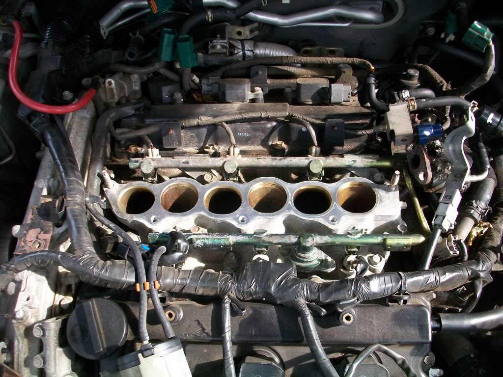
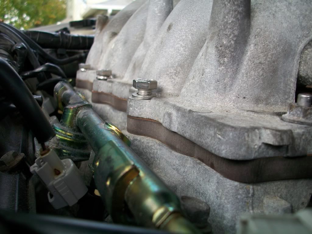
Remove the upper intake manifold. Once the manifold has been removed it will look like the picture shown below:

Click the image to open in full size.

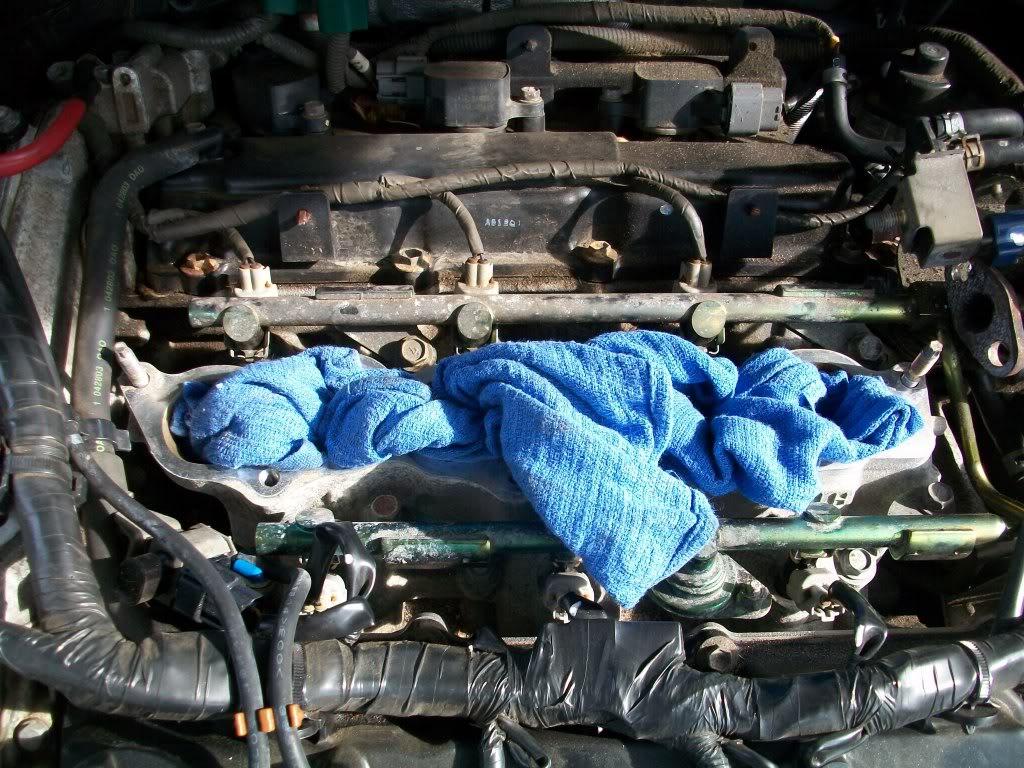
STOP EVERYTHING! PLACE RAGS INTO THE CHAMBERS.

Click the image to open in full size.

If a bolt is dropped into there you have big problems.

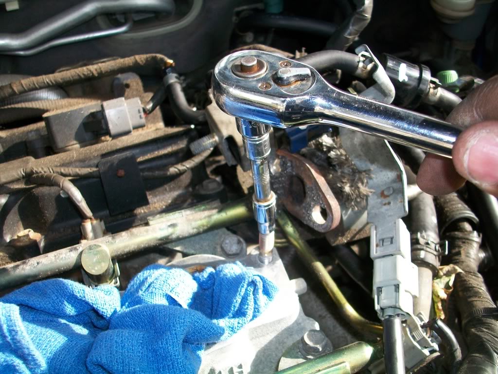
Using a 6mm socket , remove the intake studs on both sides

Click the image to open in full size.

Using a 3mm allen head bit install the new intake studs provided with the kit

Click the image to open in full size.

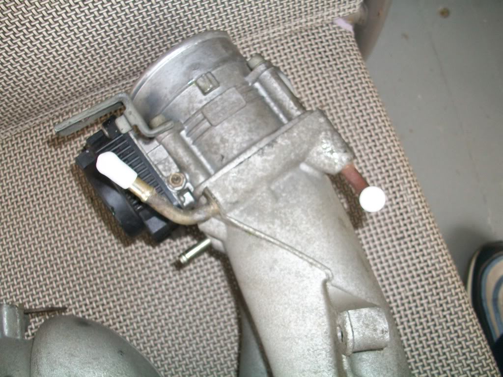
Proceed to the two hoses that were removed from the throttle body. using the brass hose mender join the hoses as shown to perform a throttle body bypass. this will help in removing unwanted heat produced from the hot coolant out of the throttle body

Click the image to open in full size.

Click the image to open in full size.

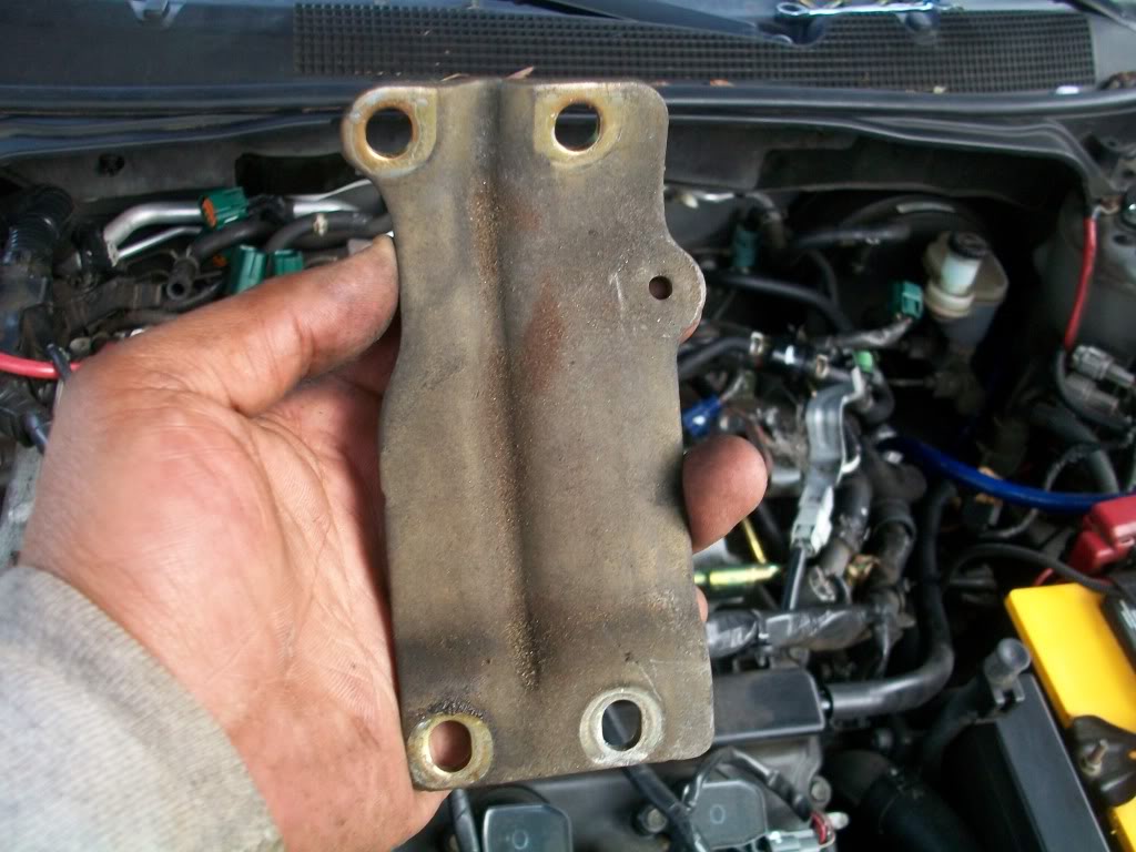
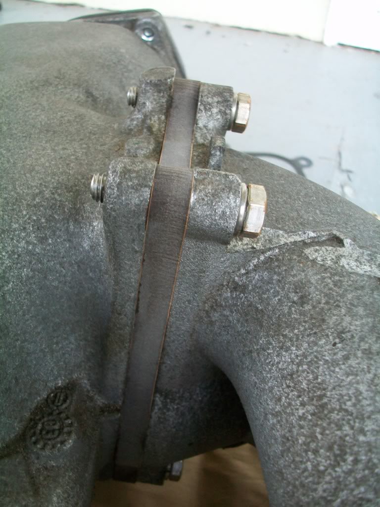
Due to the increase width from the spacers the rear manifold stay bracket must be removed using a 12mm socket and ratchet

Click the image to open in full size.

Click the image to open in full size.

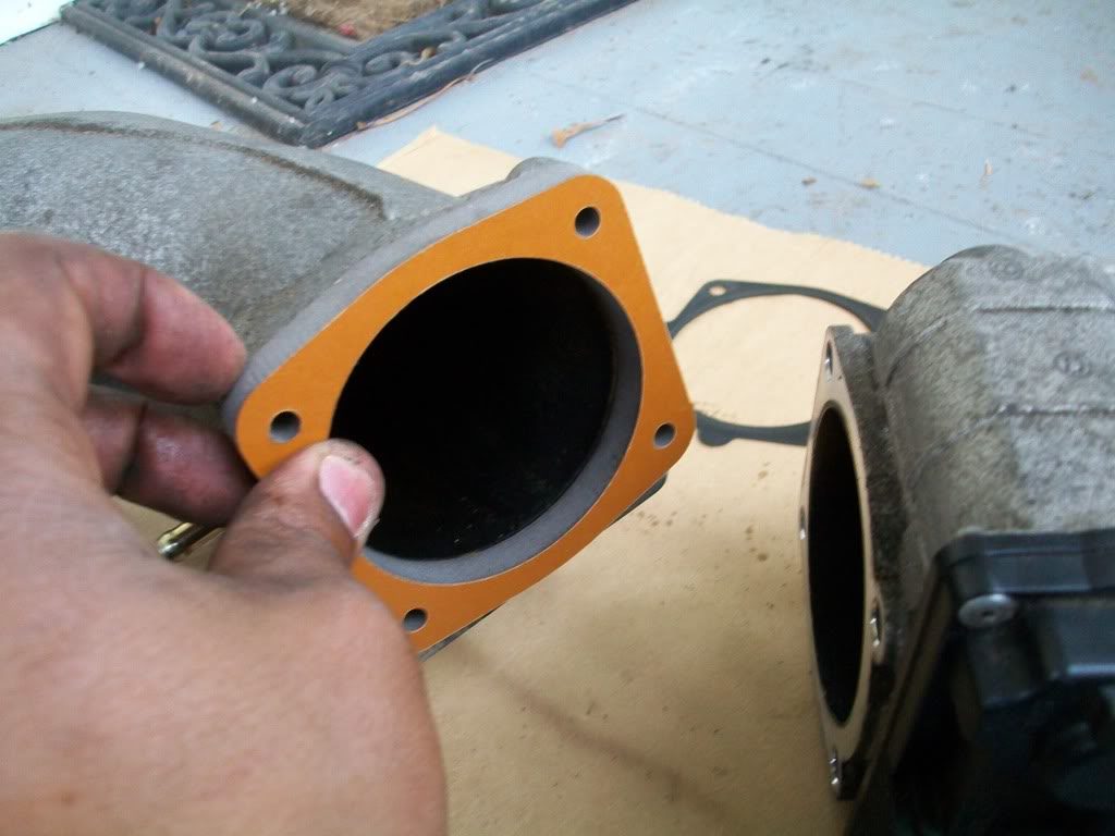
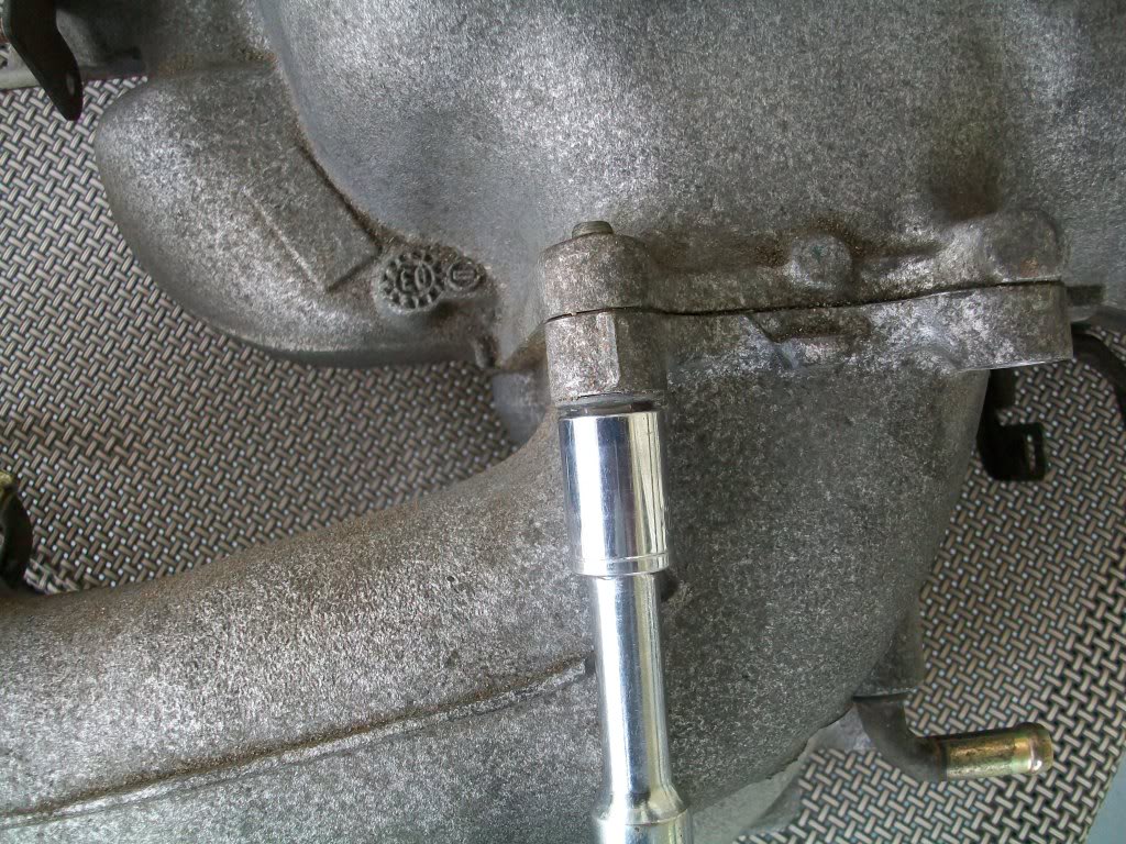
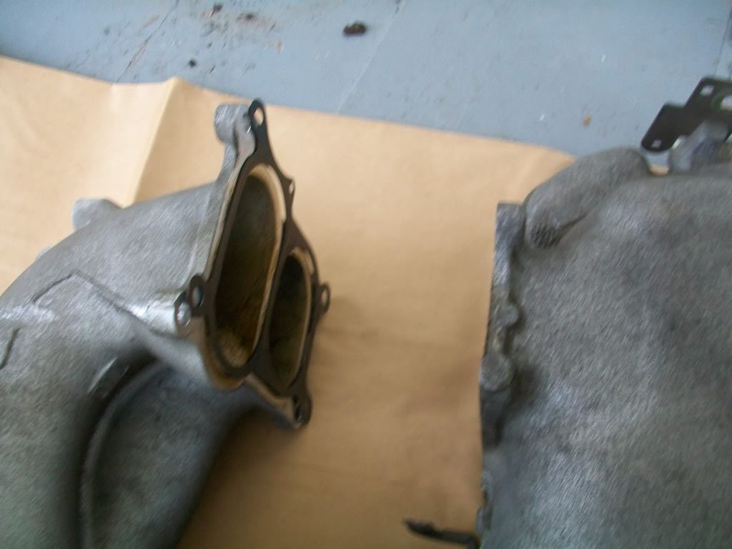
Using a 12mm socket remove elbow and stock gasket from the manifold

Click the image to open in full size.

Click the image to open in full size.

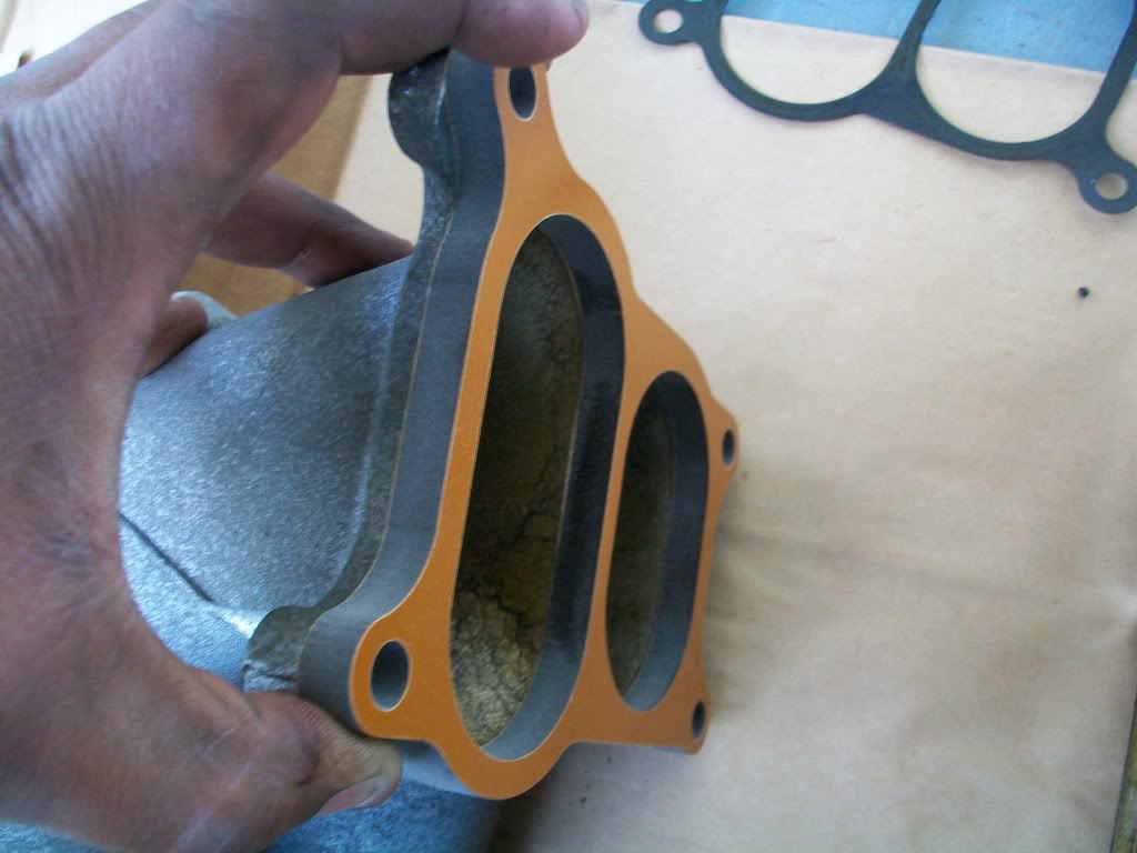
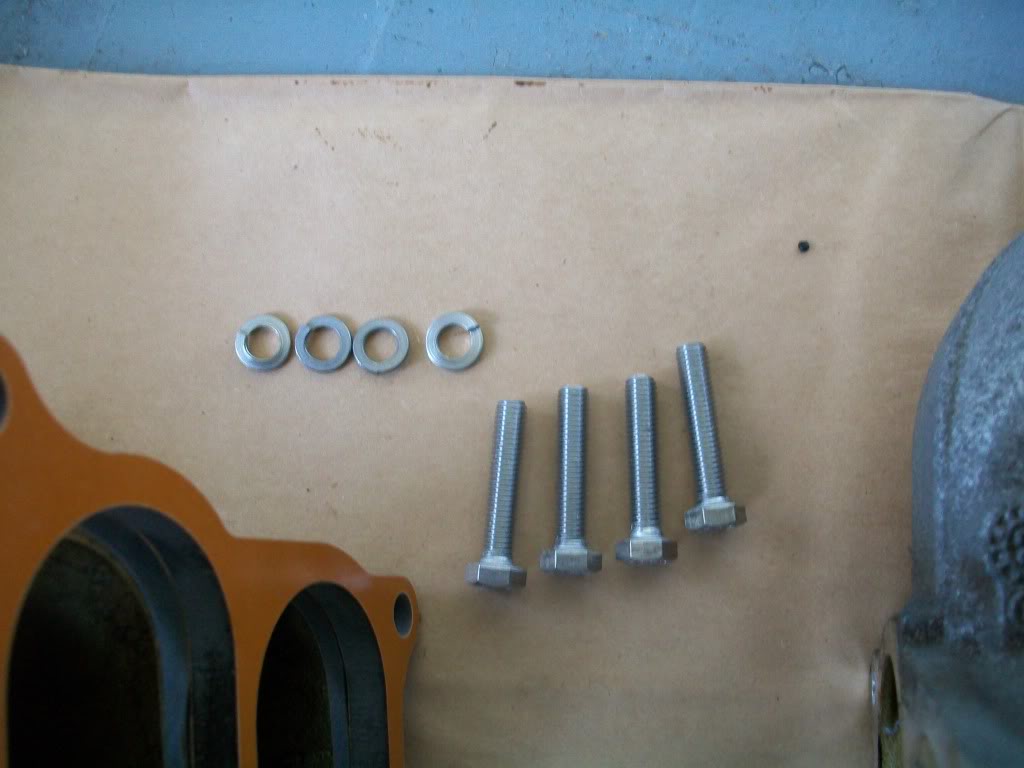
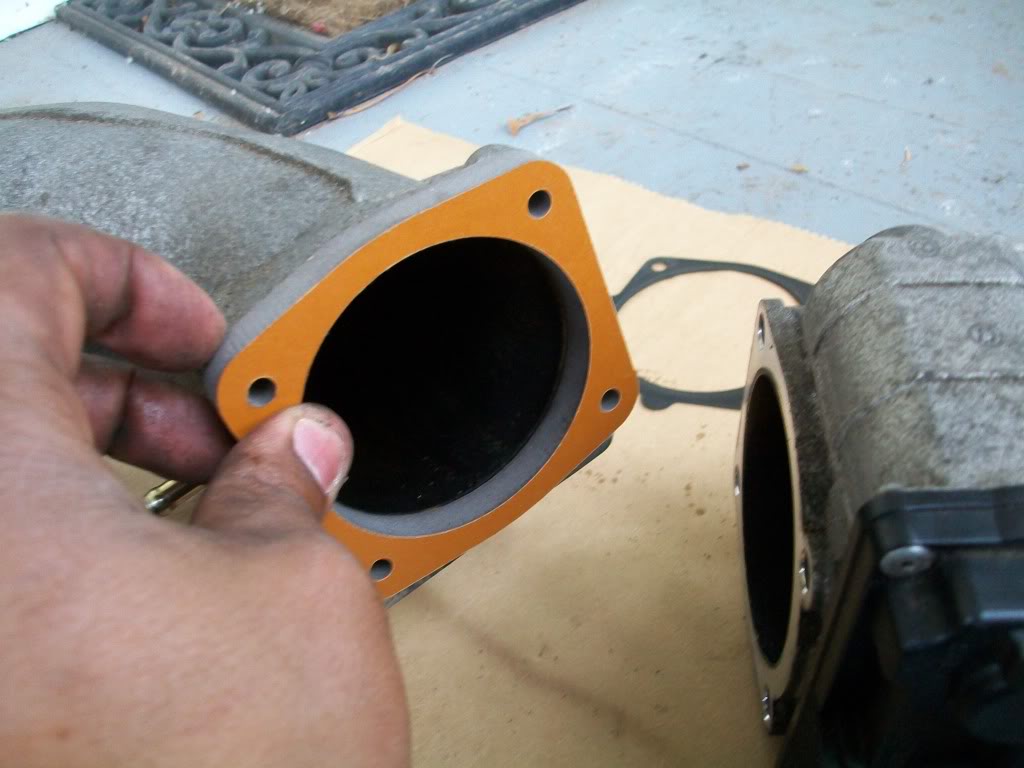
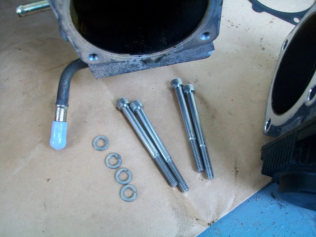
Apply the thickness of a nickle coin of rtv gasket maker to both sides of the elbow spacer and reinstall using the 4 hex head bolts and lock washers provided in the kit.

Click the image to open in full size.

Click the image to open in full size.

Click the image to open in full size.

Move on to the throttle body spacer

Using the white caps provided in the kit , cap off the 2 metal pipes going into the throttle body as shown

Click the image to open in full size.

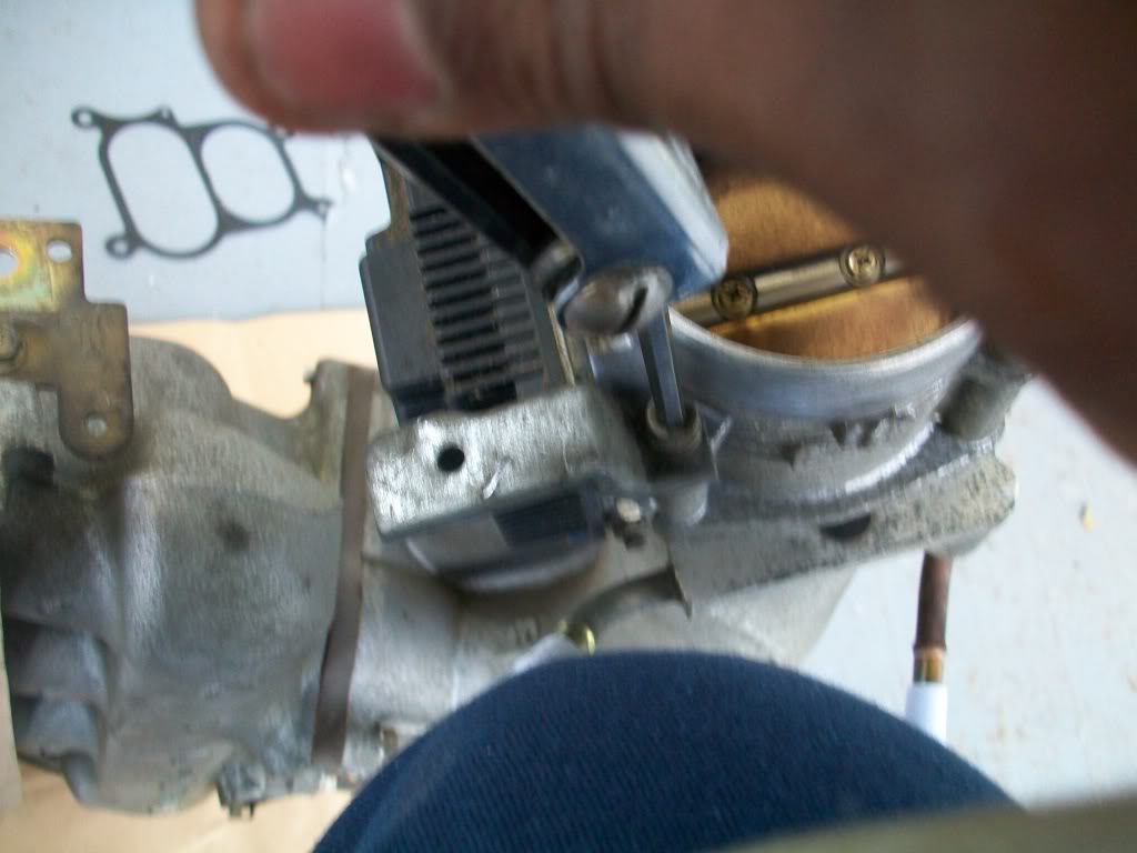
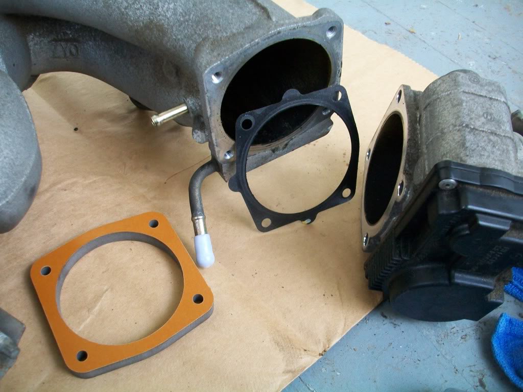
Using a 5mm allen head bit , remove the throttle body from the elbow. do not touch the valves on the throttle body. this will cause a idle malfunction and check engine light that can only resetted by the nissan dealership.

Click the image to open in full size.

Click the image to open in full size.

Click the image to open in full size.

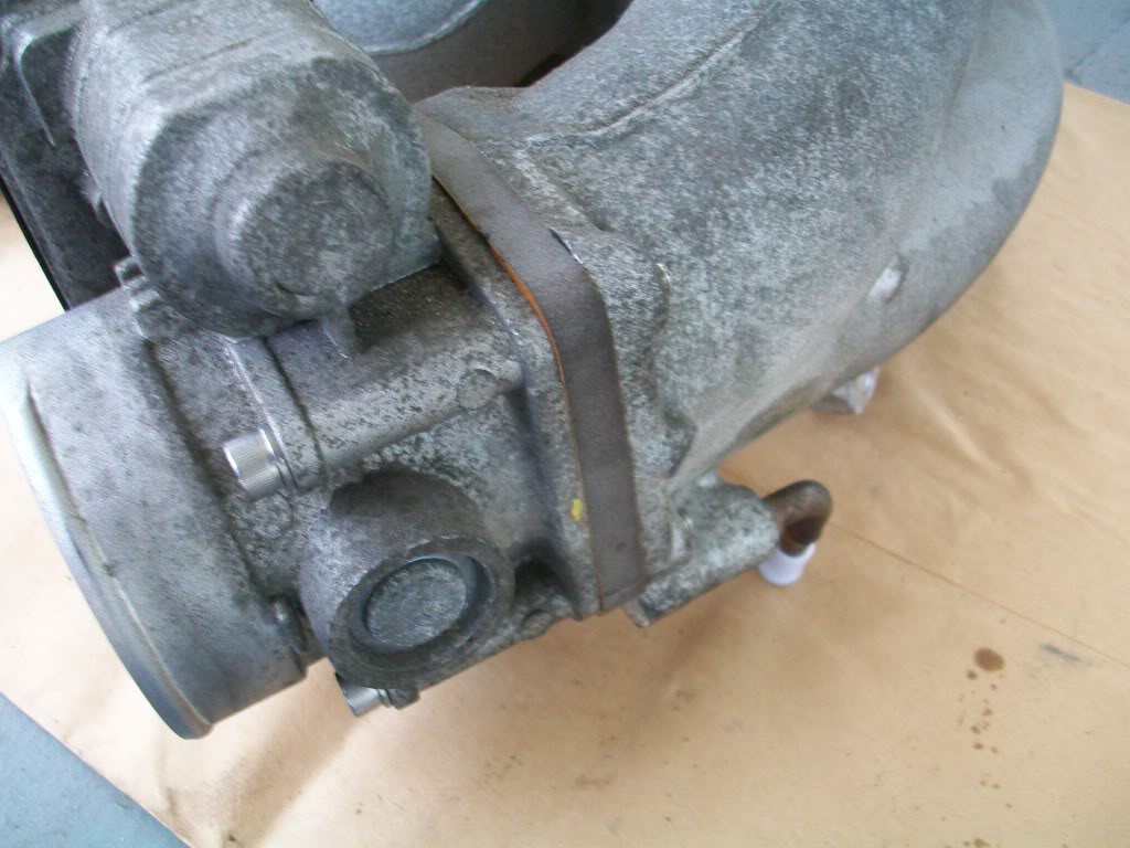
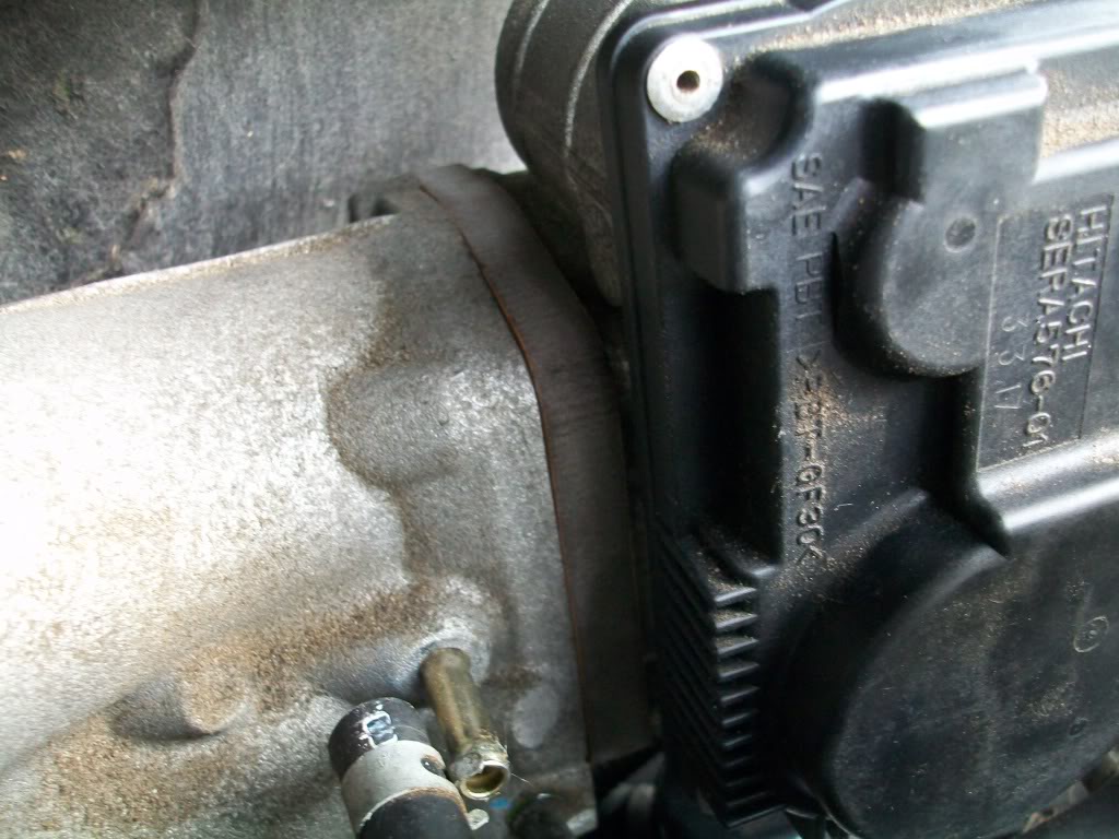
Remove OEM gasket and apply the RTV gasket maker to both sides of the throttle body spacer. reinstall using the allen head bolts and lock washer as shown. remember the location of the bracket that was removed from the throttle body

Click the image to open in full size.

Click the image to open in full size.

Onto the main manifold spacer

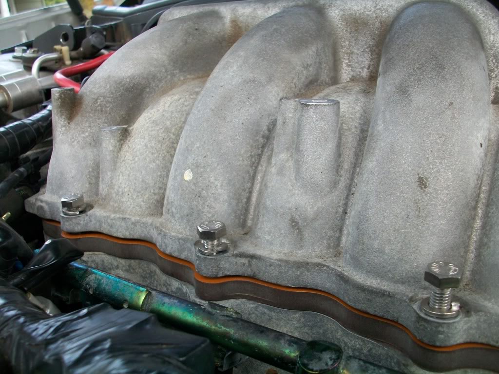
Apply RTV gasket maker to both sides of the spacer and center the manifold onto it. the intake studs will guide you. using the 3 hex bolts and lock washers tighten the manifold.

Click the image to open in full size.

Click the image to open in full size.

Reuse the oem intake stud nut and apply them onto the new intake studs on both sides

Click the image to open in full size.

Check that everything looks as shown

Click the image to open in full size.

Click the image to open in full size.

Click the image to open in full size.

Wait 45 mins for the RTV gasket maker to set.

Reconnect all the hardware and connectors that was removed to uninstall the upper manifold.

Reconnect the battery.

Peform an ECU Reset by following these steps

1. Turn ignition switch on and wait about 3 seconds.

Repeat the following steps (2a and 2b) procedures quickly five times within 5 seconds.

2a. Fully depress the accelerator pedal (HARD).
2b. Fully release the accelerator pedal.

3. Wait 7 seconds, fully depress the accelerator pedal and keep it for approx. 10 seconds until the CEL starts blinking. (here is where i think you can get a code from this.)
4. Fully release the accelerator pedal (while the CEL is still blinking)
5. Wait about 10 second.
6. Fully depress the accelerator pedal and keep it for more than 10 seconds.
7. Fully release the accelerator pedal
8. Turn ignition switch to “OFF” position and now you can start the car.

Perform an idle relearn by follwing these steps

Make sure that accelerator pedal is fully released.
Turn ignition switch ‘ON’ and wait at least 2 seconds.
Turn ignition switch ‘OFF’ wait at least 10 seconds.
Turn ignition switch ‘ON’ and wait at least 2 seconds.
Turn ignition switch ‘OFF’ wait at least 10 seconds.
Perform “Throttle Valve Closed Position Learning” .
Make sure that accelerator pedal is fully released.
Turn ignition switch ‘ON’.
Turn ignition switch ‘OFF’ wait at least 10 seconds.
Make sure that throttle valve moves during above 10 seconds by confirming the operating sound.
Start engine and warm it up to normal operating temperature.
Turn ignition switch ‘OFF’ and wait at least 10 seconds.
Confirm that accelerator pedal is fully released, turn ignition switch ‘ON’ and wait 3 seconds.
Repeat the following procedure quickly five times within 5 seconds.
Fully depress the accelerator pedal.
Fully release the accelerator pedal.
Wait 7 seconds, fully depress the accelerator pedal and keep it for approx. 20 seconds until the MIL stops blinking and turned ON.
Fully release the accelerator pedal within 3 seconds after the MIL goes off.
Start engine and let it idle.
Wait 20 seconds.
Rev up the engine two or three times and make sure that idle speed and ignition timing are within the specifications.
If idle speed and ignition timing are not within the specification, the result will be incomplete.

Enjoy

Cory

Loading