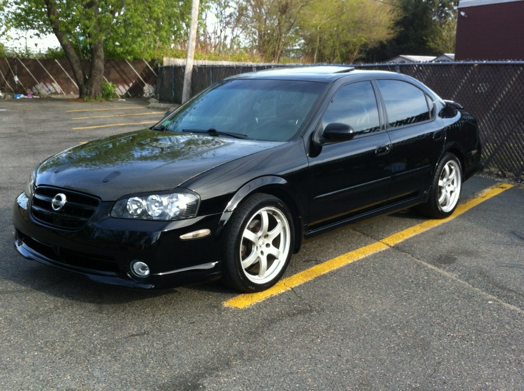
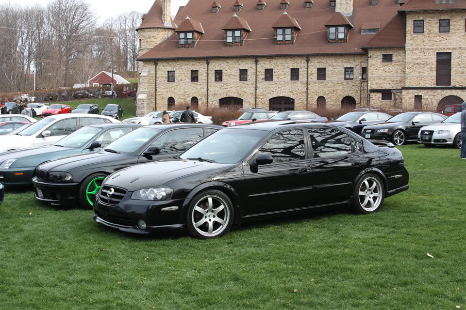
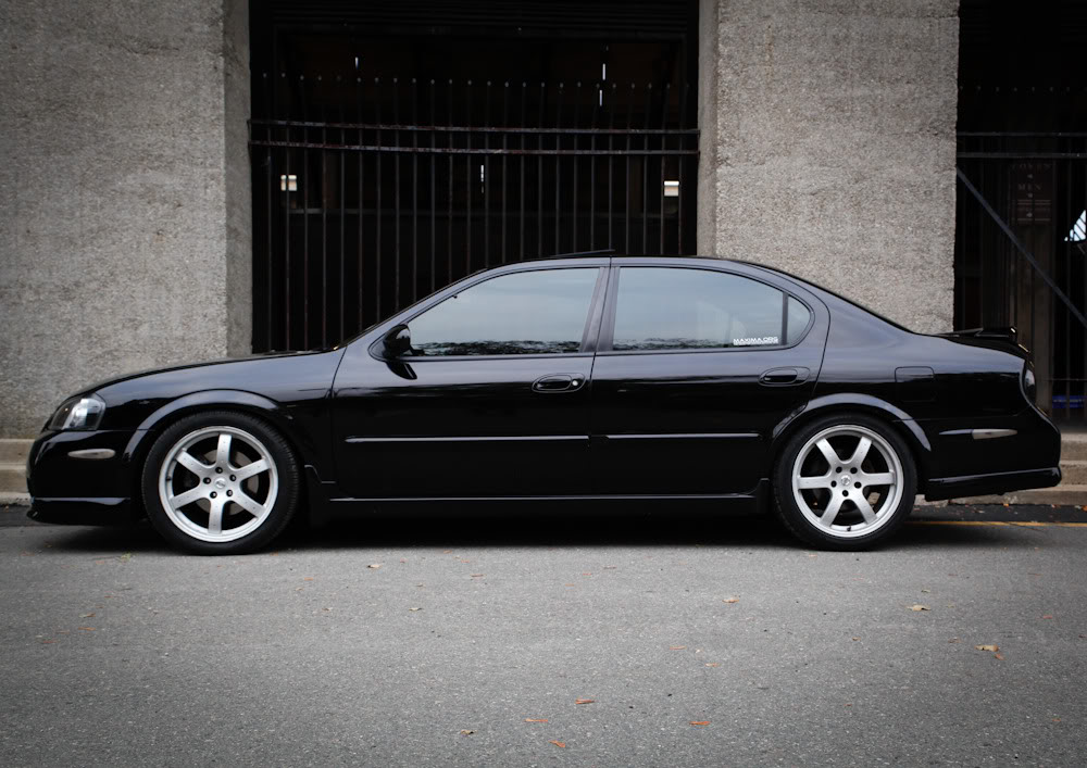
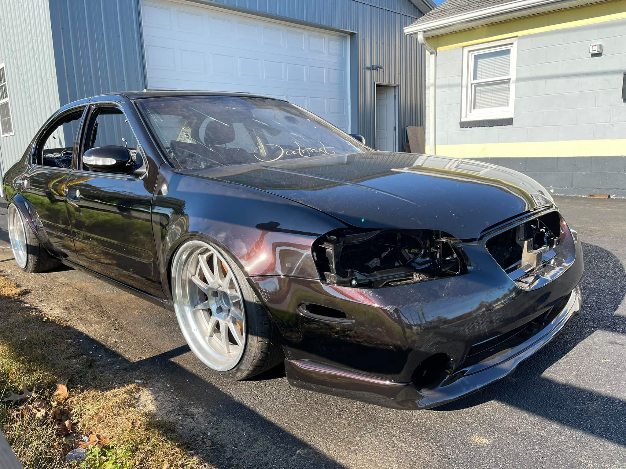
Owner: zero2sixtyZ aka Zeead R.
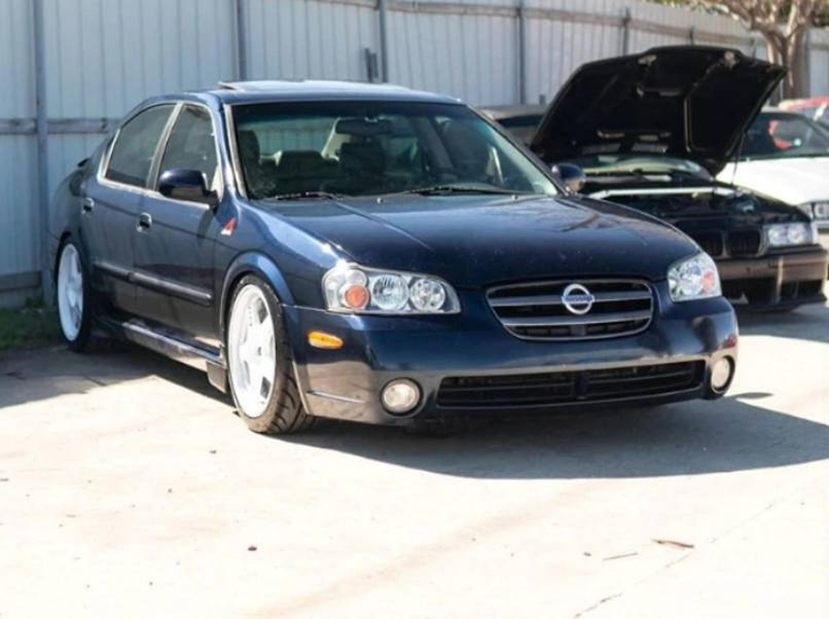
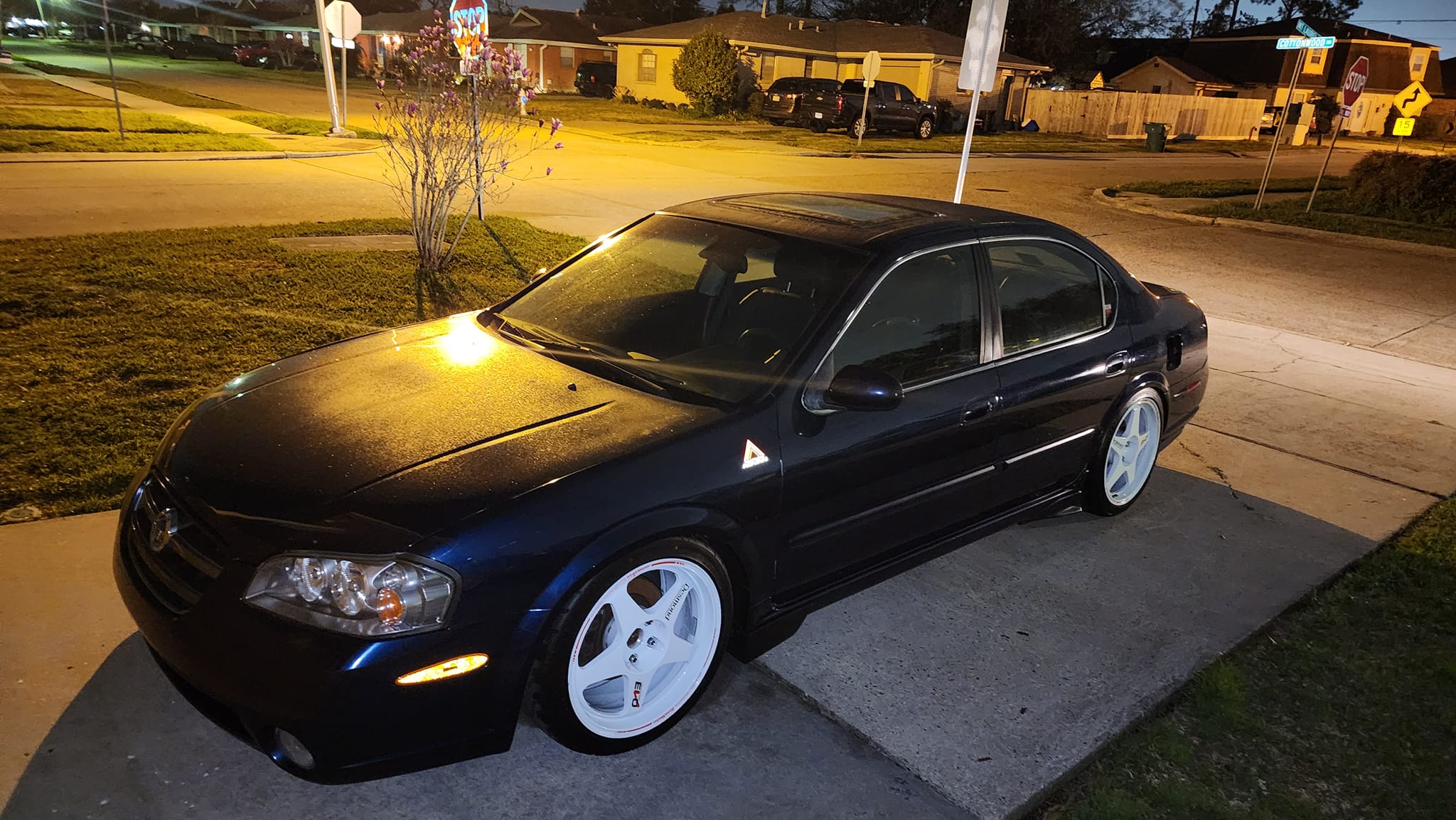
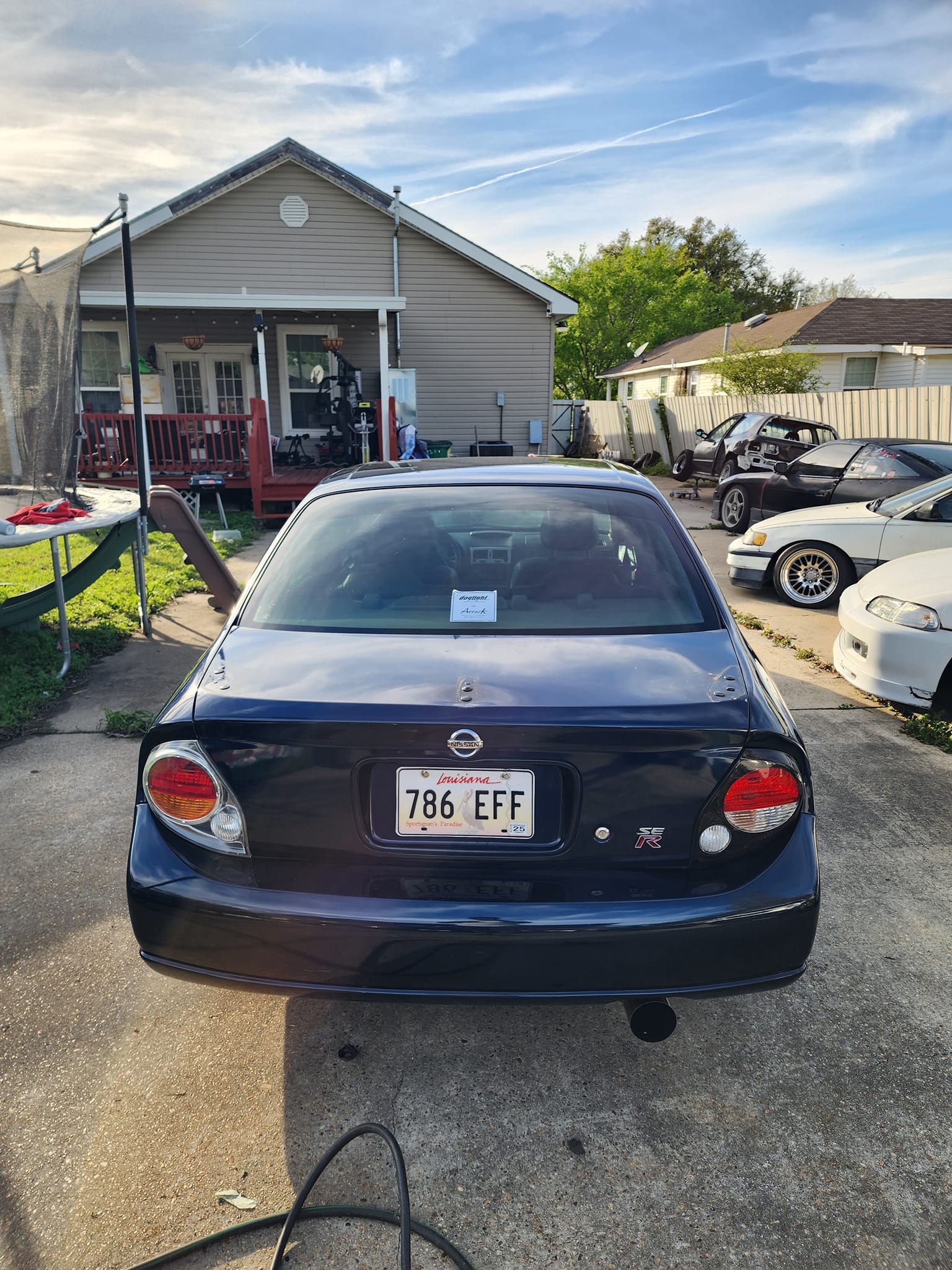
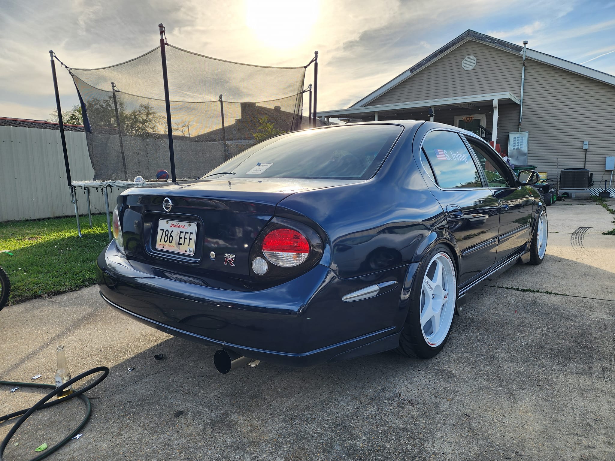
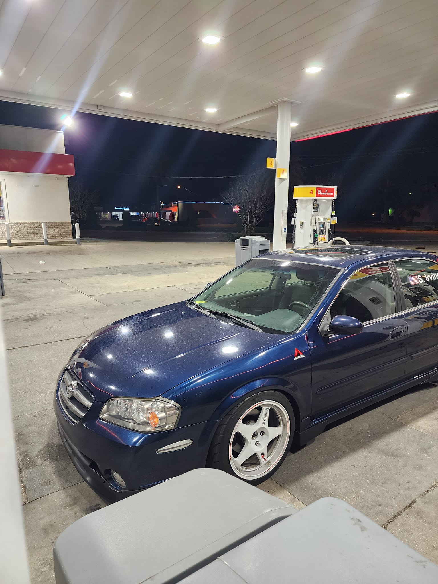
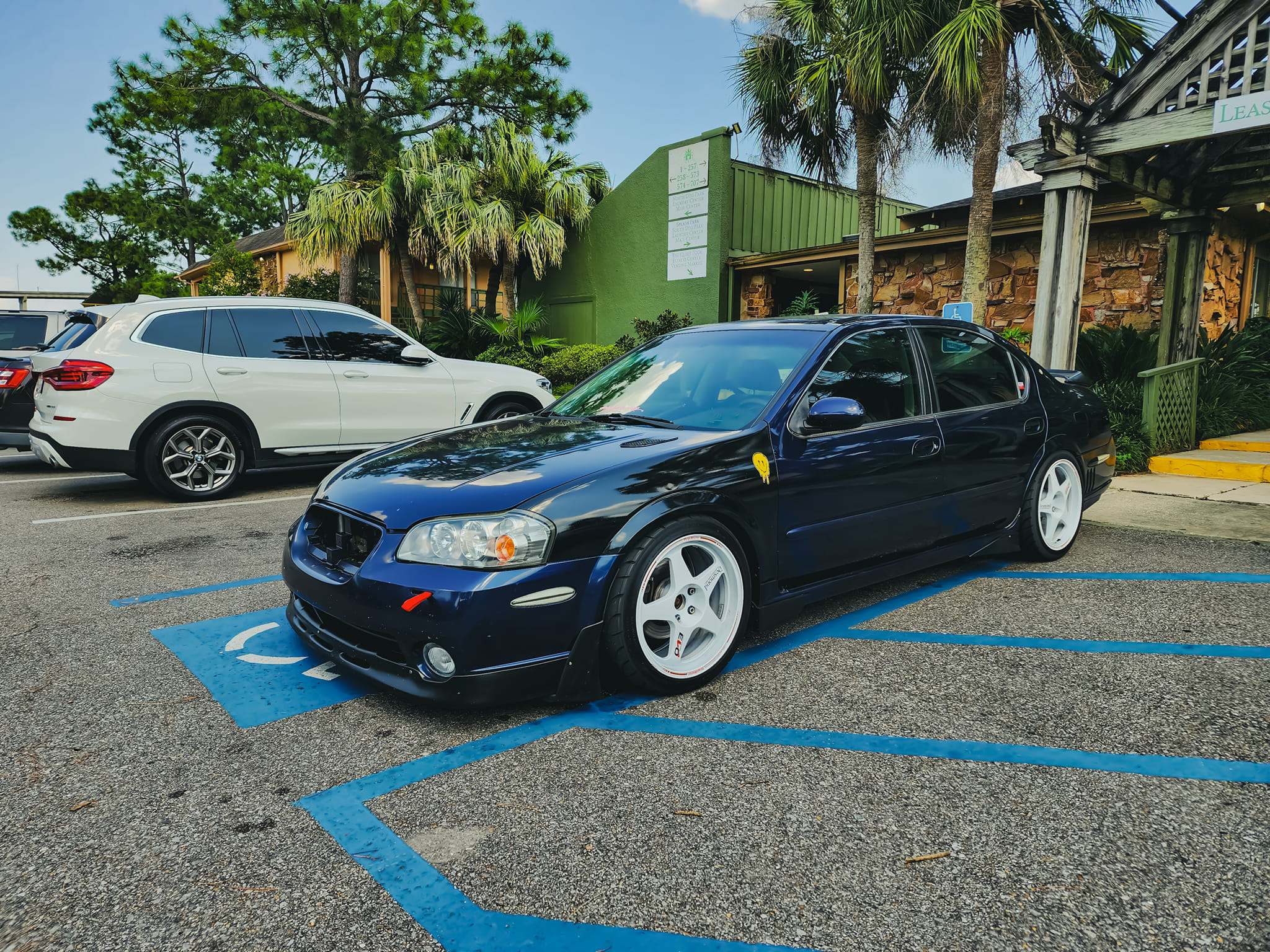
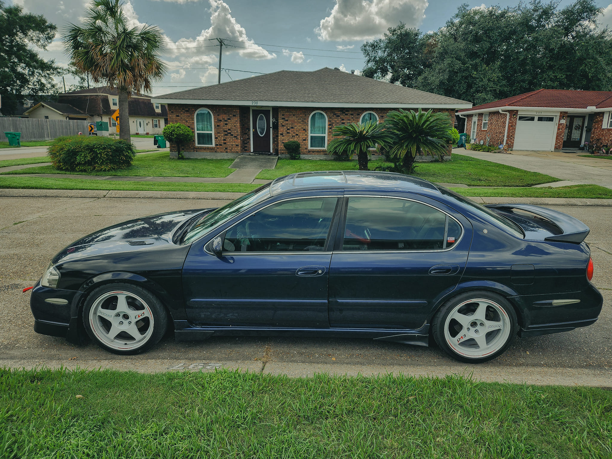
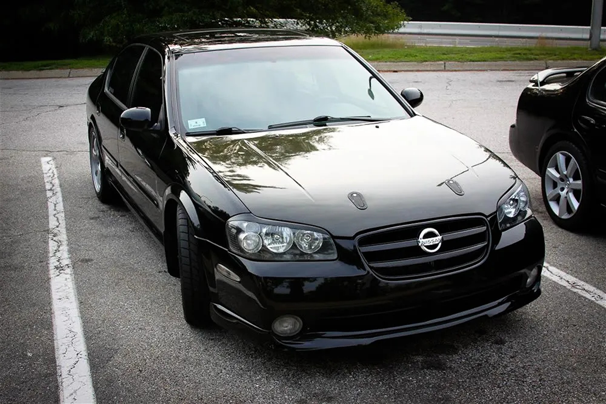
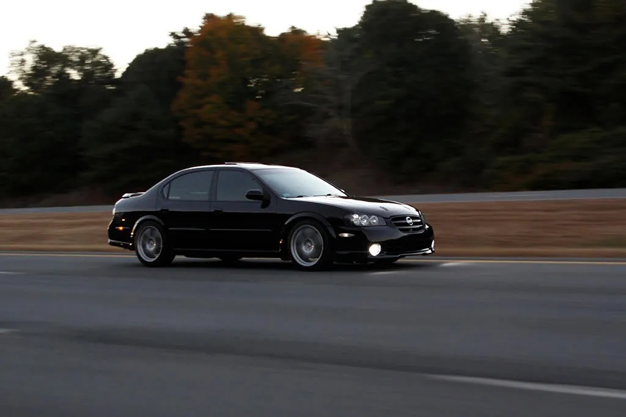
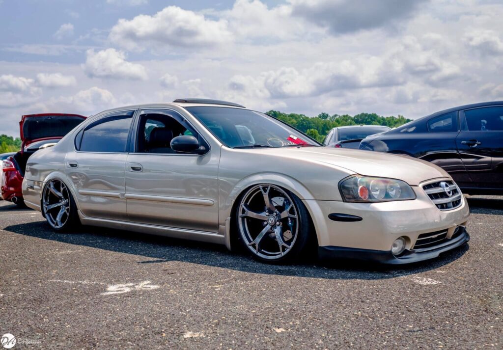
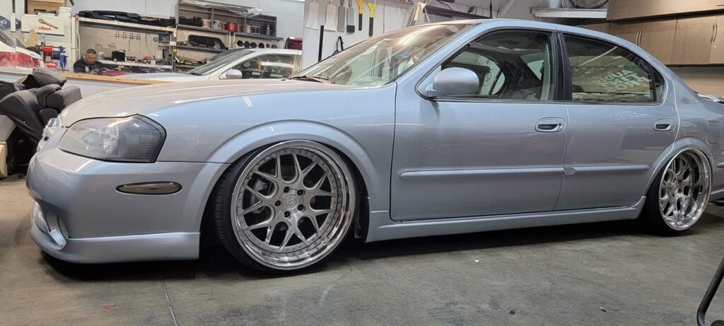
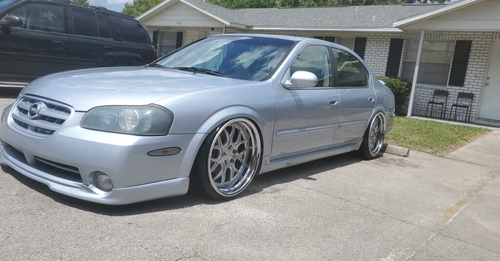
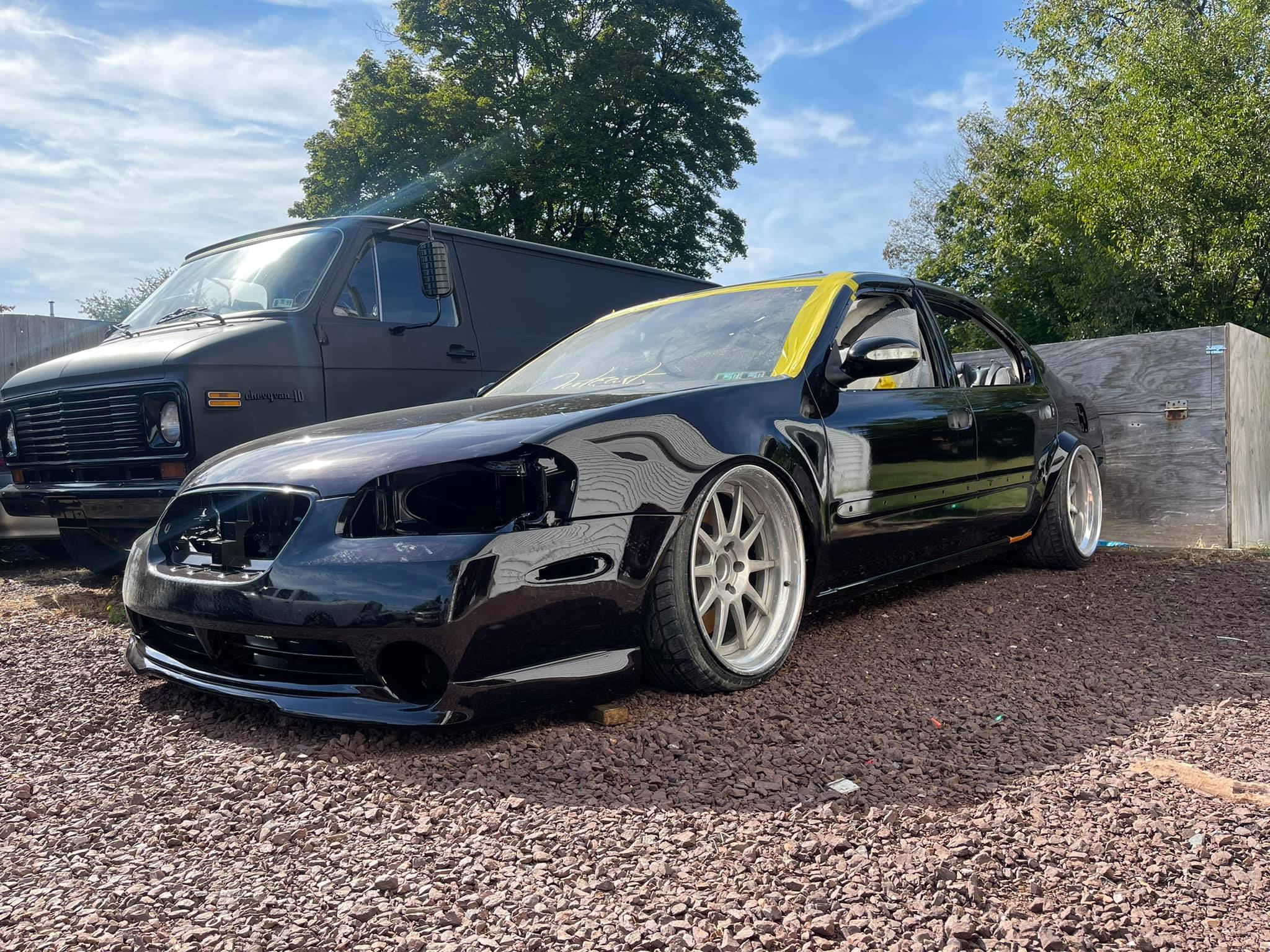
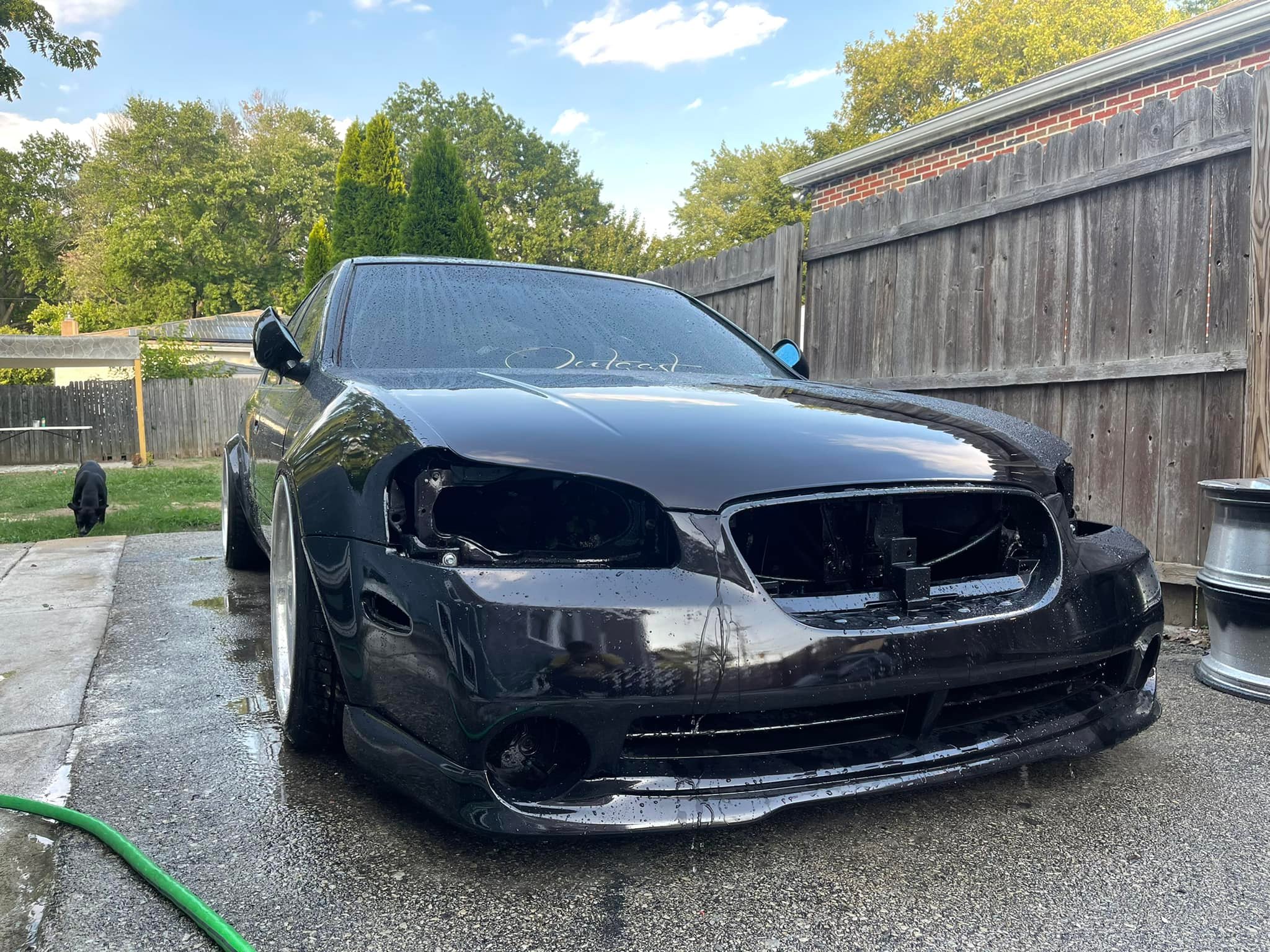
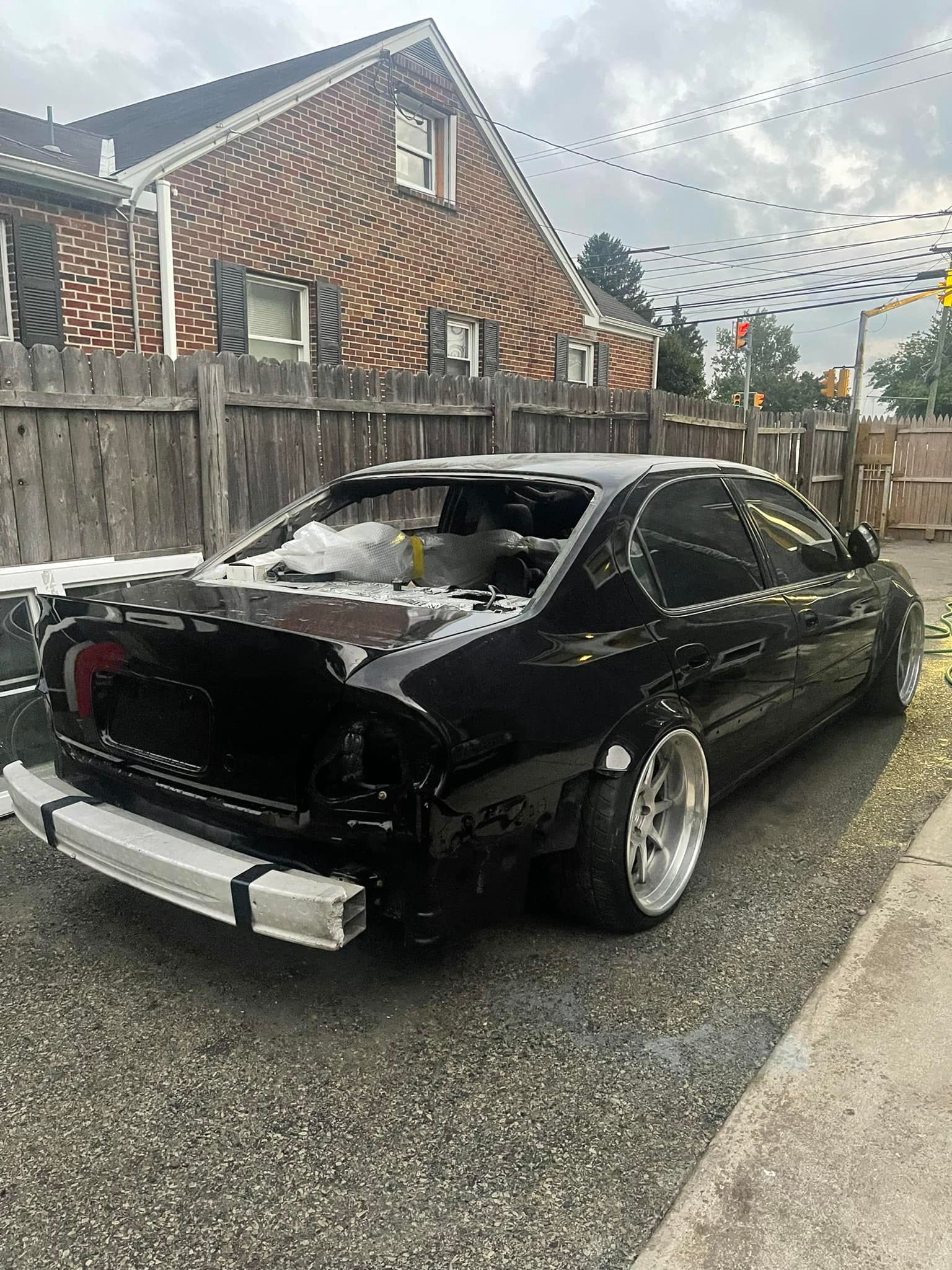
Year: 2002
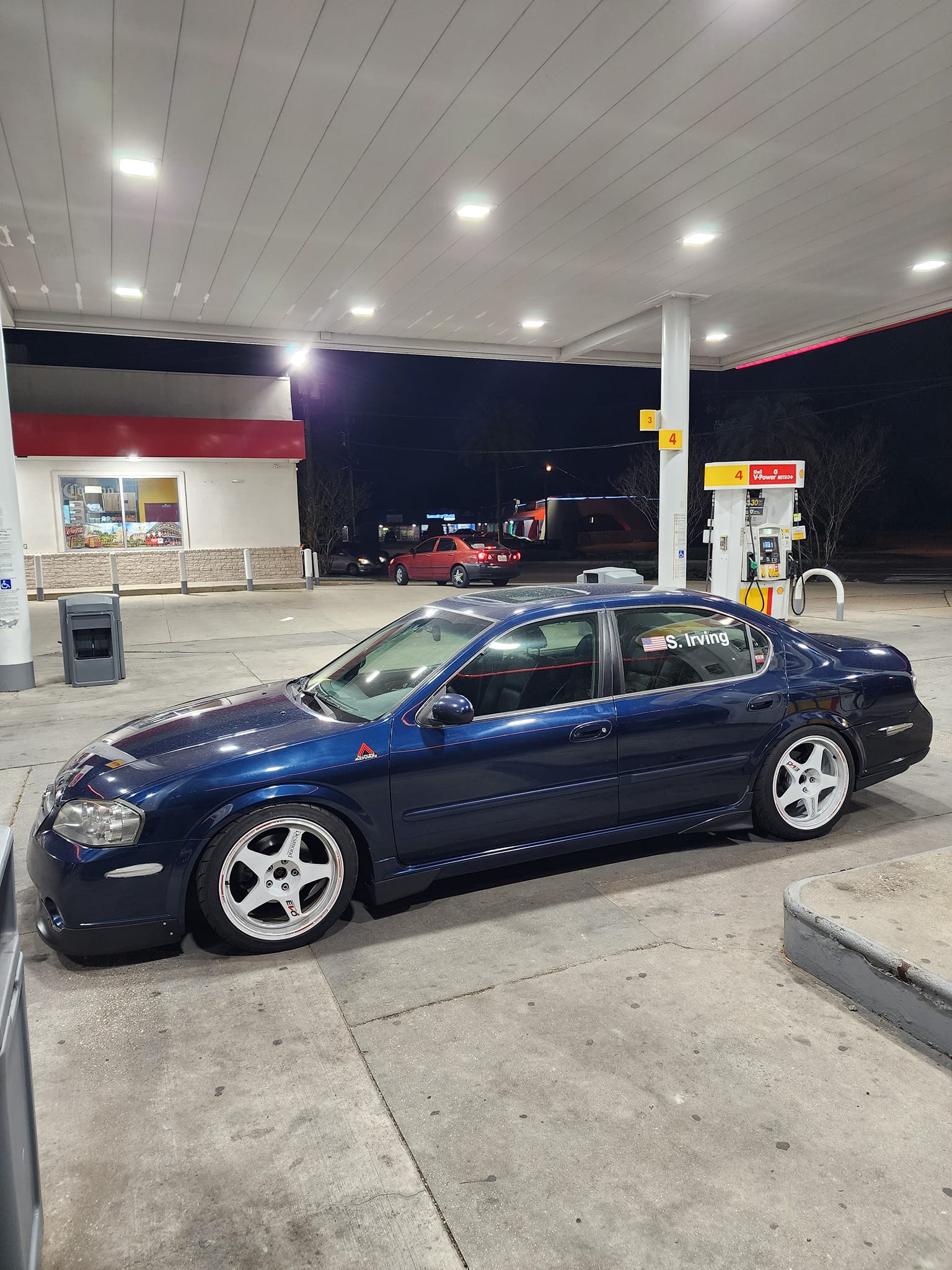
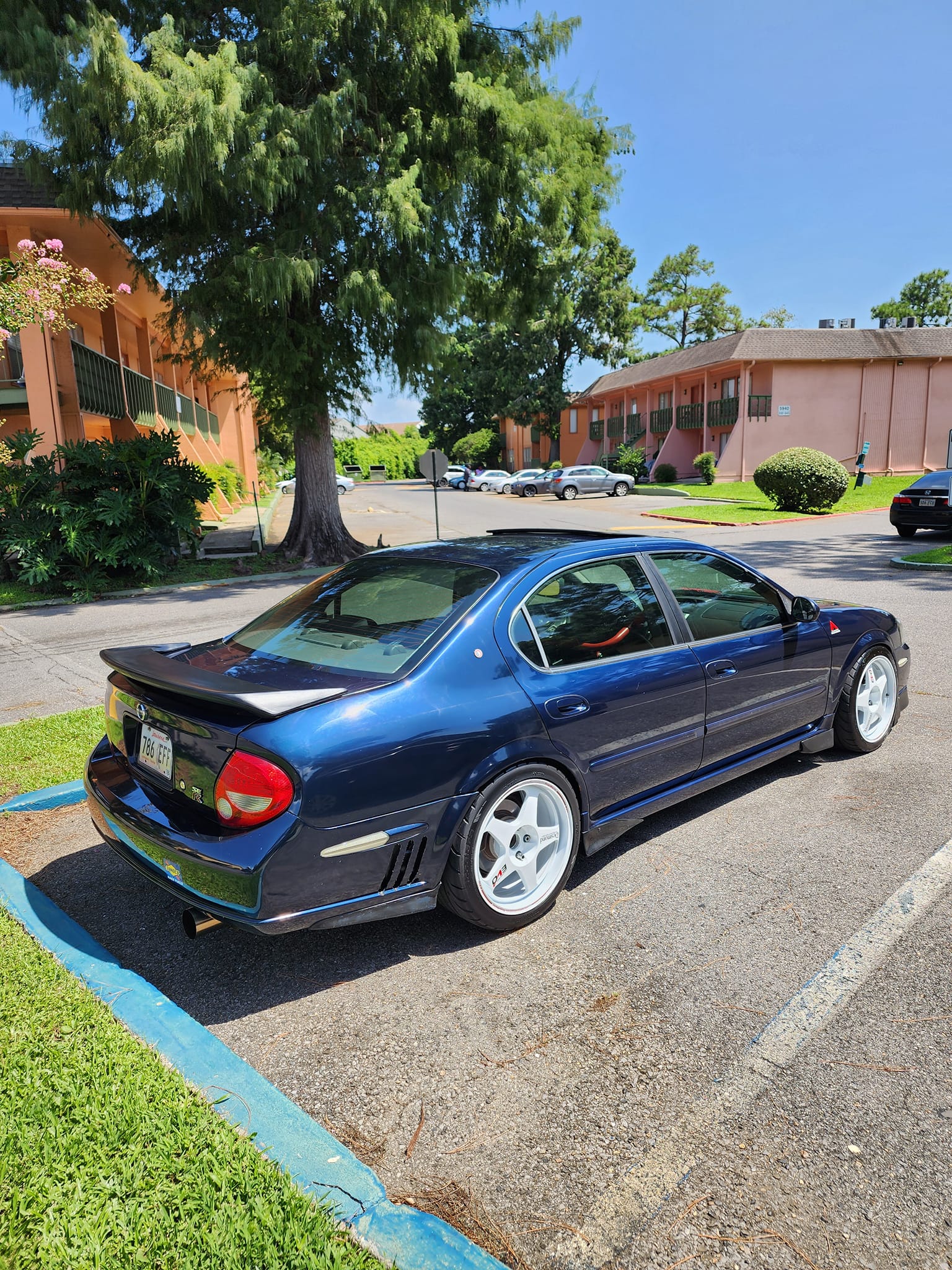
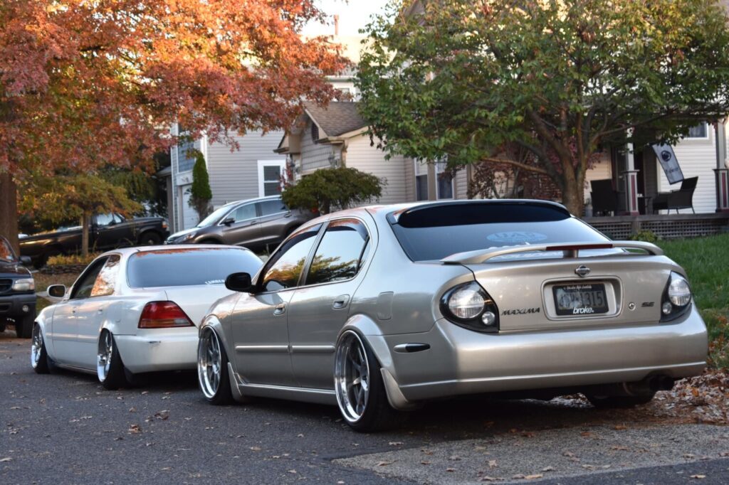
Model: Maxima
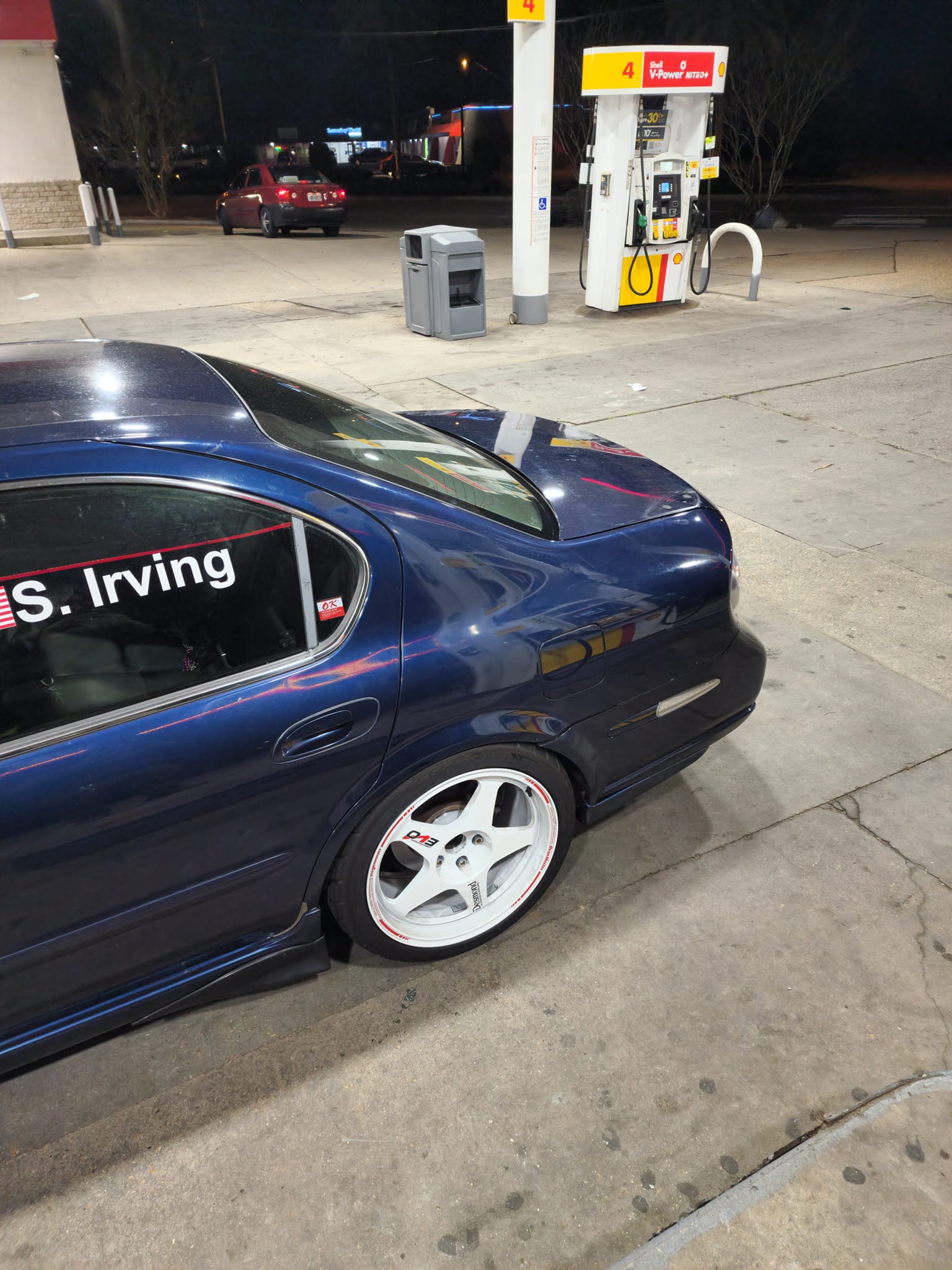
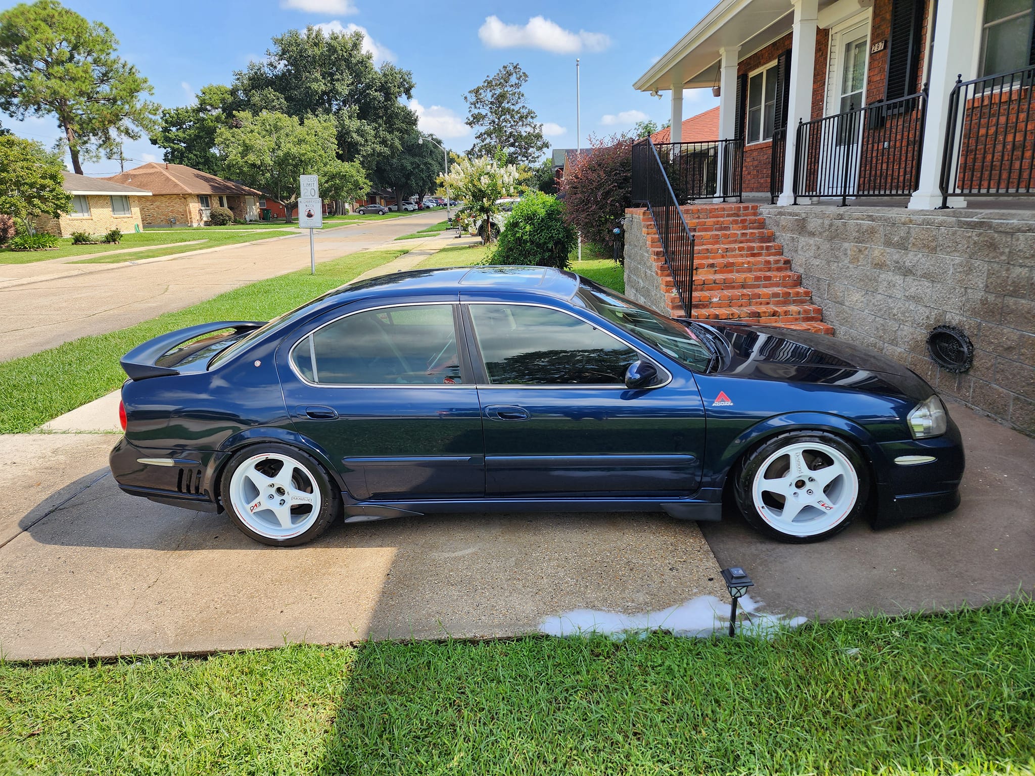
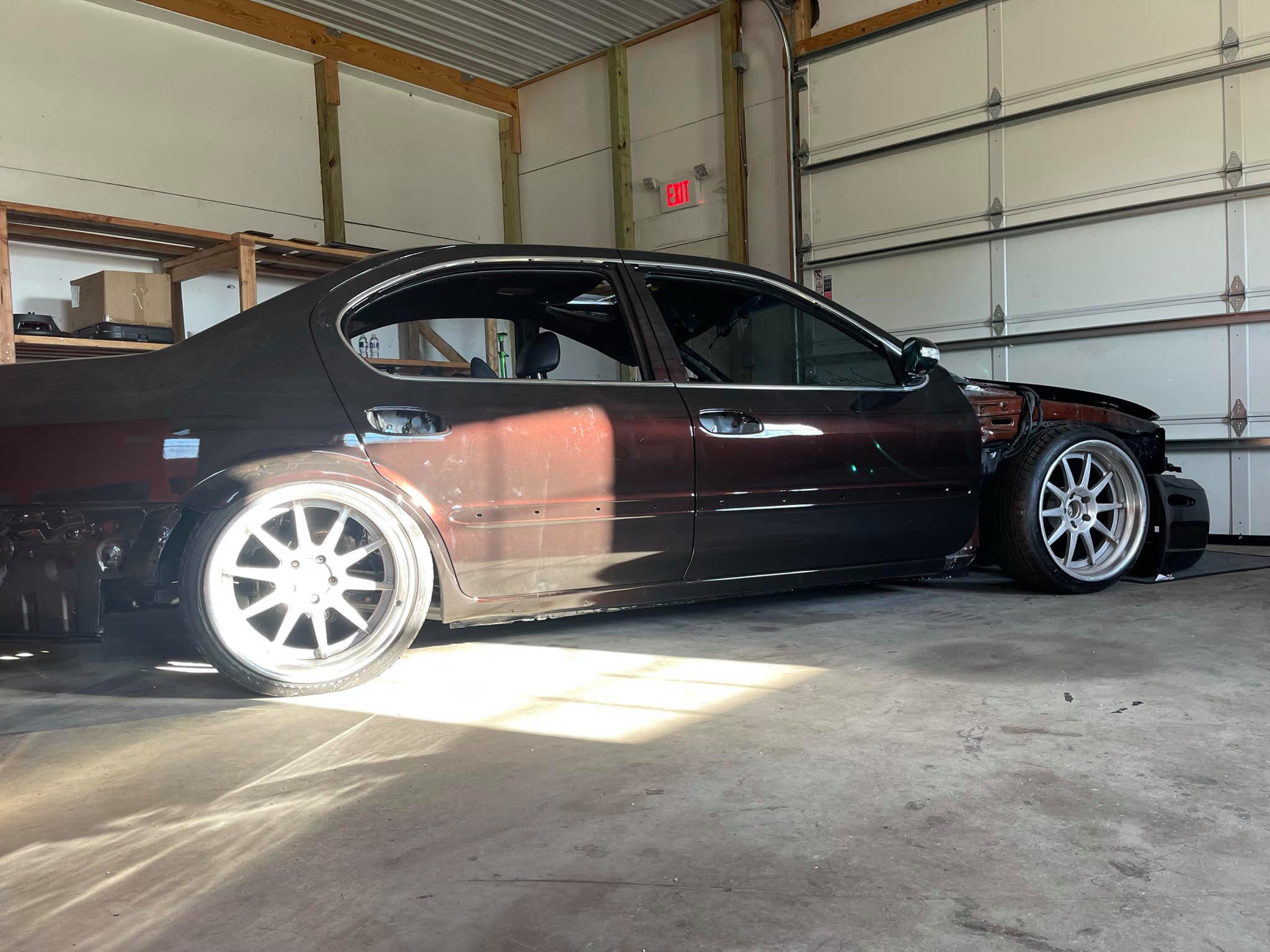
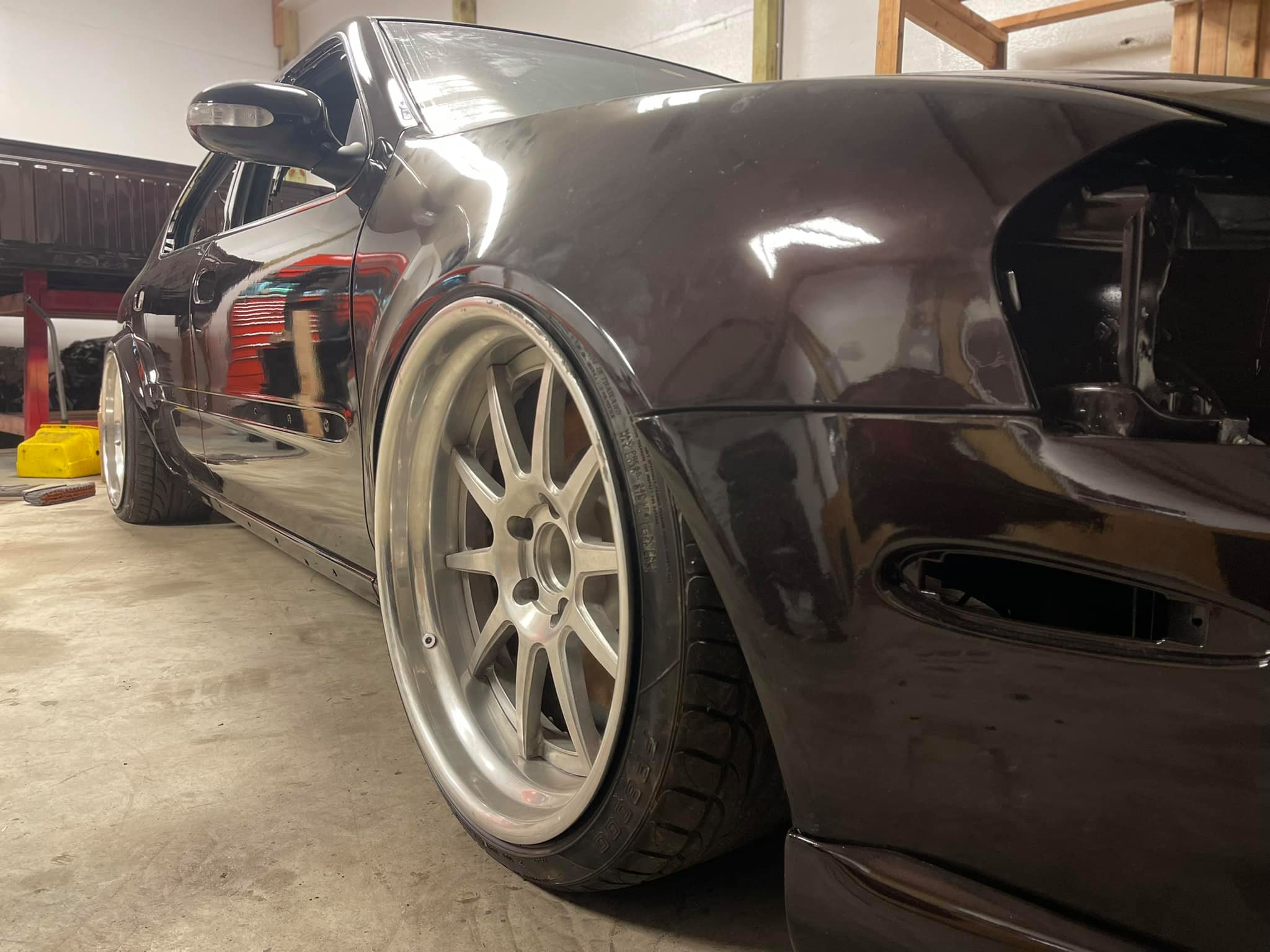
Color: Black
Engine: VQ35DE
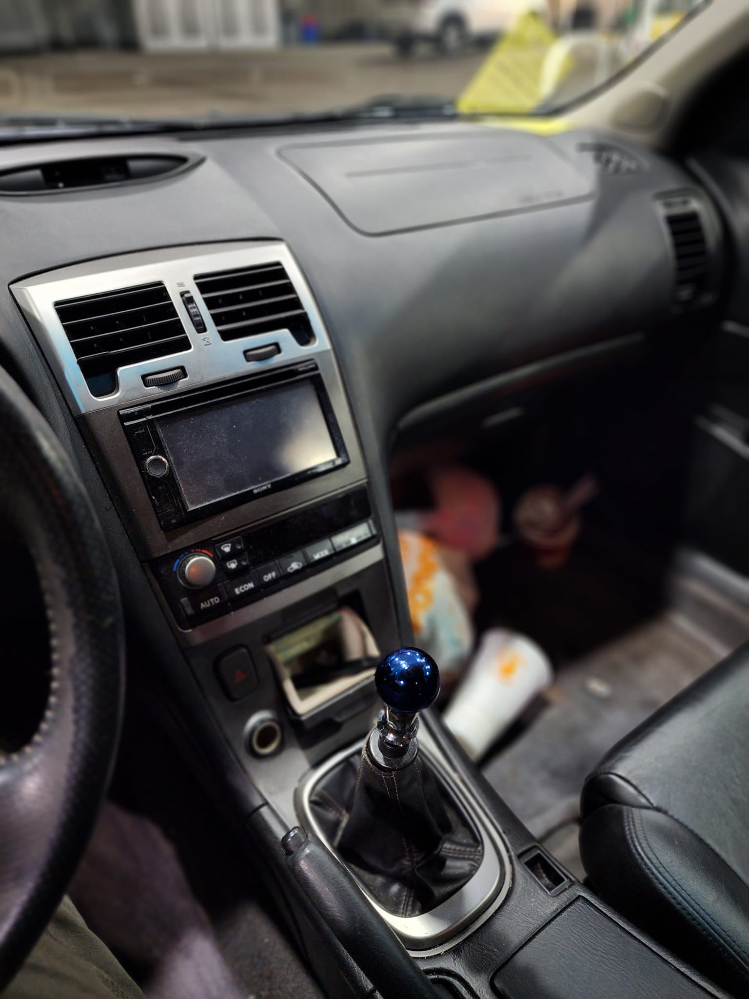
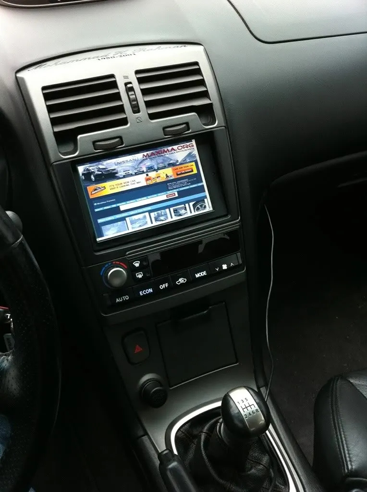
Transmission: 6-Speed Manual
Trim: SE

Mod List:
Exterior:
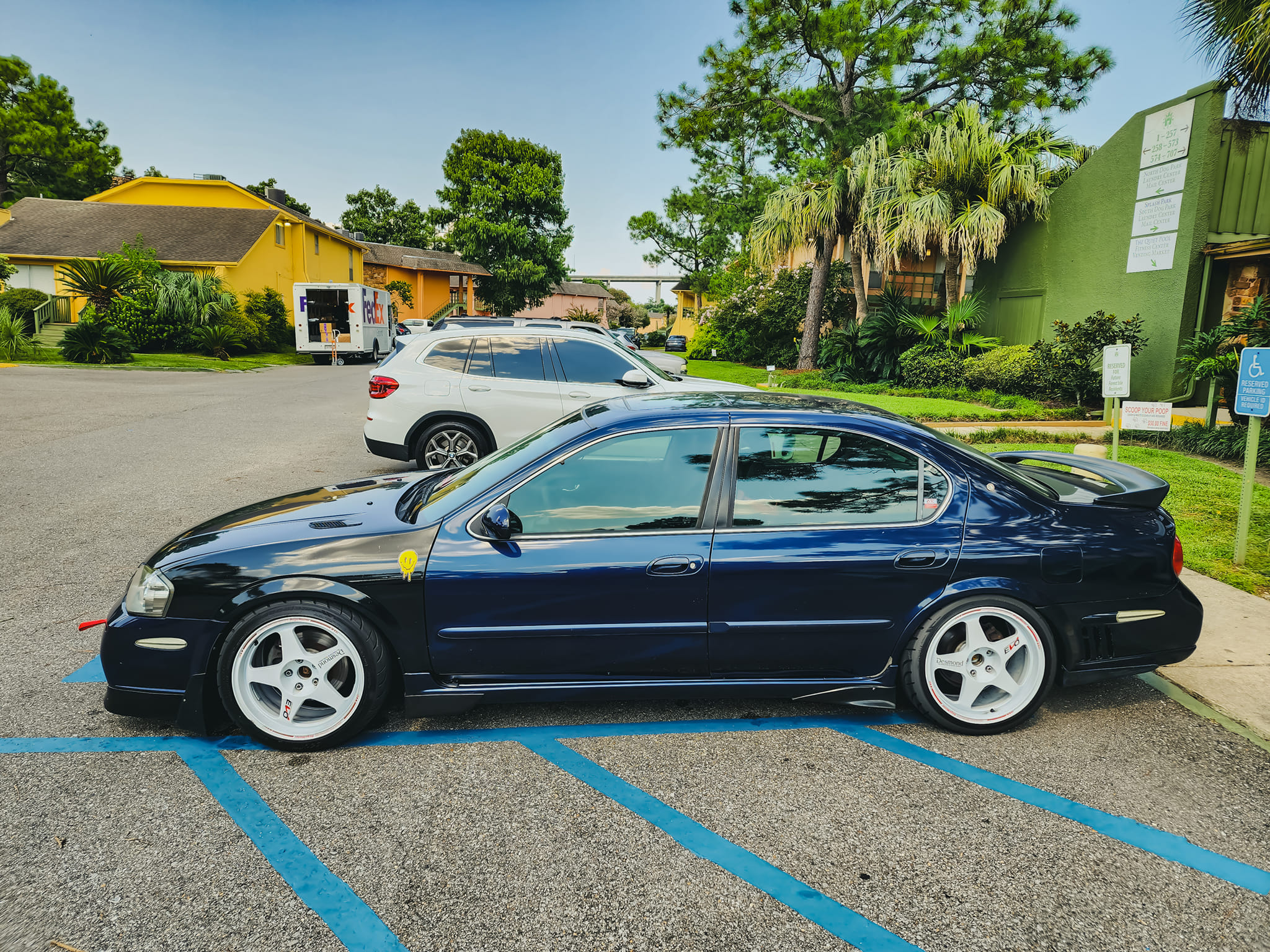
– 35% Suntek Window Tint
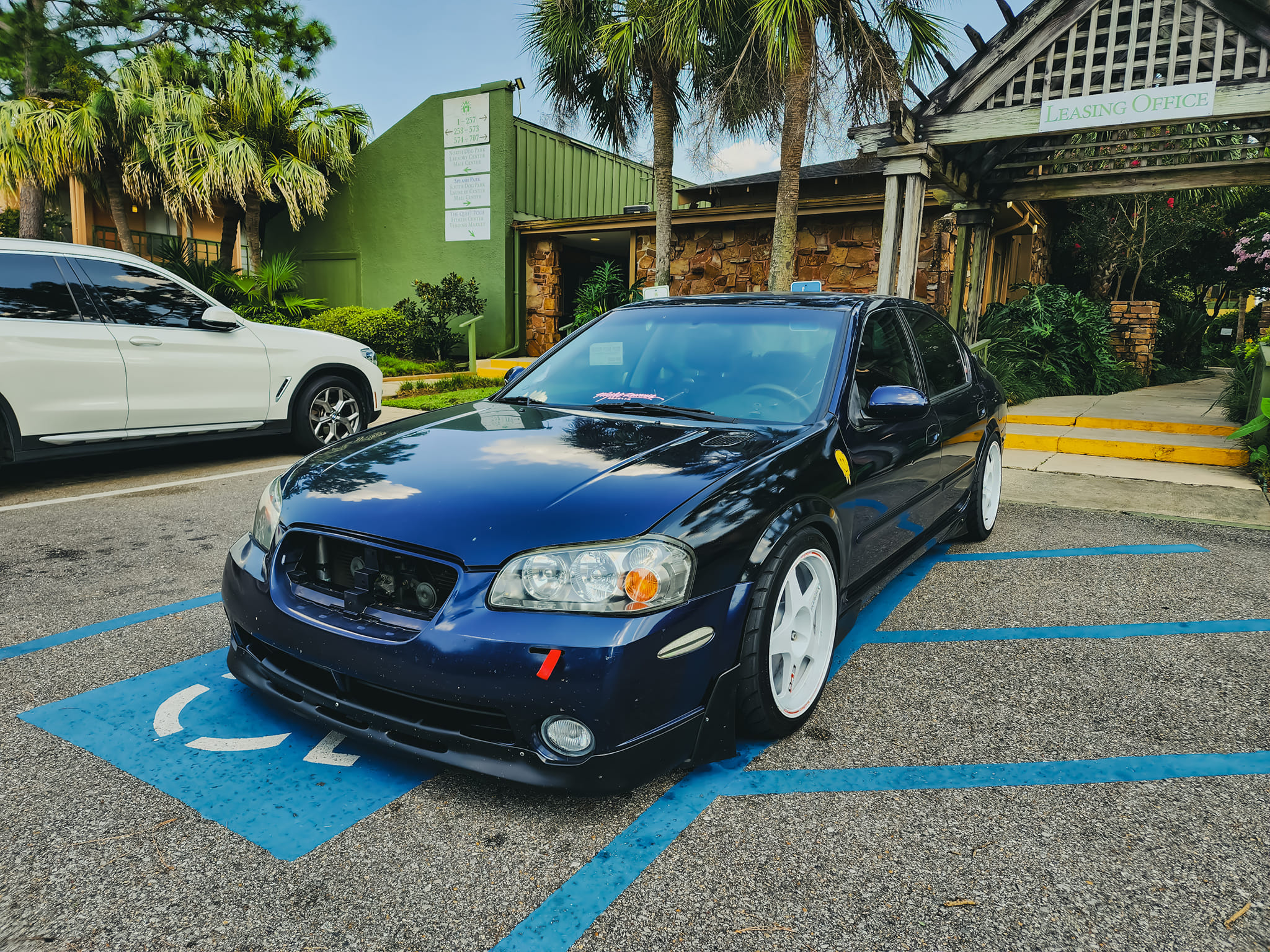
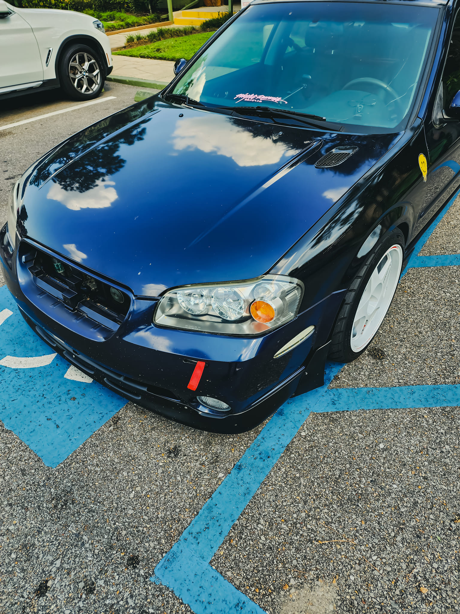
– Color-matched Gloss Black Grille
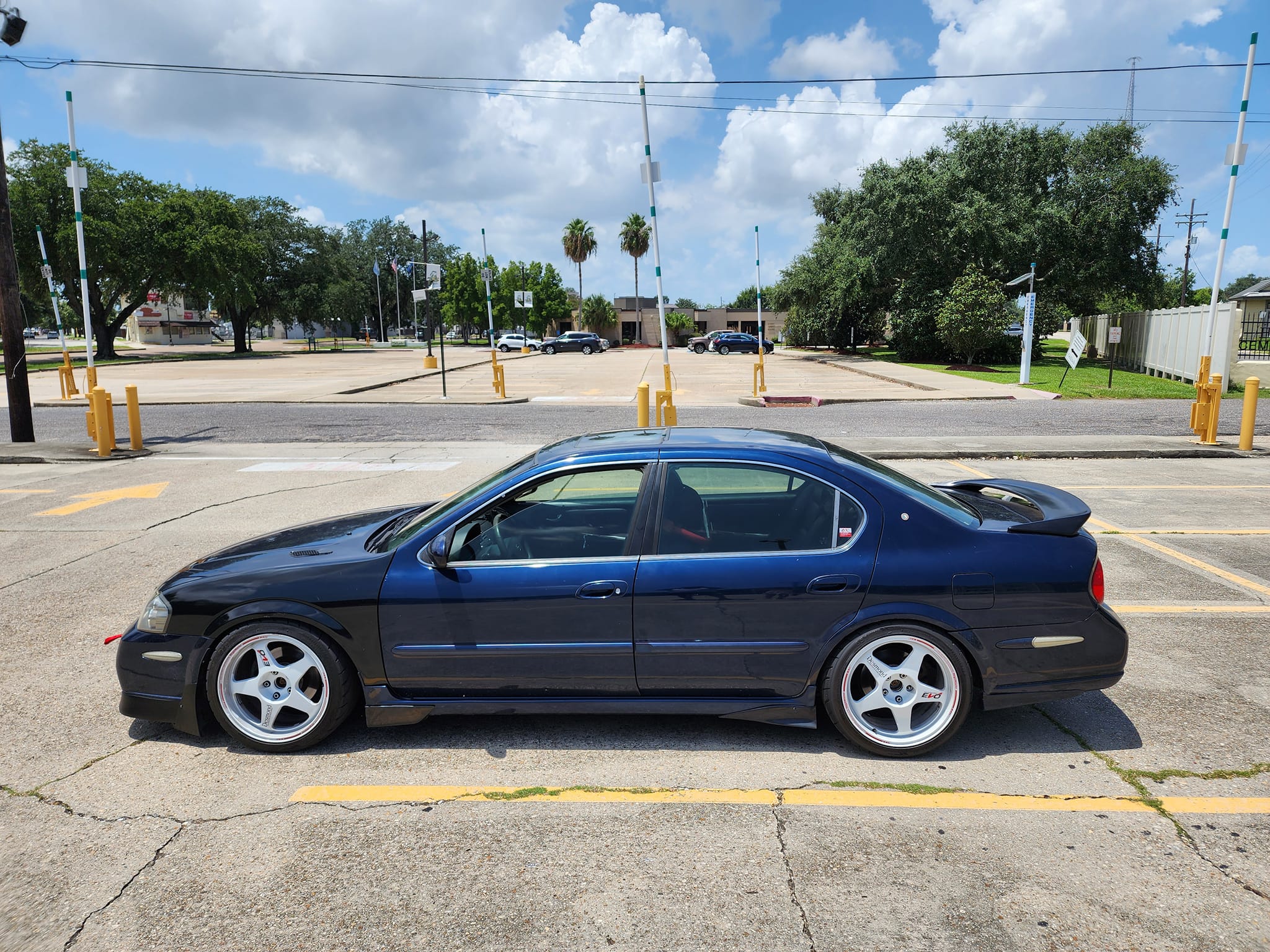
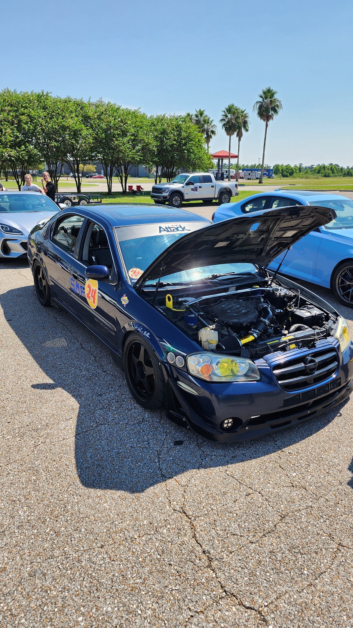
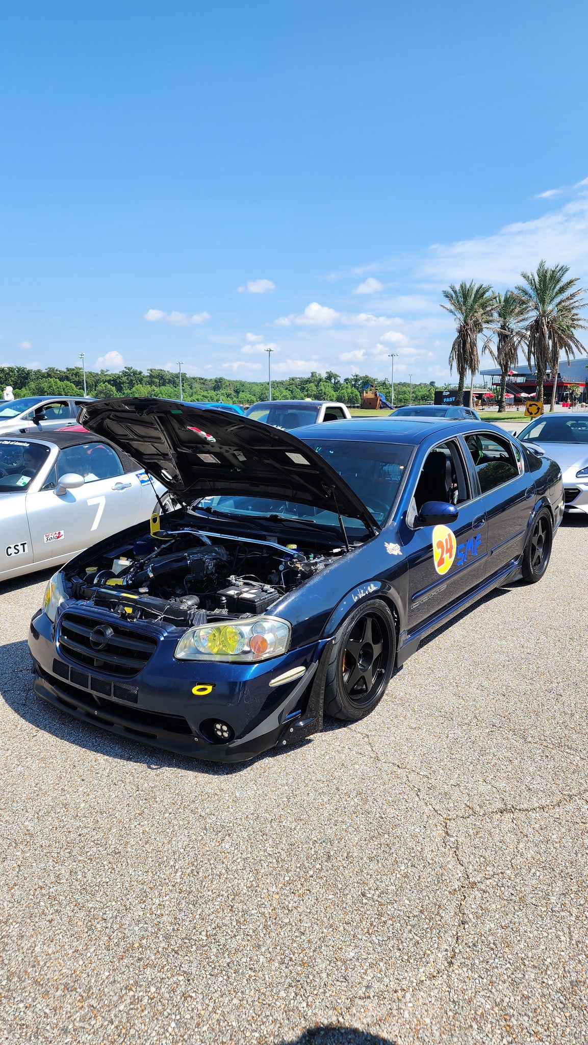
– VIS OEM-Style Carbon Fiber Hood with Aerocatch Hood Latches
– FibreCustoms Trimmed V2 Eyelids
– Stillen “Classic” Urethane Front Lip
– TrimBrite Blackout Tape Window Trim Mod
– Ionic Dynamics 20th Anniversary Edition Replica Rear Valence
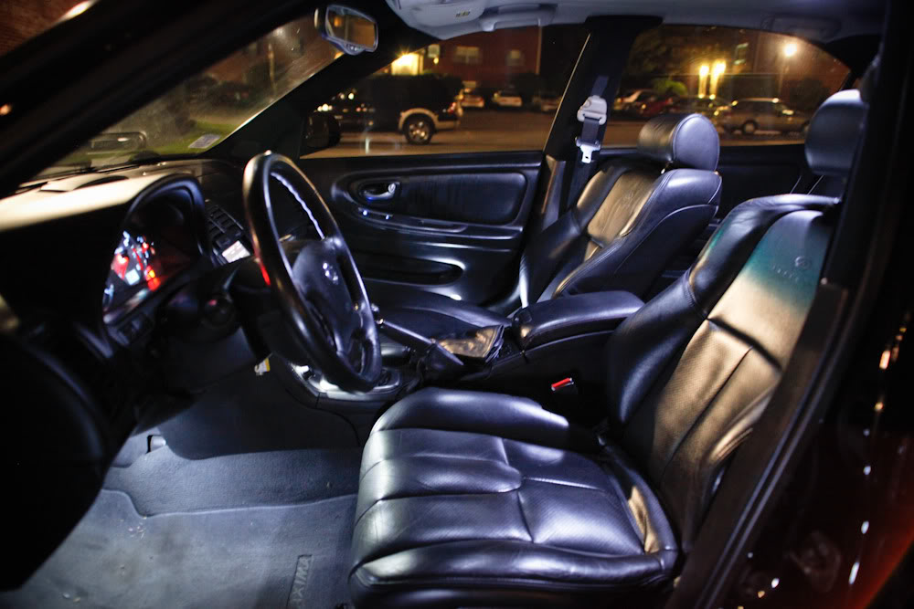
Interior:
– G35 Coupe Black Leather Seats – Front
– 20th Anniversary Edition Door Sills
– 20th Anniversary Edition Pedals + 350Z Dead Pedal
– RedLineGoods Armrest Cover, Shift Boot, and E-Brake Boot – Black Leather w/ Red Stitching
– MDF Trunk Floor
– Black Microsuede Pillars and Rear Deck
– TheTuningShop Aluminum Gauge Rings
– Pioneer AVH-P1400DVD Headunit
Lighting:
– OEM Headlights customized by X-Vert / OnEighty
— Partial Gloss black housing
— Cleared amber reflector
– Custom LED Conversion by Dark-V
— 1W LED White License Plate Lights
— 24-LED White Dome Light
— 24-LED White Footwell Lights
— 12-LED White Map Lights
— Blue LED Window/Lock Switches
— 16-LED White Courtesy Door Lights
– LED Converted HVAC Controls by Shinjiduo
– Smoked Sidemarkers
– Nokya Super White 194 Sidemarker Bulbs
– Cool White Gauge Cluster LEDs
– VLEDs 6000k HID D2R bulbs
– DDMTuning 6000k HID H3 55W foglights
– Fog Rewire Mod
Engine and Drivetrain:
– Berk Short Ram Intake w/ APEX’i Air Filter
– Energy Suspension Polyurethane Shifter Bushings
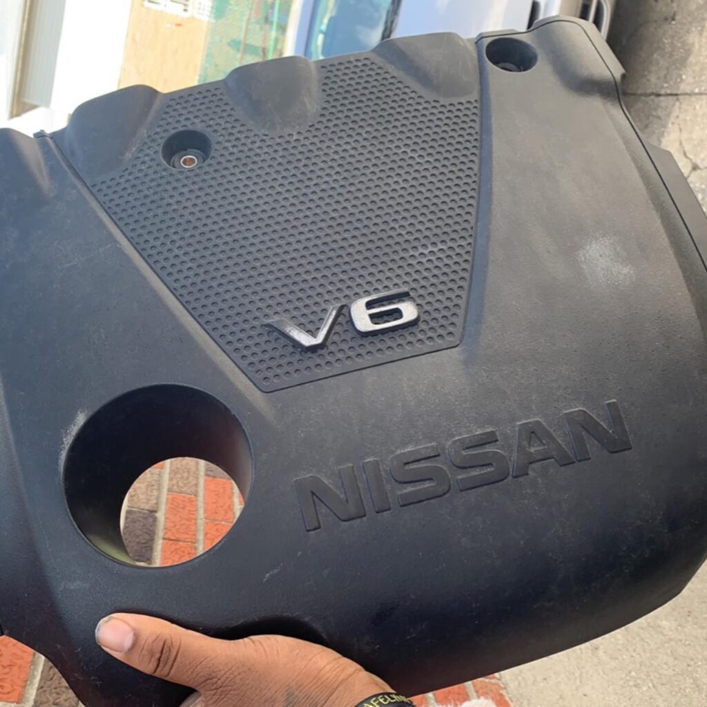
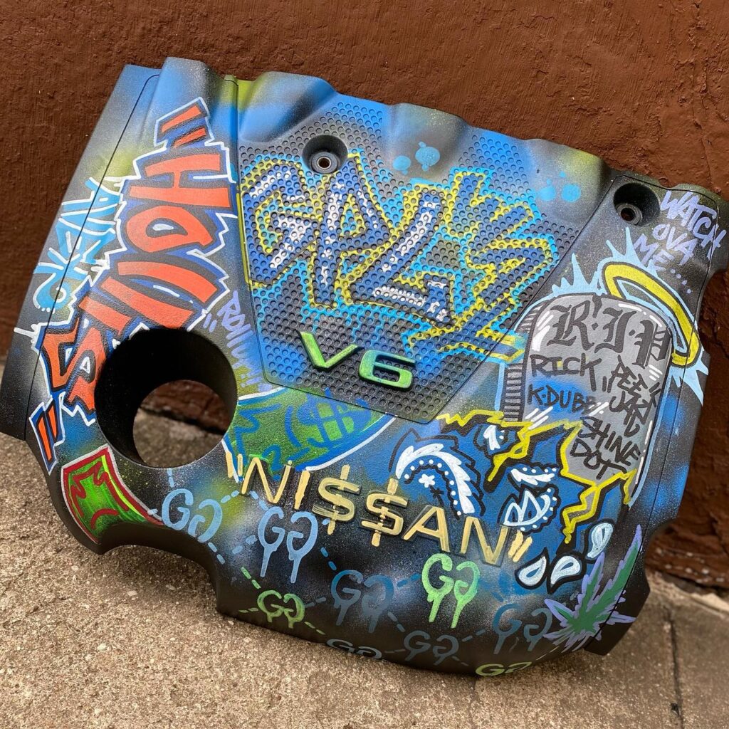
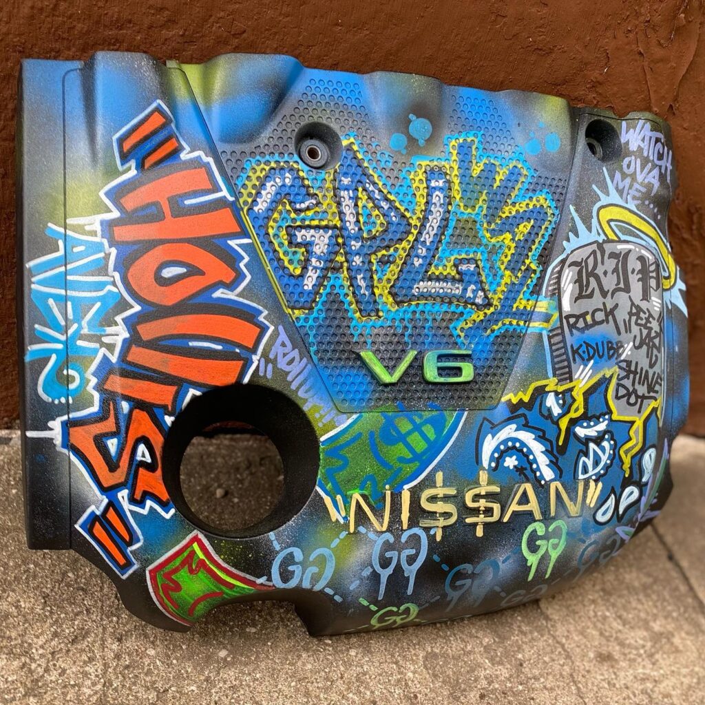
– Painted Gloss Black & Red “V6 3.5” Engine Cover
– Aluminum “Maxima” Battery Tie-down by sicivic89
– Timing Advanced to 17* (+2)
– Energy Suspension Motor Mounts
– 350Z Thermostat
– BigJ Short Throw Shifter Modification
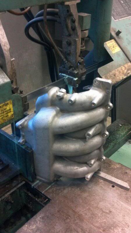
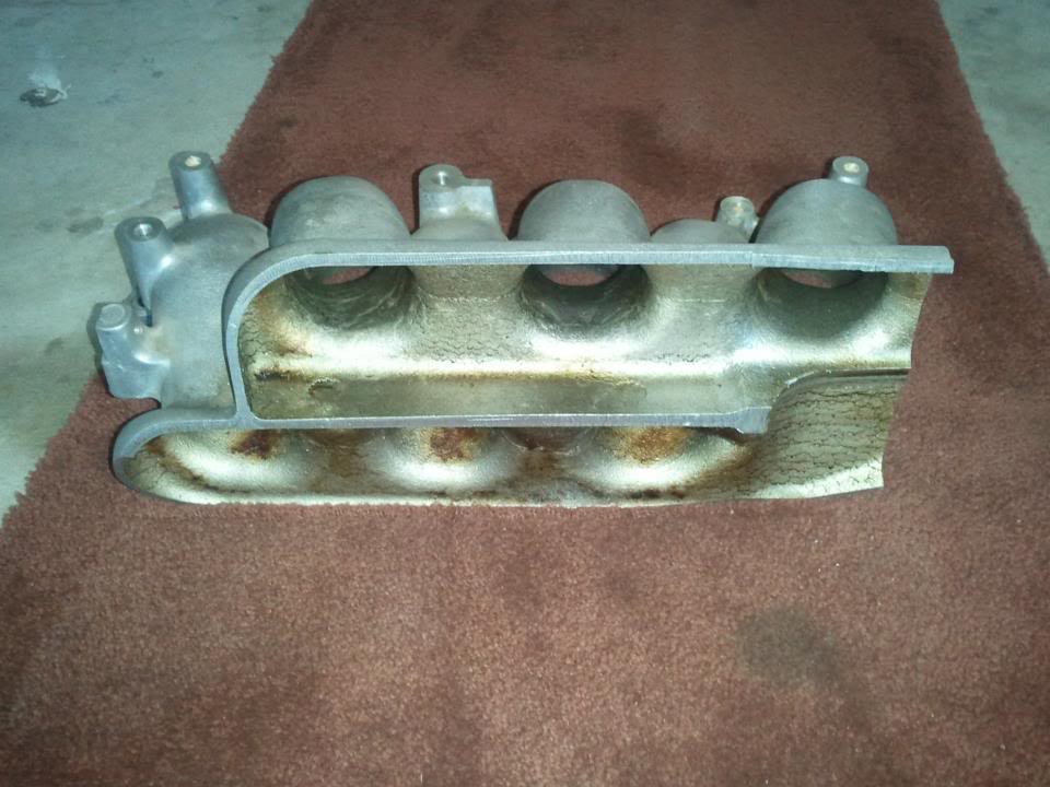
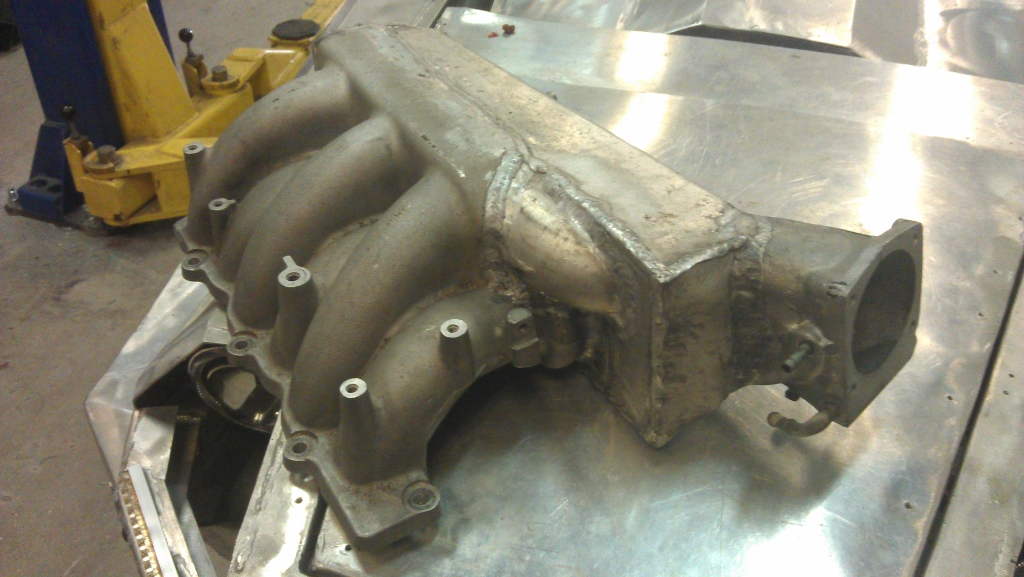
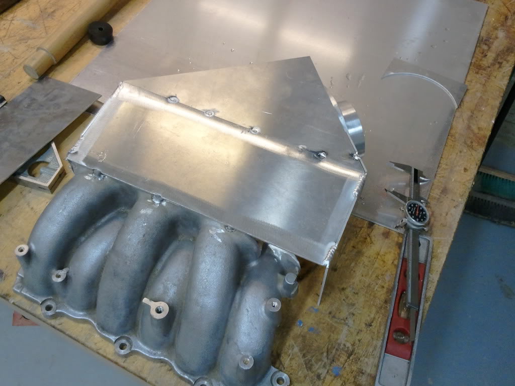
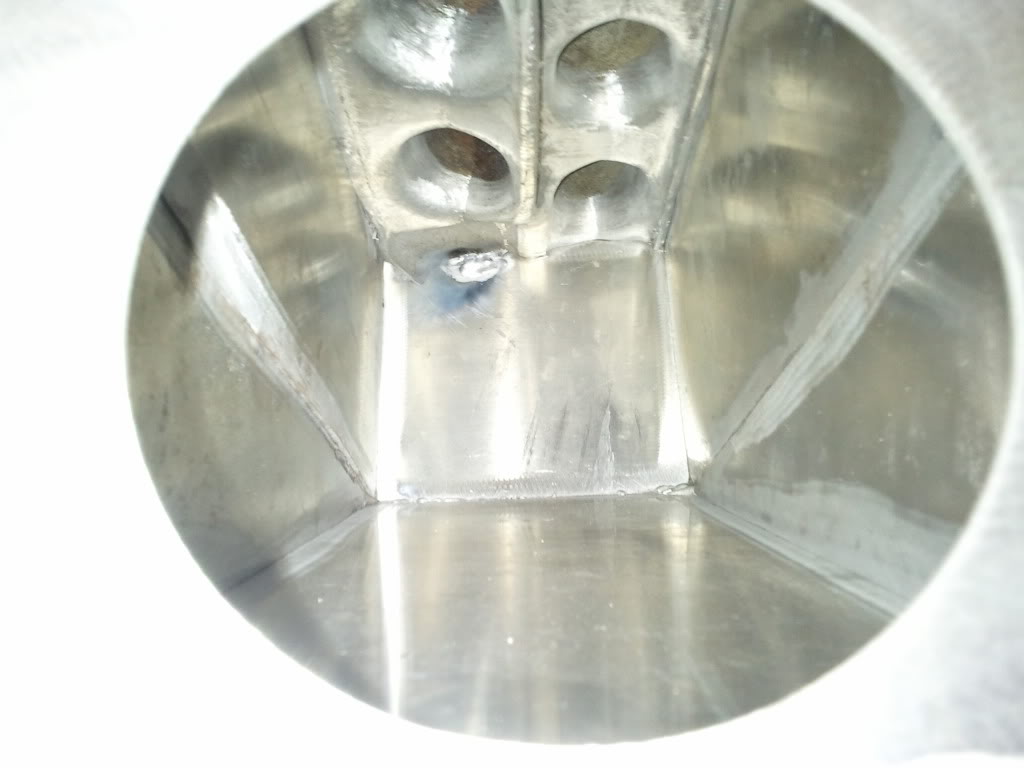
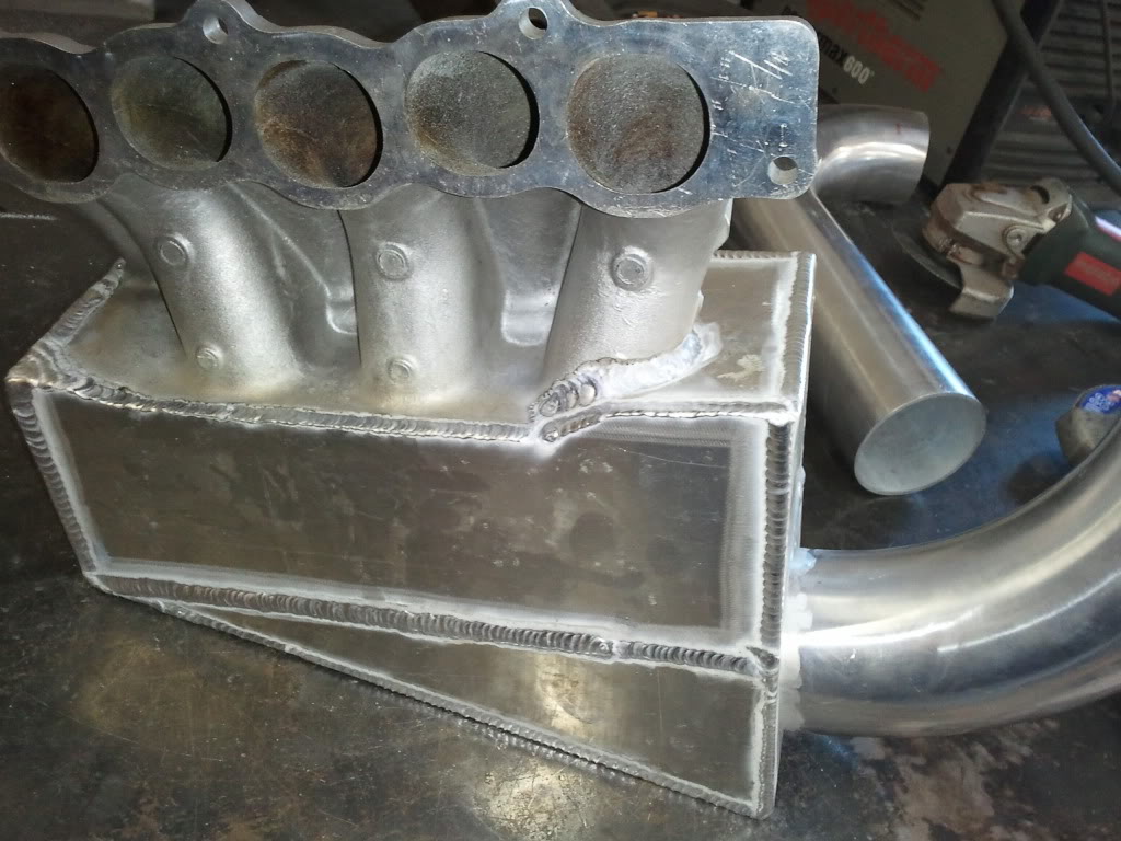
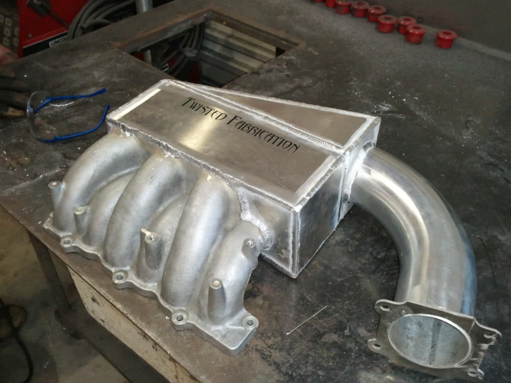
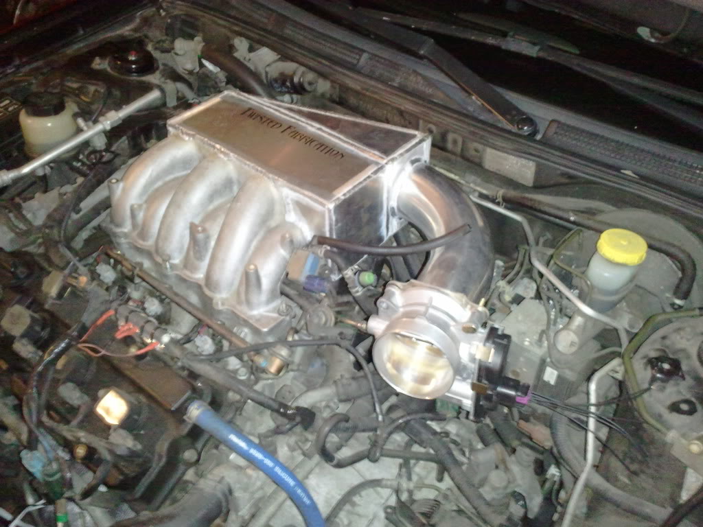
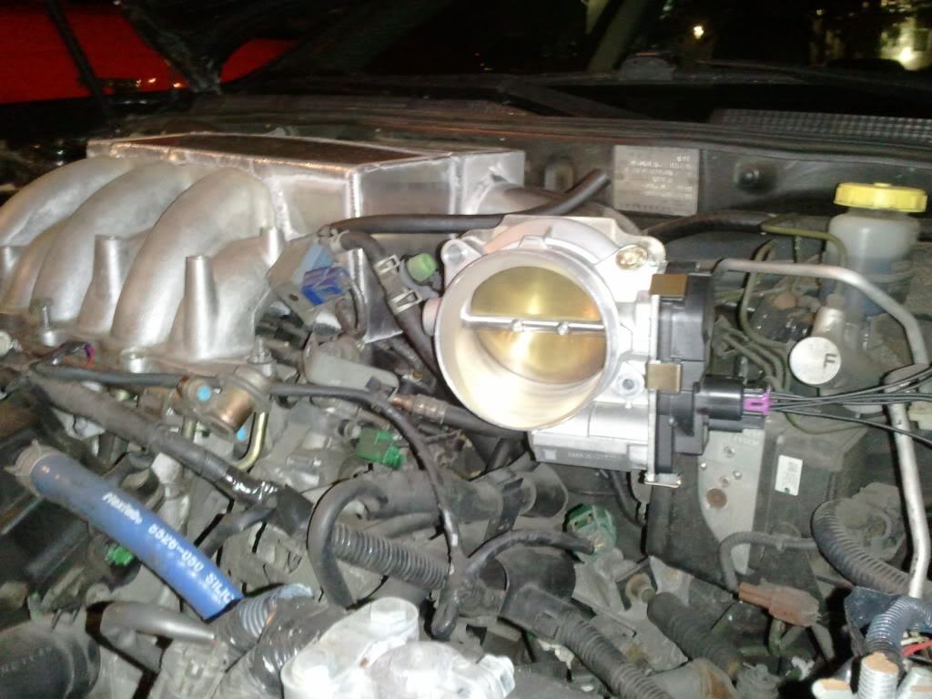
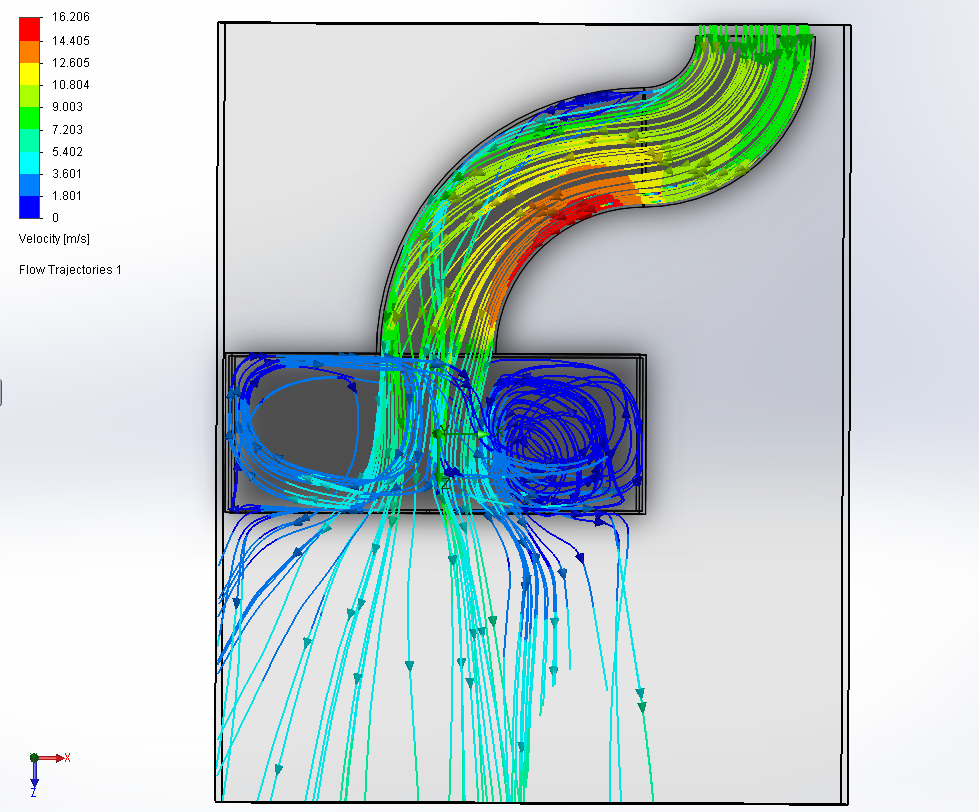
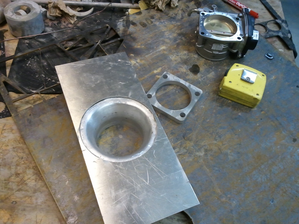
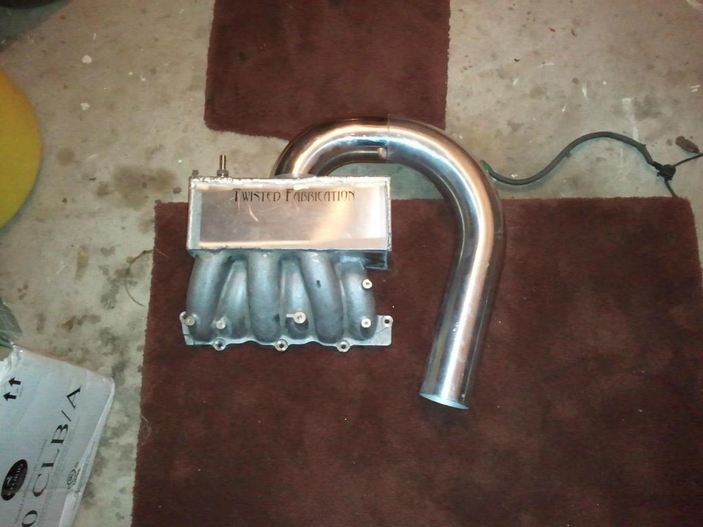
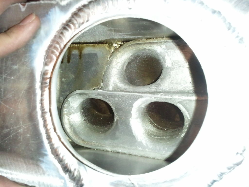
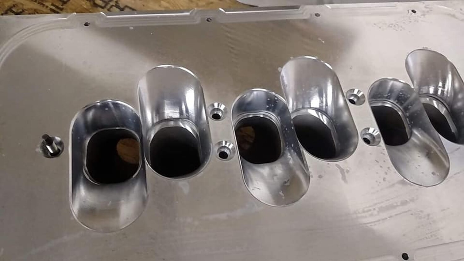
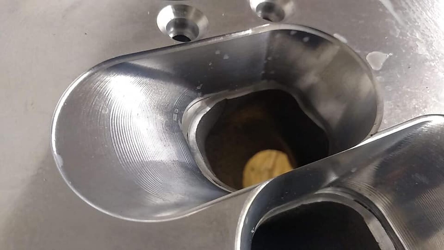
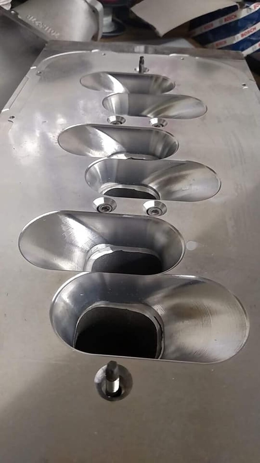
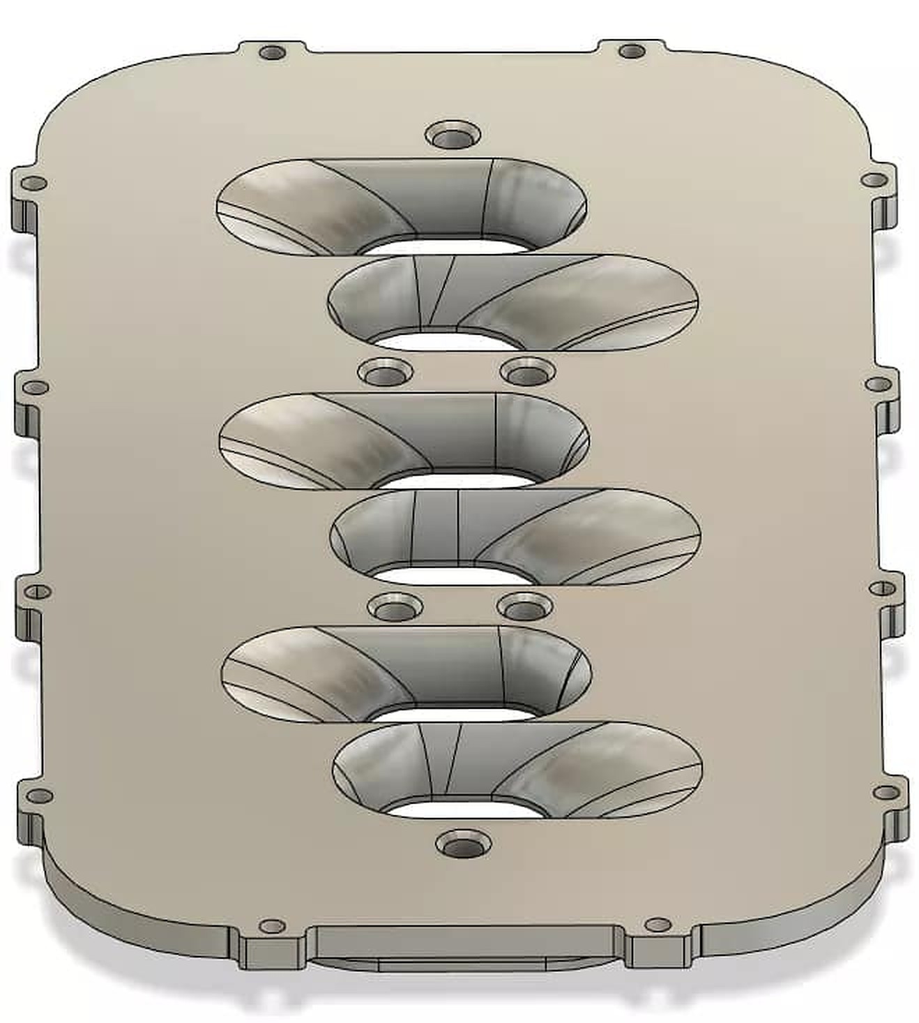
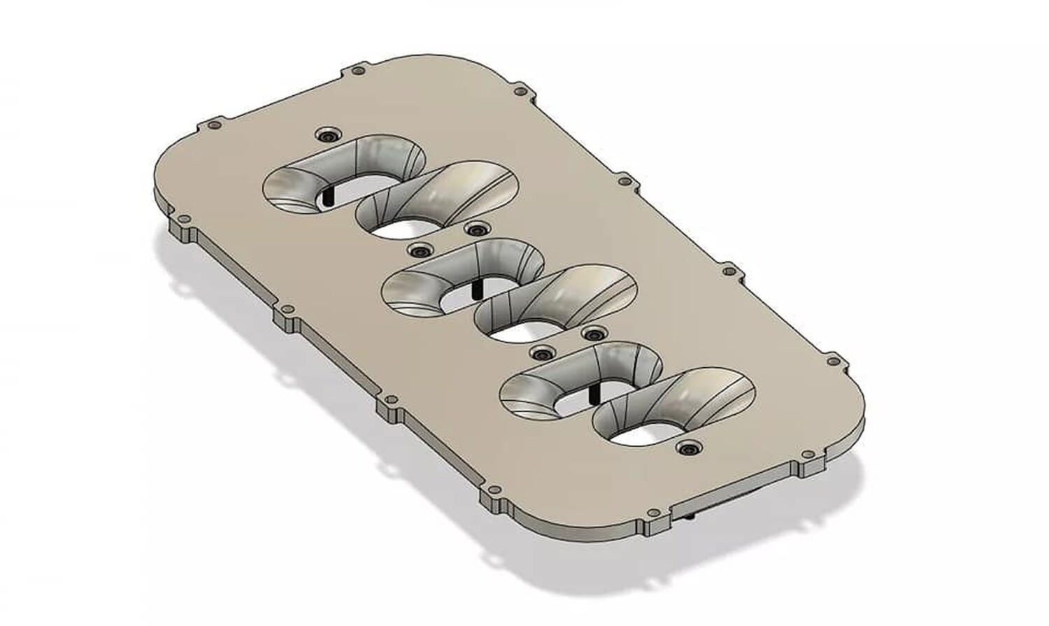
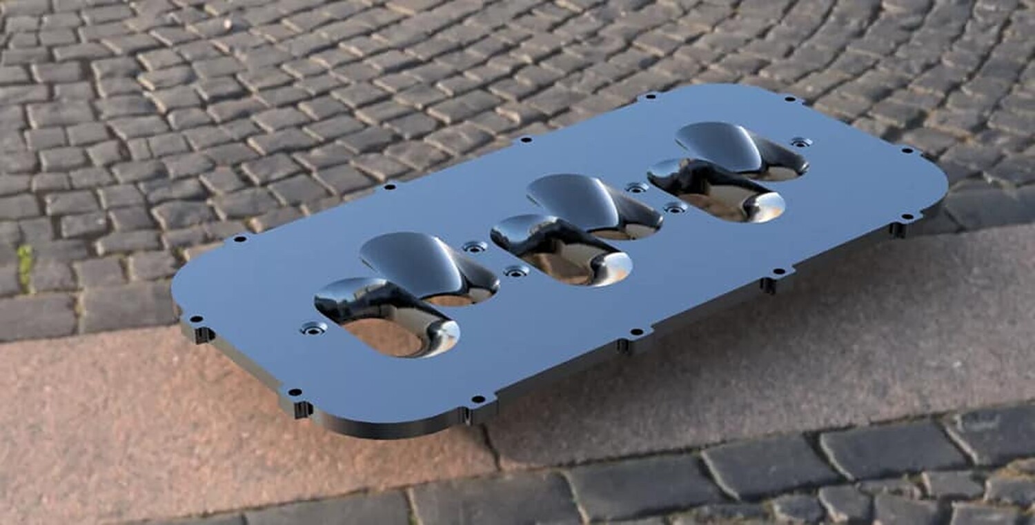
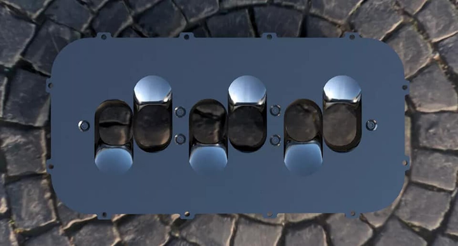
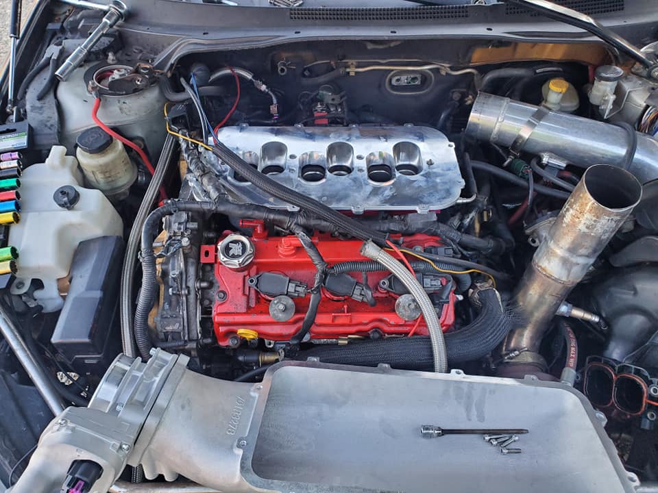
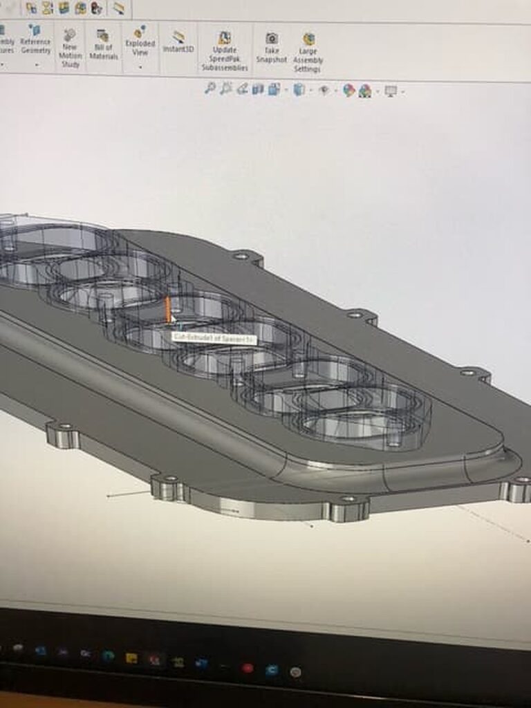
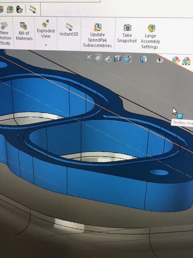
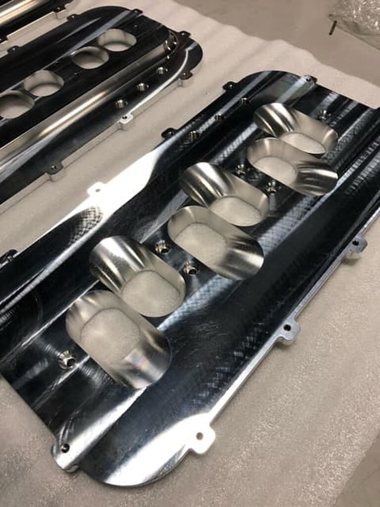
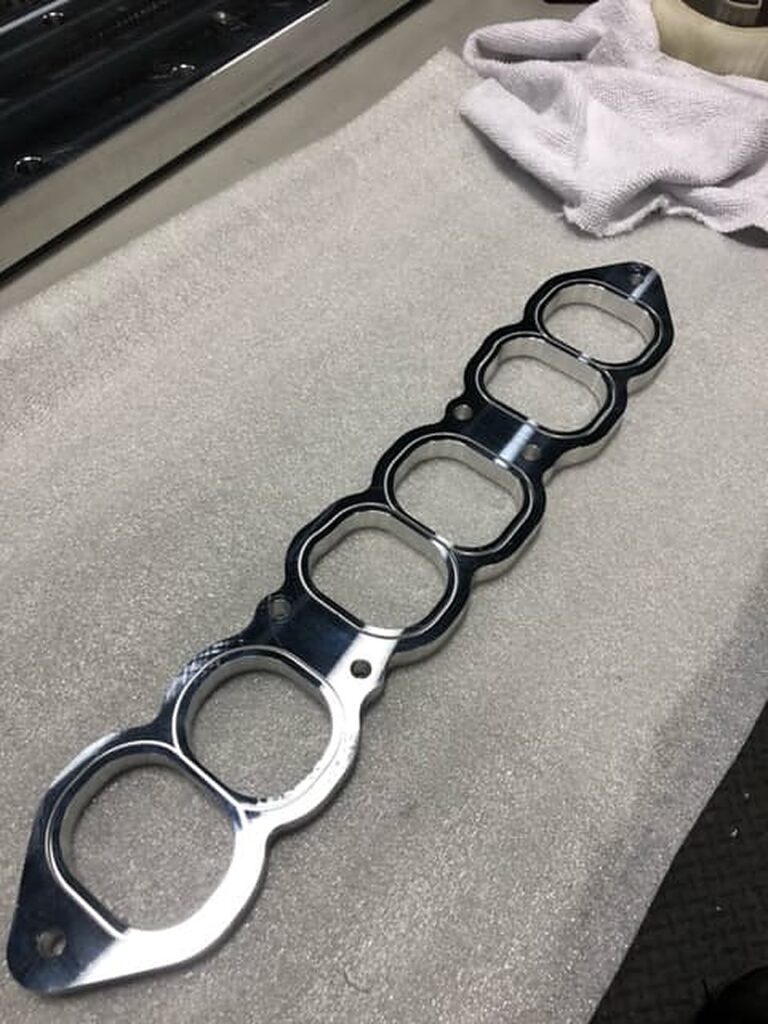
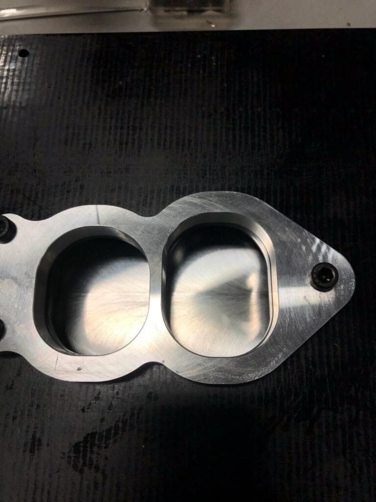
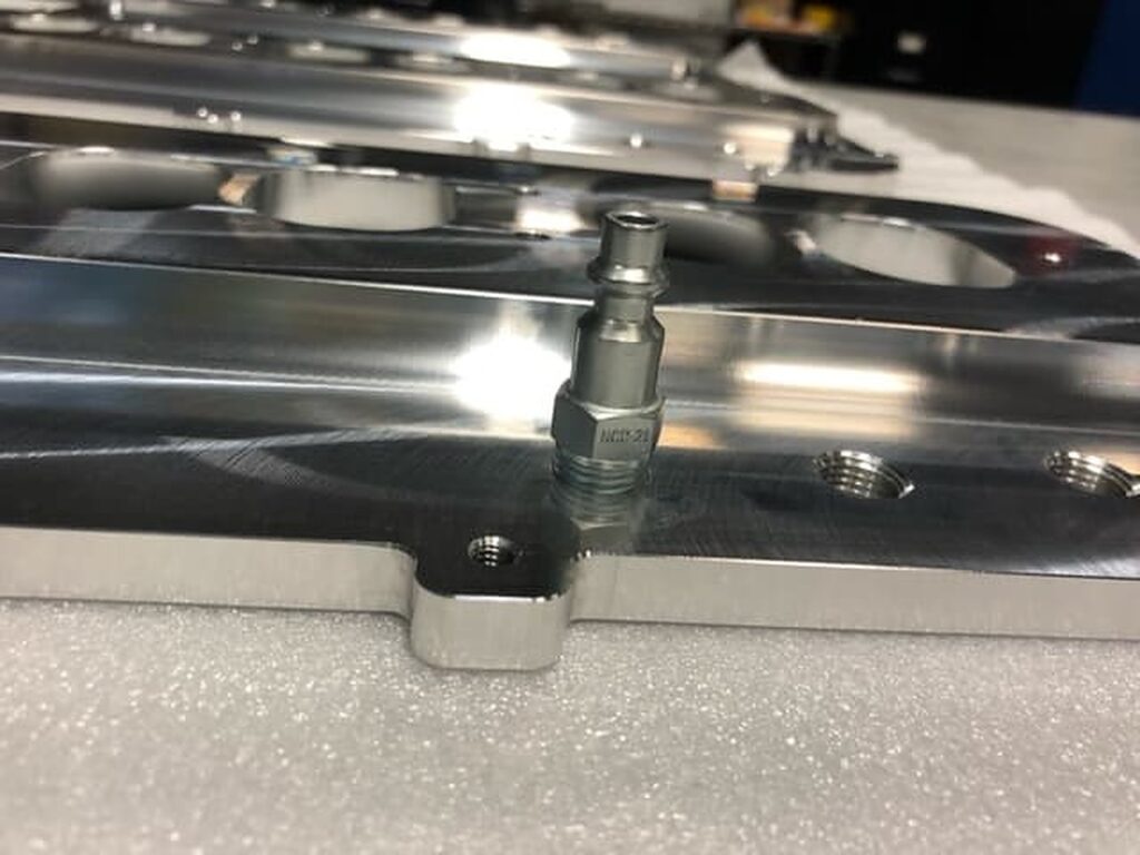
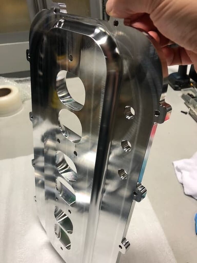
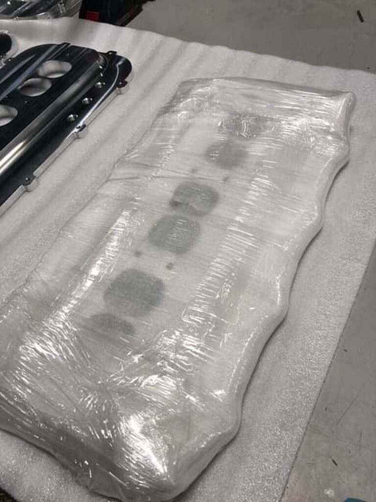
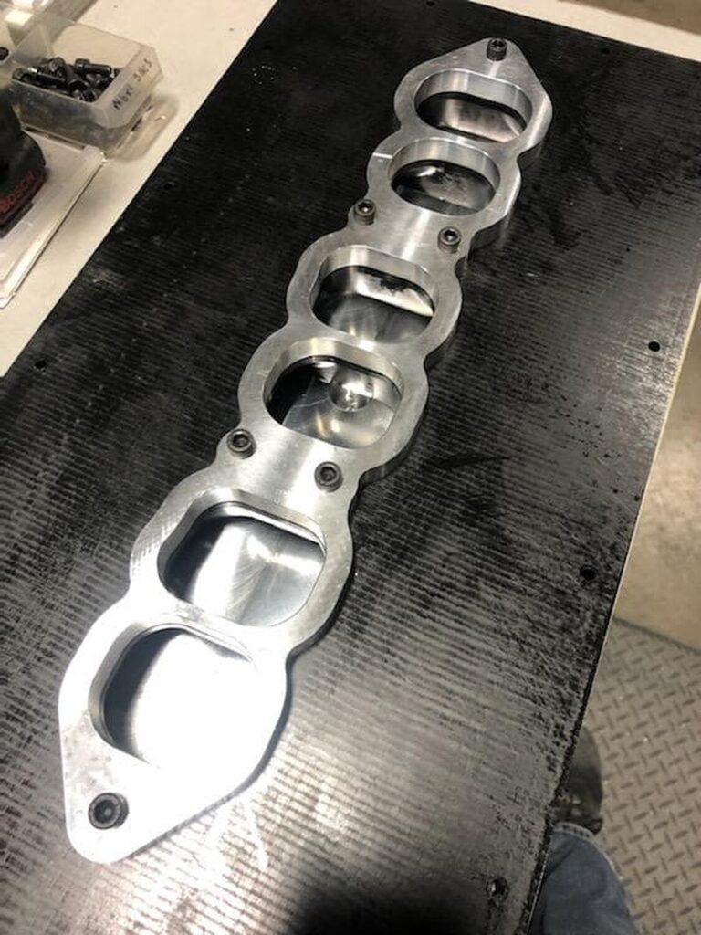
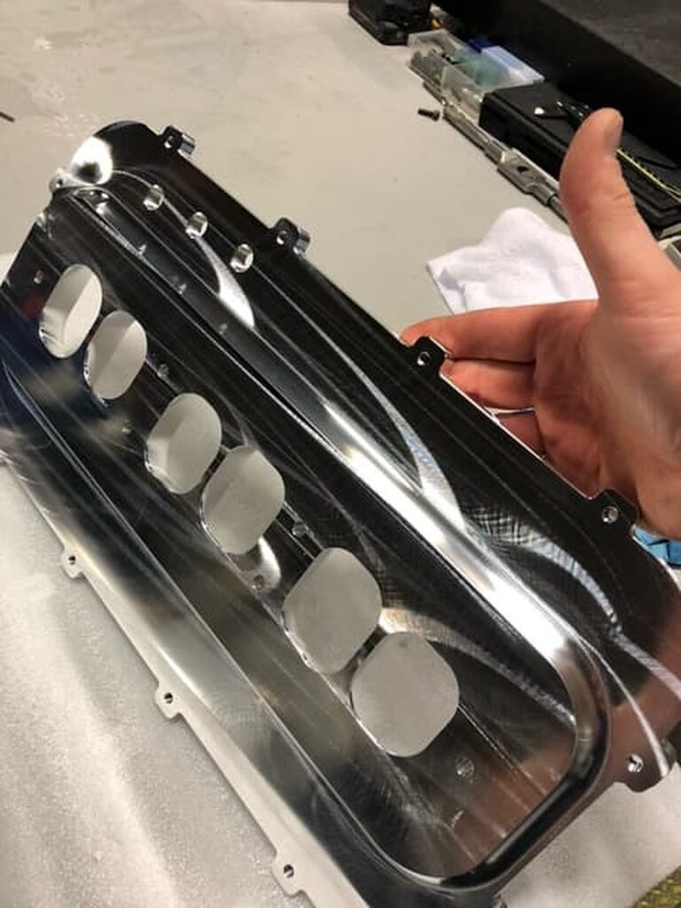
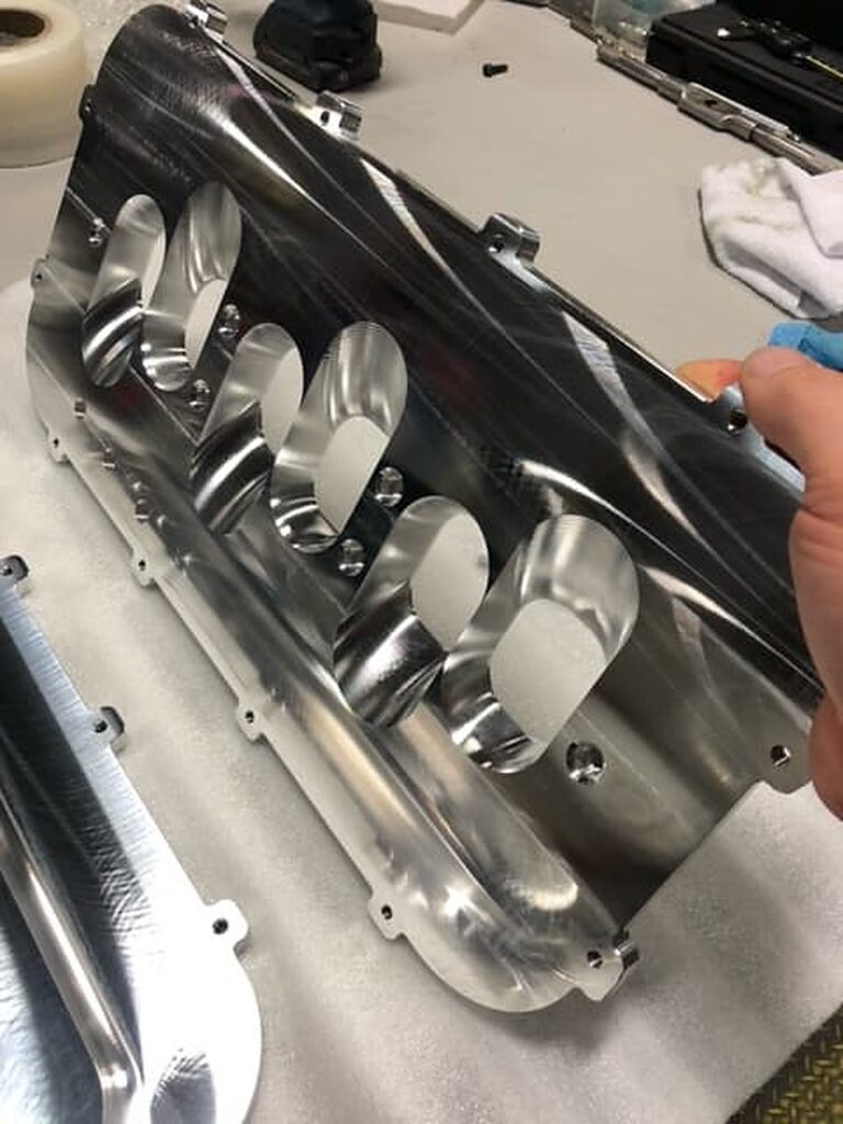
– SSIM “Secret Sauce Intake Manifold” by GoodwinMotorsports
– Stinger Expert Grounding Wire Kit by Shinjiduo
– NWP Engineering VIAS Removal Plate – Basic Version
– Koyo Radiator
– NWP Engineering Engine Torque Link Kit
– Cattman 3″ Catback Exhaust
– Cattman FastCat Hi-Flow Catalytic Converter
Suspension:
– CustomMaxima Front Strut Tower Brace – Red
– TEIN Super Street Coilovers (Off car, will sell with)
– Energy Suspension Polyurethane Lower Control Arm Bushings
– Progress Rear Sway Bar
– Kuo’s Garage Adjustable Rear Beam Link
– Carnal_C30 Subframe Collars
– vsamoylov Aluminum Steering Bushing
Braking:
– RaceTech Performance Slotted Rotors
– Akebono Ceramic Pads
– Technafit Stainless Steel Brake Lines
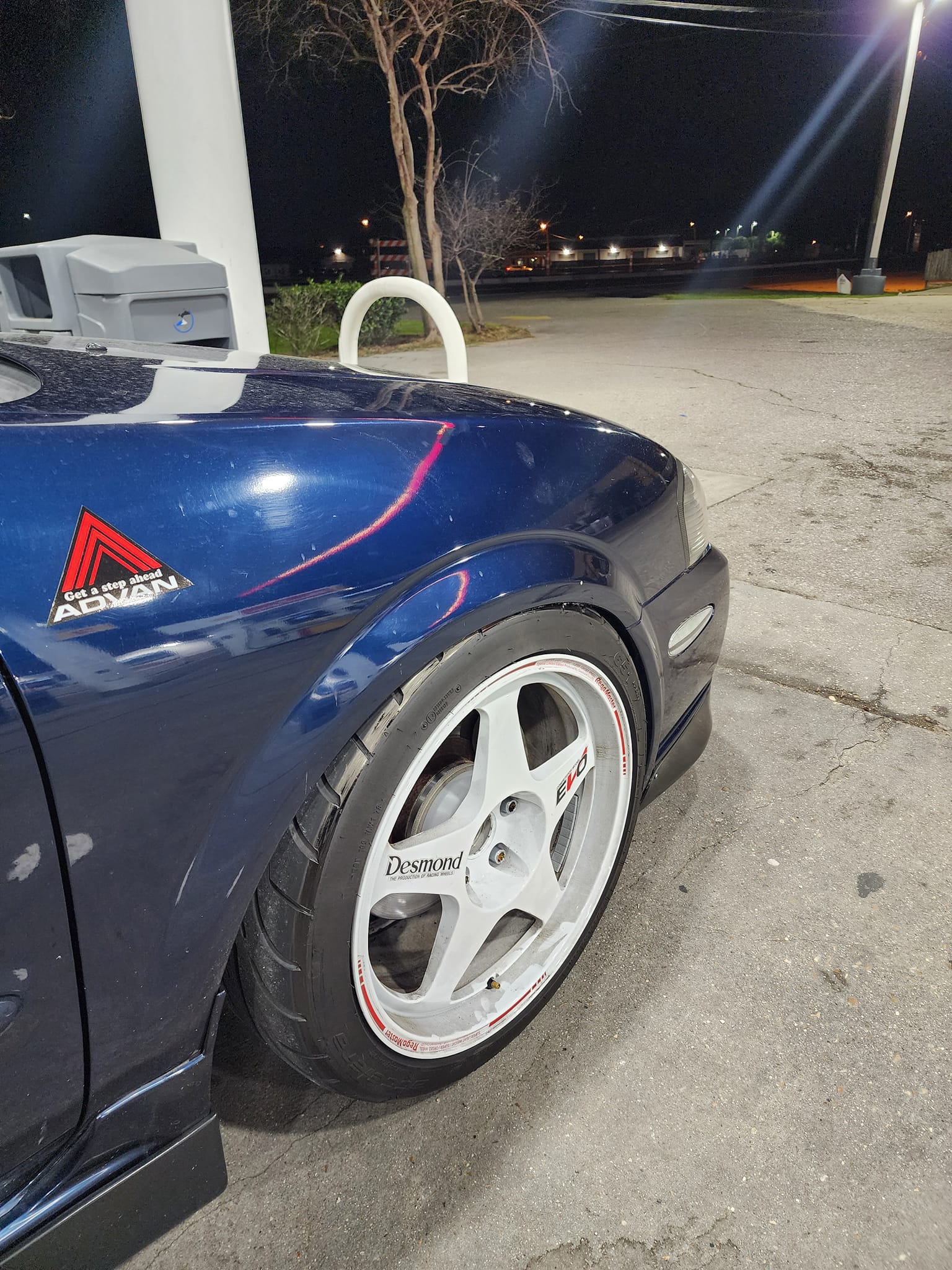
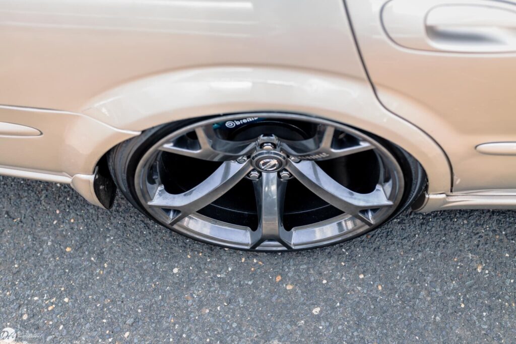
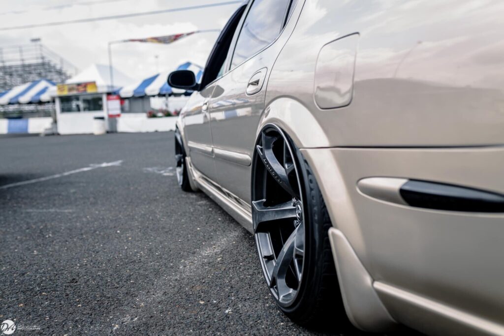
Wheels and Tires:
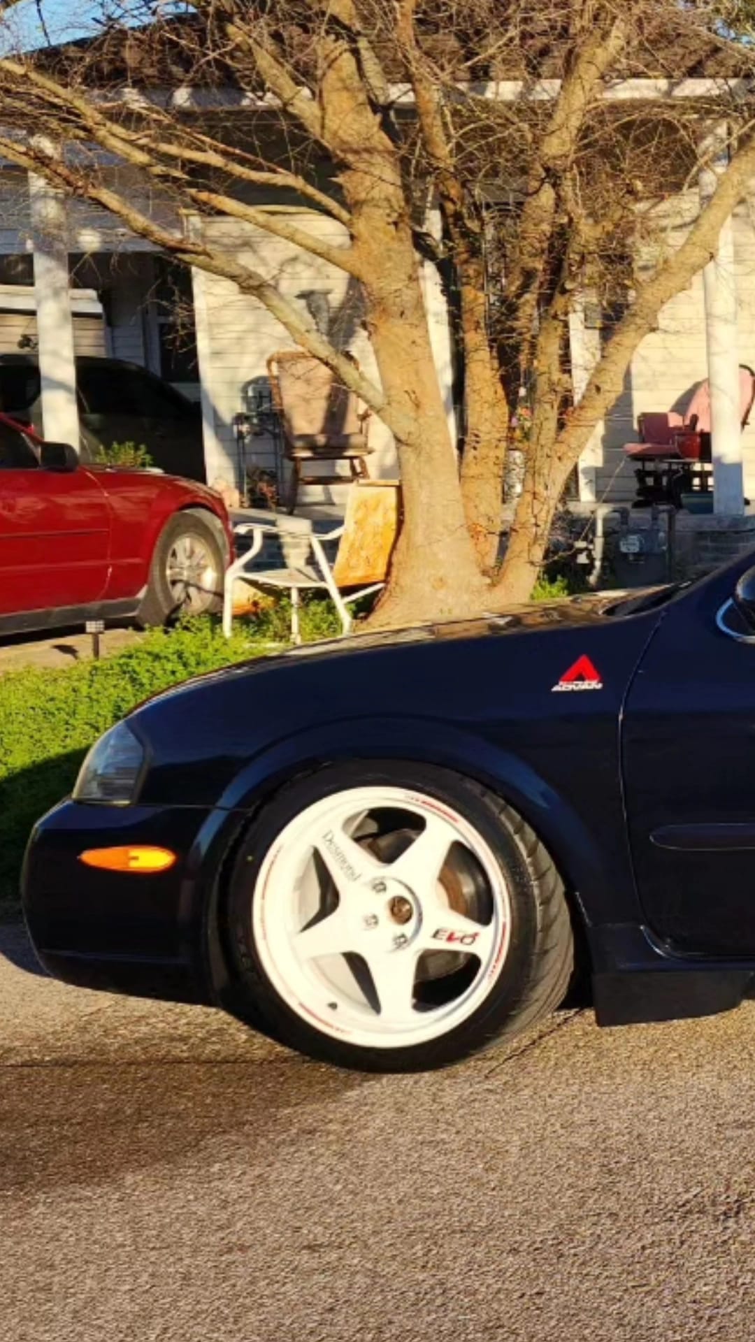
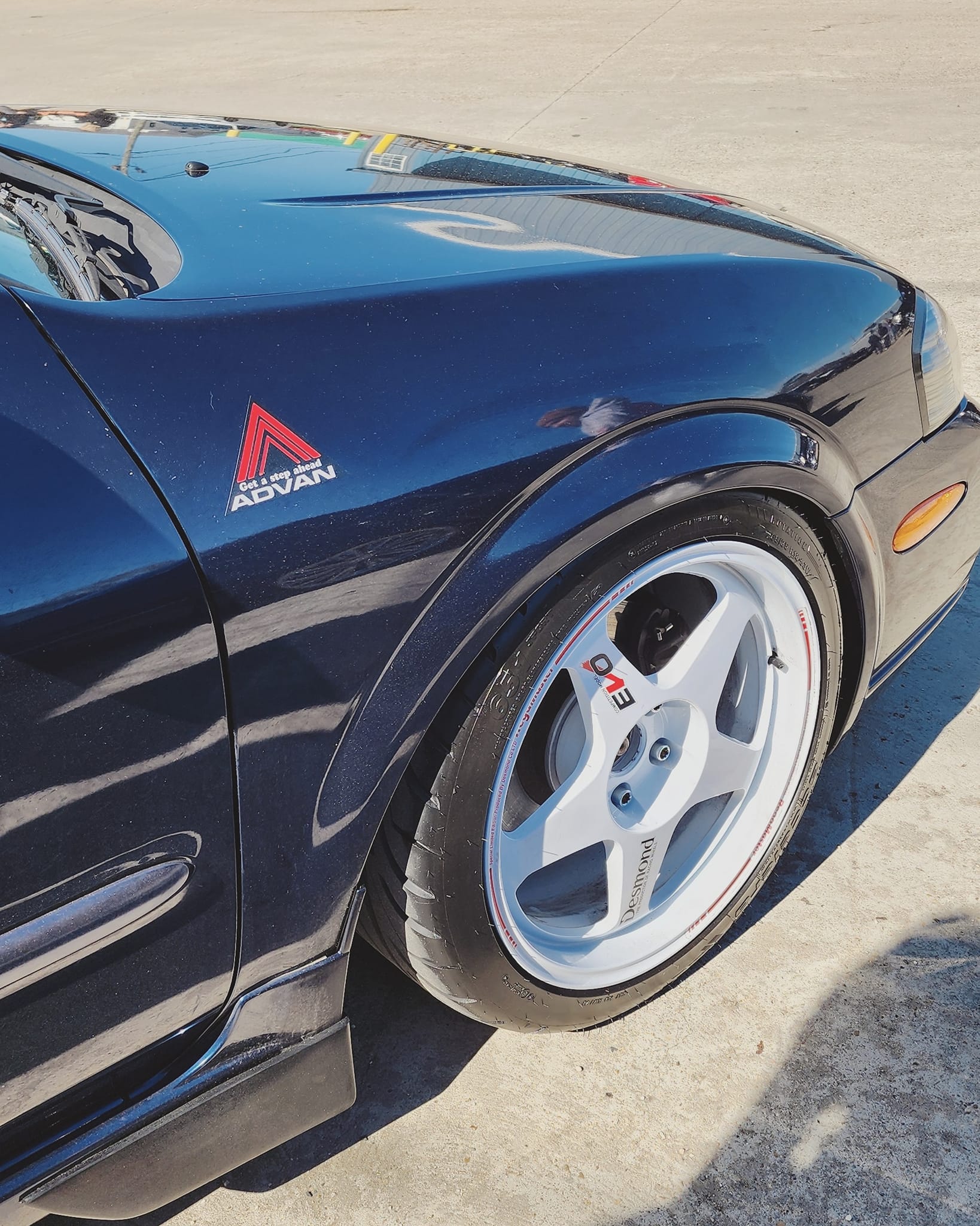
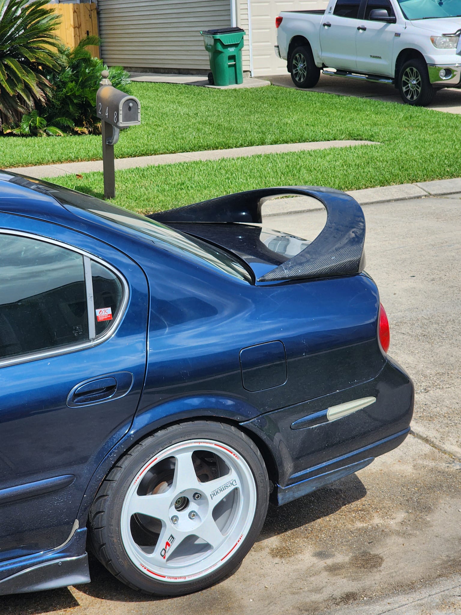
– 18×8 (F) 18×8.5 (R) 350Z Track Forged Aluminum Wheels
– 245/40-18 Hankook Ventus V12 (F) General Exclaim UHP (R) Summer Tires
Fluids:
– Pennzoil Platinum 5w30 Motor Oil every 3,000 miles
– AMSOIL 75w-90 GL-4 Synthetic Manual Gear Oil
– ATE Super Blue Racing Brake/Clutch Fluid
– Toyota Red Coolant w/ Water Wetter
![]()

")


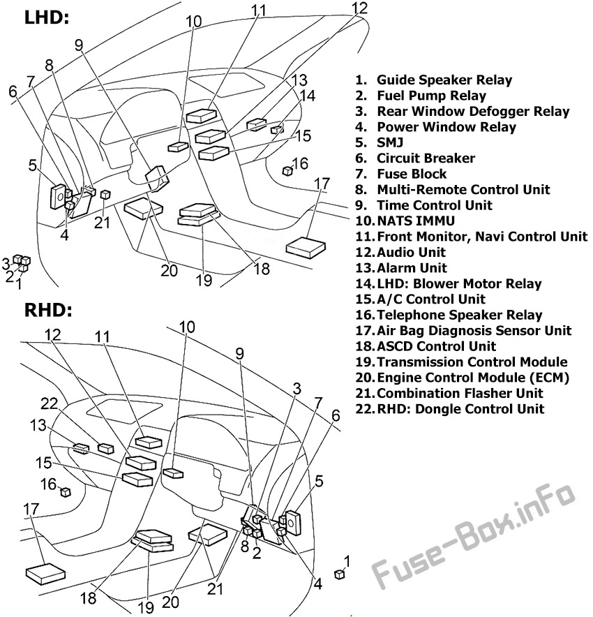
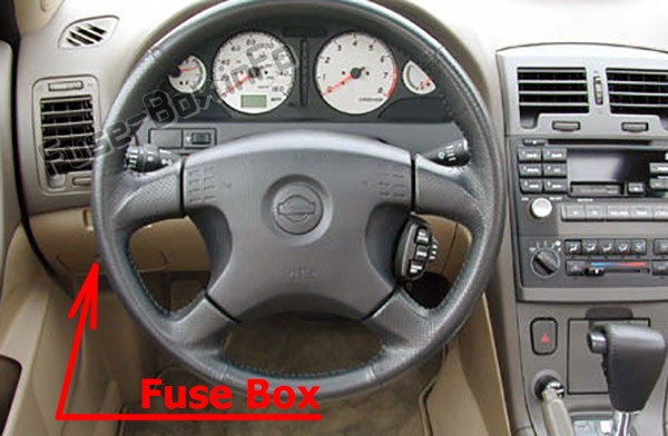
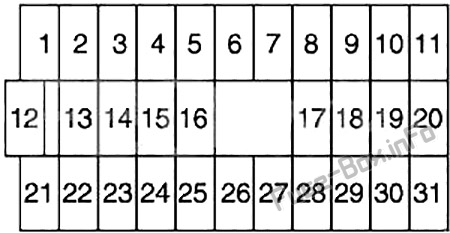
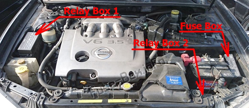
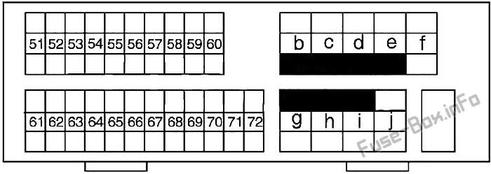
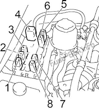
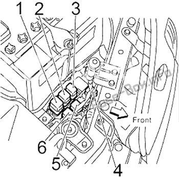
 Fuses and Relays Diagrams")