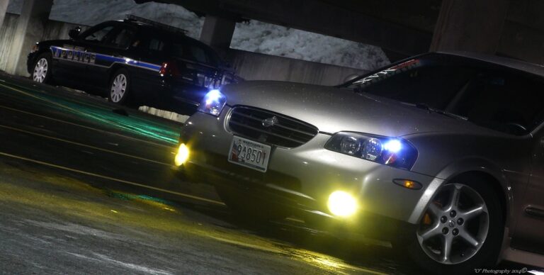
Owner: Omar Baker
Year: 2001
Model: Maxima
Color: Silver
Transmission: 4-Speed Automatic
Trim: SE




Owner: Omar Baker
Year: 2001
Model: Maxima
Color: Silver
Transmission: 4-Speed Automatic
Trim: SE
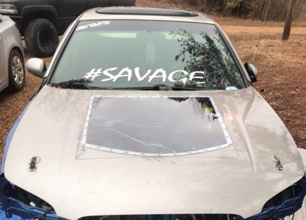
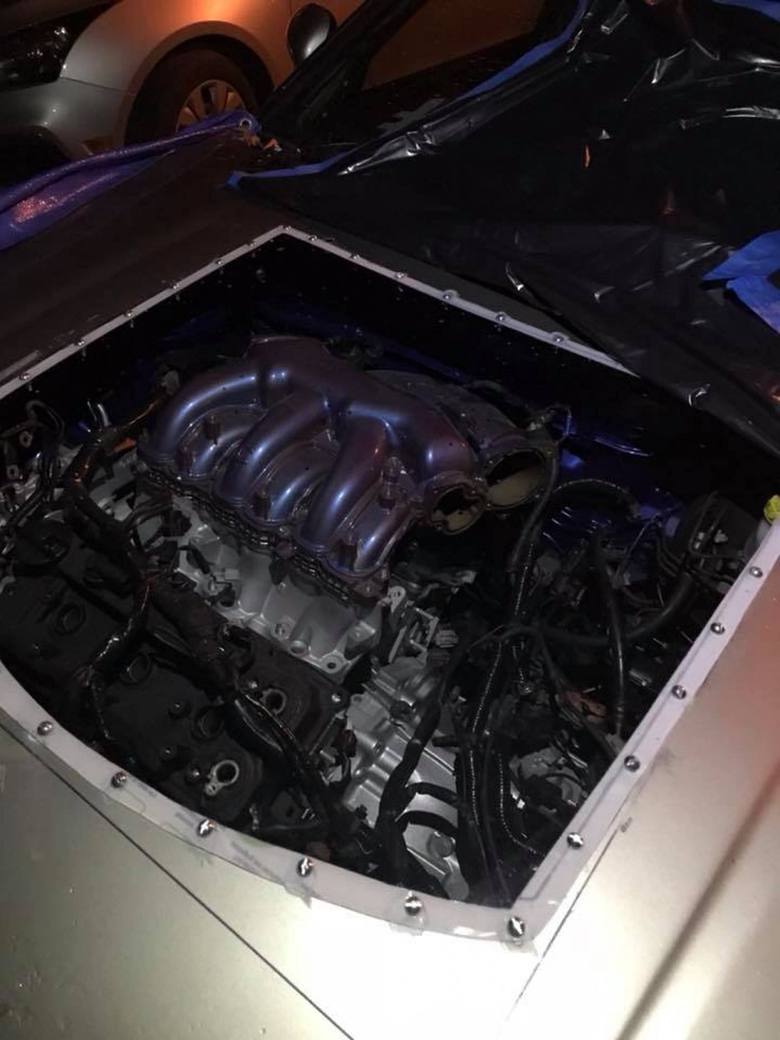
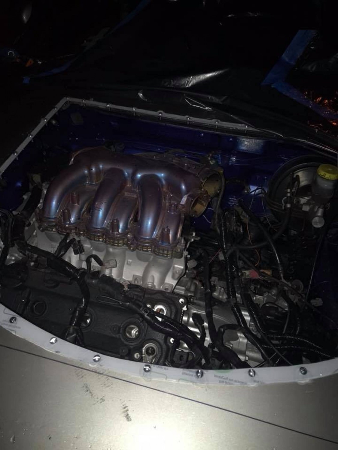
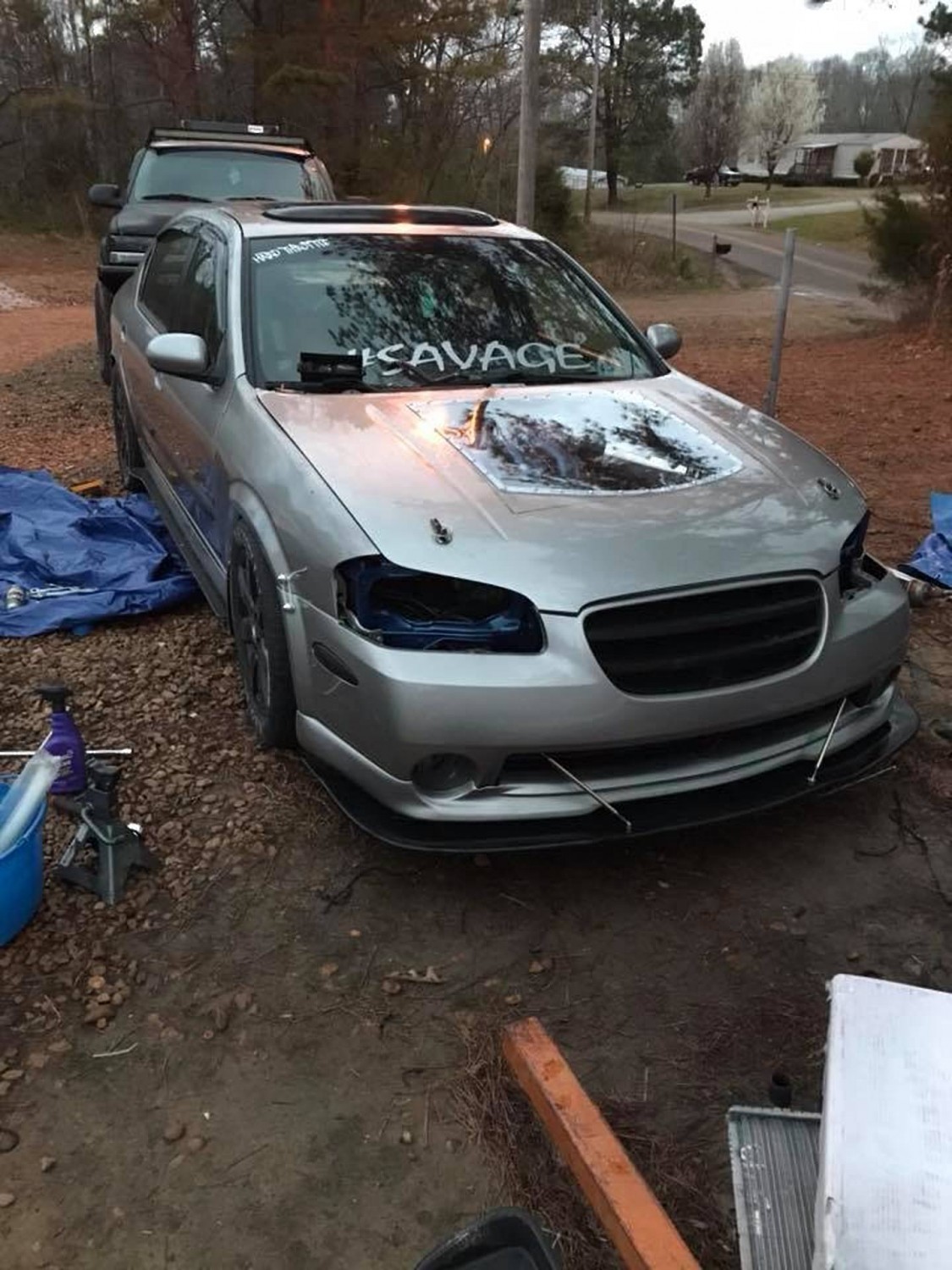
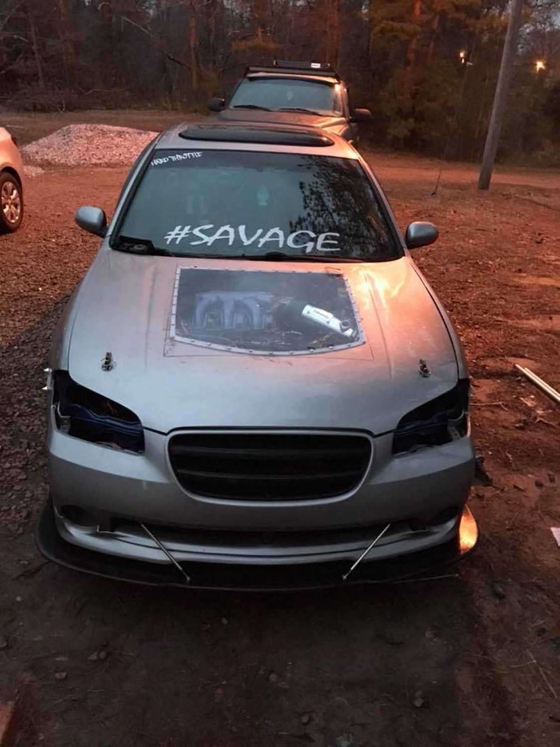
Member Credit: Shaquille Keon Jenkins
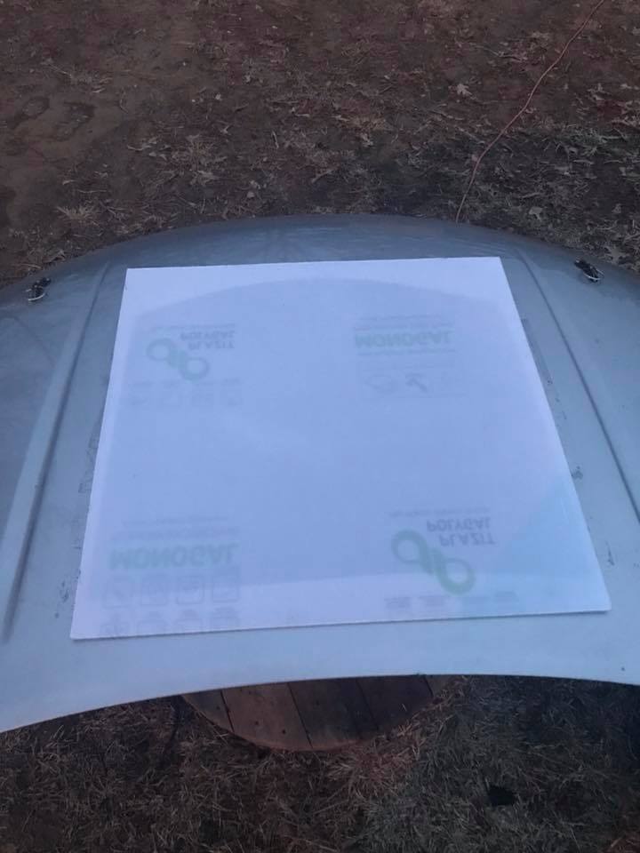
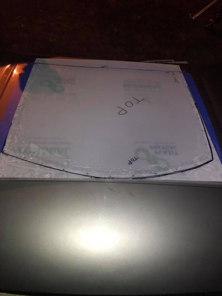
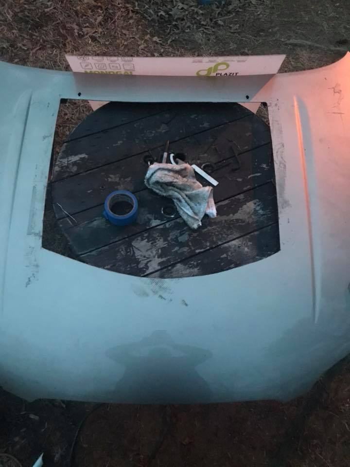
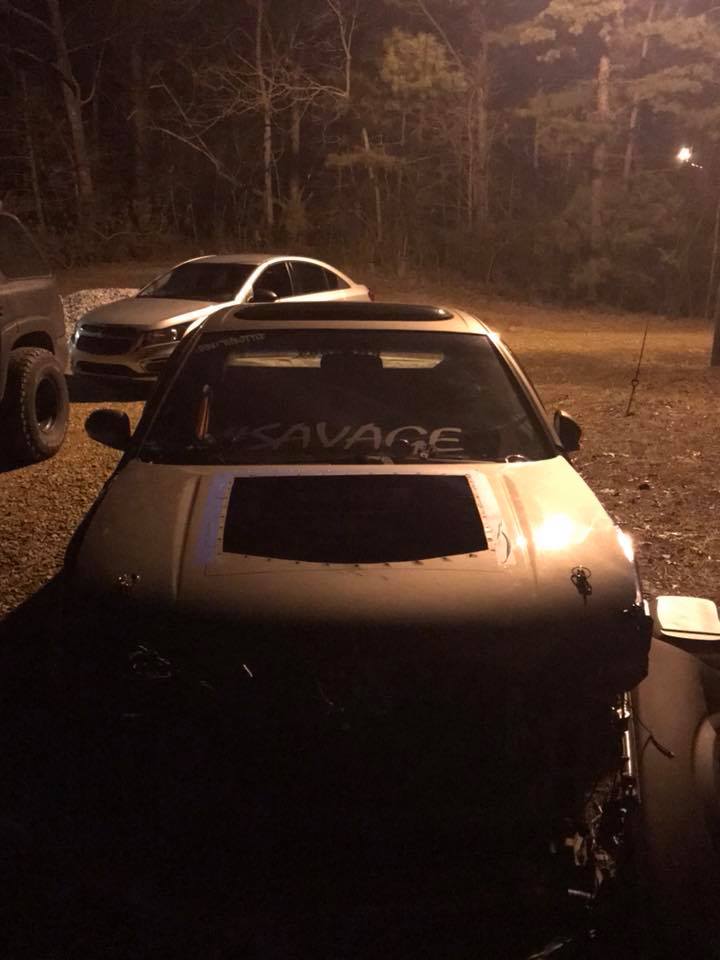
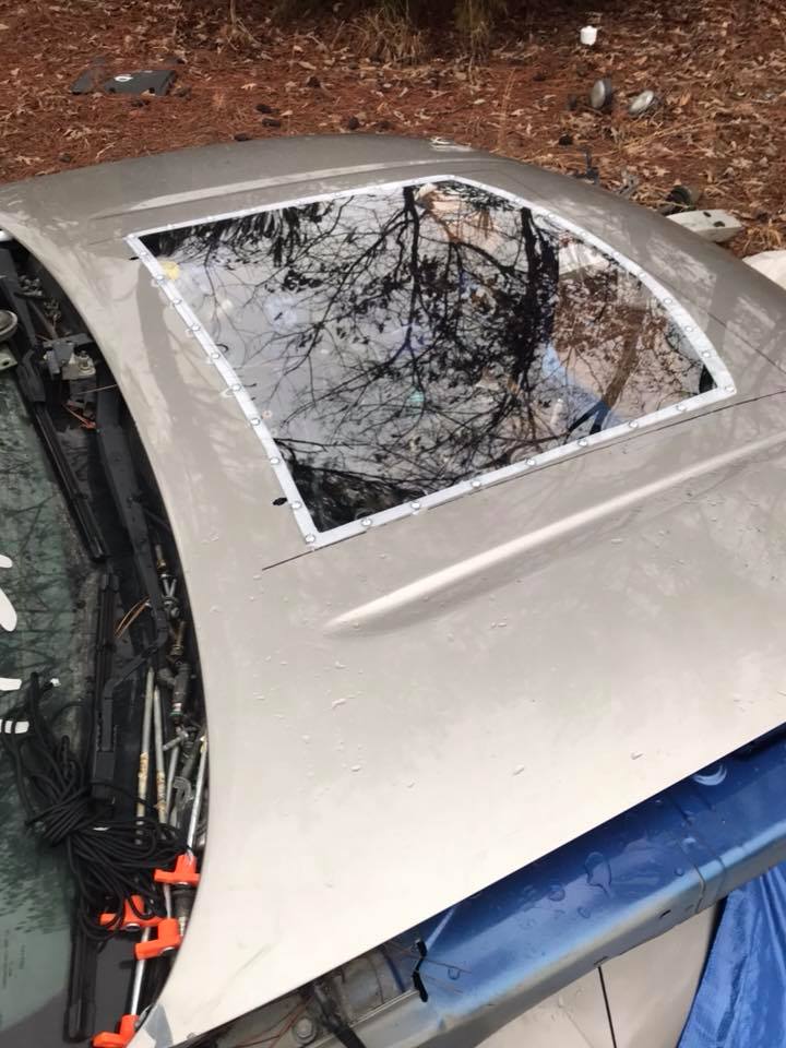
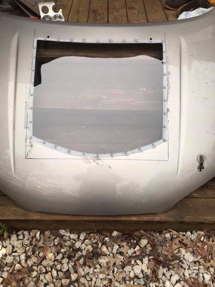
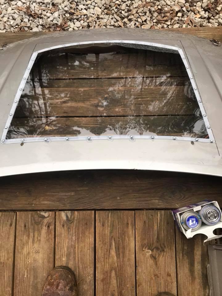
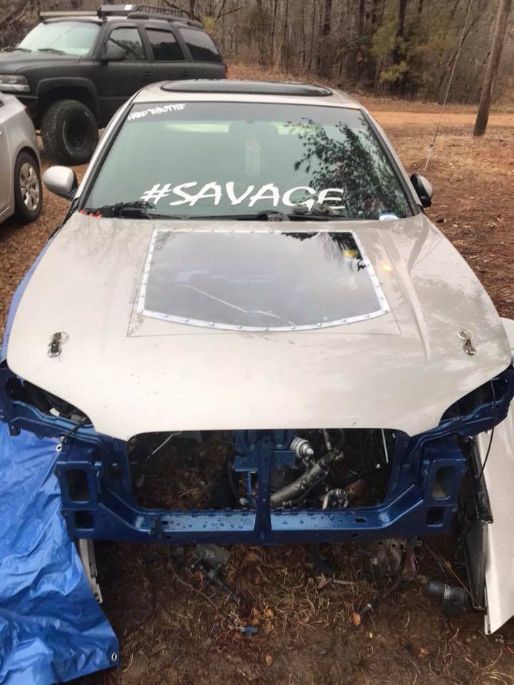
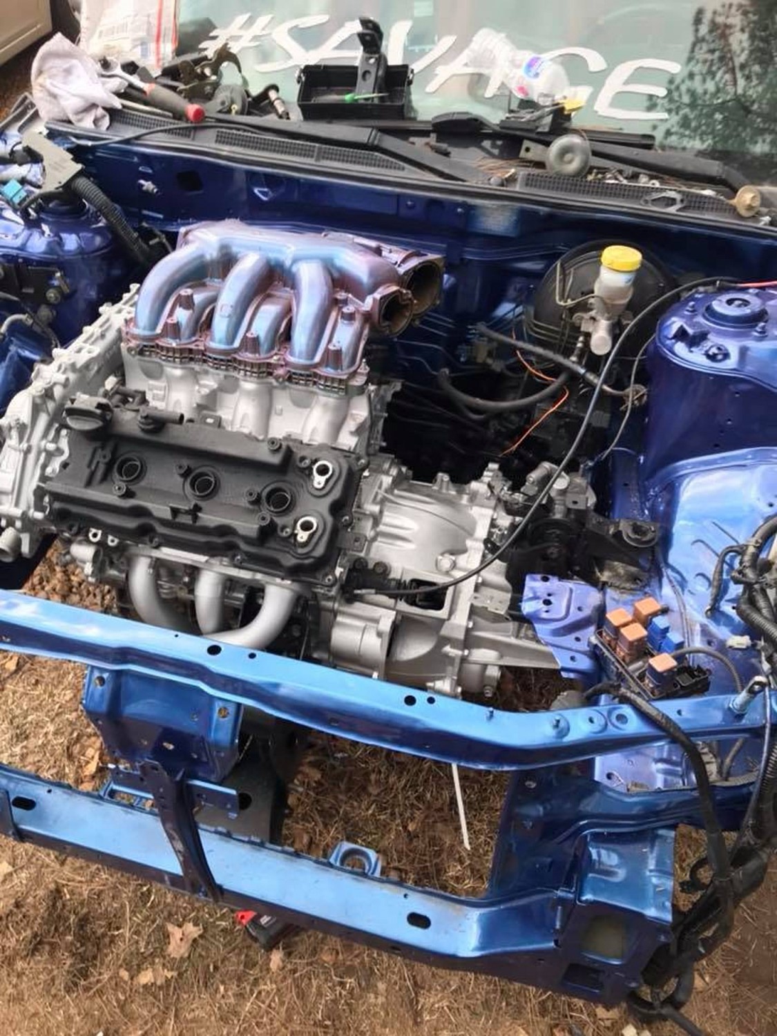
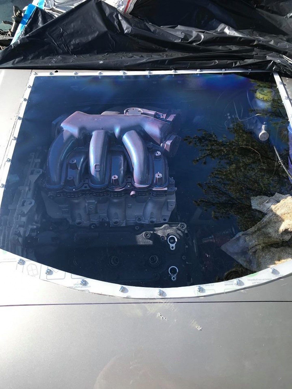
This is a one-of-a-kind custom hood made by Shaquille himself. Definitely very creative and unique. First of its kind on a Nissan Maxima.
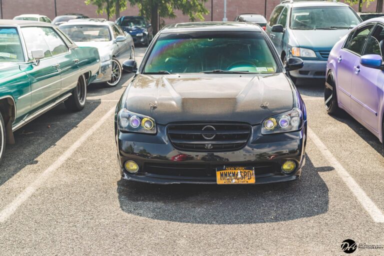
Owner: Stephen Martindale
Year: 2003
Model: Maxima
Color: Black
Transmission: 6-Speed Manual
Trim: SE


Performance:
Interior/Exterior:
Suspension/Wheels/Brakes:

Credit: Mark Baker
**THIS SETUP IS FULLY INDEPENDENT TO A SEPARATE TOGGLE SWITCH, PULLING POWER FROM YOUR AMPS POSITIVE WIRE, IT WILL NOT WORK WITH YOUR SHIFTER**
I only have an HID in the driver’s side. The passenger side is LED which has stock functionality with the shifter. I did this so I wouldn’t have to use the HID every time I back up, every time I shift into Drive causing the ballast to fire up for a split second passing reverse reducing the life span, and to be able to blind tailgaters behind me on the highway. You have no idea how many people get my attention to tell me one of my reverse lights are out. If you decide to do HIDs on both sides then just combine the positives from each ballast and ground negatives on each side near the ballast.
The “Pilot Safety” toggle switch I used had 3 wire connections. If you get a switch with only two connections, then tough titties, you figure out how that shit works, I don’t know, don’t ask me. I used regular speaker wiring (16 or 14 gauge I think, you don’t wanna use anything too small for obvious reasons) and “crimp style” connectors.
Wires will connect from:
Find a suitable place to mount the switch and figure out how to run wires to that location. I put mine where the heated seat switches would be if I had leather, which I don’t. Lucky me because running wires from there was extremely easy, and was an extremely convenient location to hit the switch on the go. I just ran it straight back underneath the center console, through the rear hump on the floor to under the bench seat. Then to the amp/cap and around the “carpet” lining of the trunk.
I pulled power from my Amp/Capacitor wiring which goes directly into the switch. If you don’t have an amp, just run a wire from the battery. This is where you use appropriate sized “crimp style” connectors. You can also use a distributor block to split the amp wire so one goes to the amp and the other goes to the switch. Me being ghetto and cheap, my power wire is connected directly at the positive connection of the capacitor itself. Before I had the capacitor, I had it connected directly to the amps power/positive connection with no problems.
(^HIGHLY RECOMMENDED: Use an “in-line fuse” here BETWEEN the amp and the switch, so you don’t blow the bulb, ballast or switch, due to any spikes or whatever. I think a 10-15amp fuse will suffice but start low, fuses are cheaper to replace. I have one but I haven’t even put it in yet and haven’t encountered any problems thus far. I’m just connected directly.)
Wire comes out of the switch and is grounded to any suitable bolt. Mine is actually grounded at the amps negative terminal, don’t ask me why, it’s probably wasn’t the brightest idea, but I did. (Haven’t encountered any problems yet) Then run a ground from the negative terminal of the ballast to any suitable bolt. (Good, now your nice and grounded)
Comes out of the switch goes straight to the positive connection to the HID Ballast. (Again, appropriate sized “crimp style” connectors were used here on each ends, but your set up may be different, I don’t know know. I’m not there.)
How you fit the bulb into the tail light is all up to you. I got mine from Gregory Lachhman in New York who did his a long time ago. He got an extra Oem bulb socket from the the JY or whatever, drilled a big enough hole through it to fit the bulb, and sealed it in place with JB weld I think. He helped me through this when I did it so credit goes out to him. So my HID bulb is pretty much plug and play. Perfect fit. Although if the bulb blows out, I’m gonna have to find another socket to drill a hole in and fit the bulb.
I used a slim ballast and just used double sticky tape to mount it to the inner fender wall.
My bulb is 6000k.
I’m sure there are many other methods to doing this, but this is how I did it. If this DIY has helped you, please post a pic of your setup and tag me in it. Thanks.

Car Pics:

Credit: Eddy


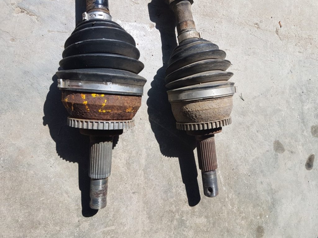
As many of you are aware, Raxles no longer makes axles for Maximas. The best option these days is to go with rebuilt OEM.
2004-2006 6thgen 6-Speed axles will fit in the 2002-2003 5thgens. All you need is the bracket for the passenger side, no other mods required. The 6thgen axles are “beefier” than the 5thgen axles. I definitely consider it an “upgrade” similar to the 5.5 vs 6thgen BBK discussions.
Make sure if you are using a 6thgen axle that you swap the bracket too. At glance, it may look similar but it’s slightly different. If you try to use the 5.5 axle bracket on 6thgen…. you will be doing the job again.


This was the aftermath of my aftermarket Axle before going 6thgen OEM on my 5.5 Supercharged Max. No vibrations at all with the 6thgen Axle.


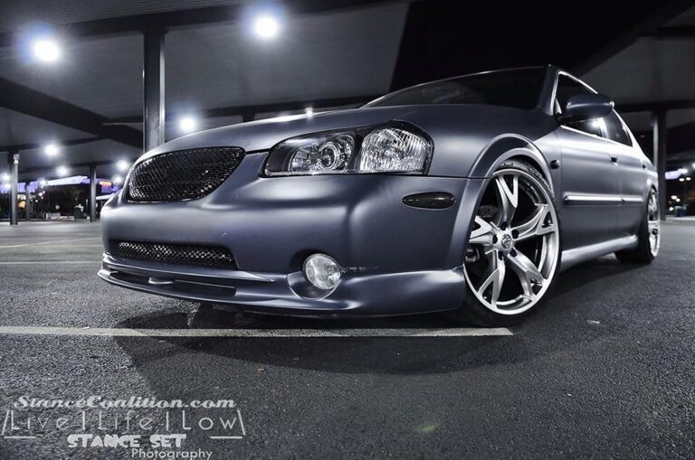
Owner: Ryan Ly
Year: 2001
Model: Maxima
Color: Custom
Transmission: 4-Speed Automatic
Trim: SE


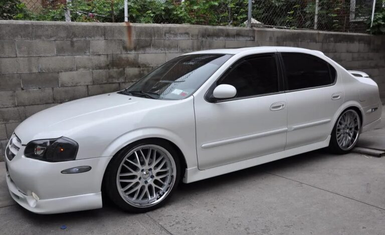
Owner: hollywoood
Year: 2001
Model: Maxima
Color: White
Transmission: 5-Speed Manual
Trim: SE


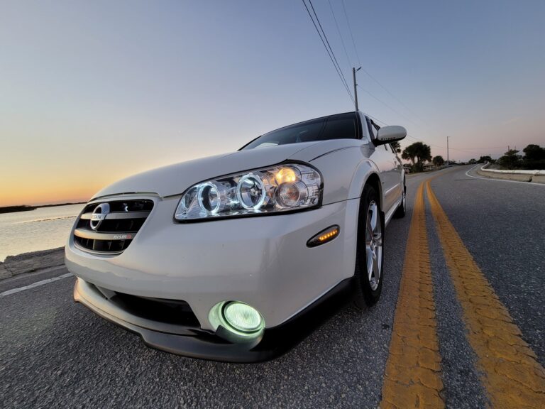
Owner: Dan Walton
Year: 2002
Model: Maxima
Color: White
Transmission: 4-Speed Automatic
Trim: SE


Community Member Credit: Kevin Kryzda

Tools necessary:

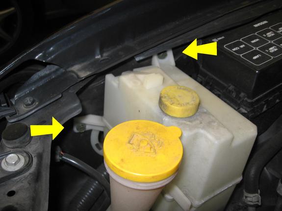
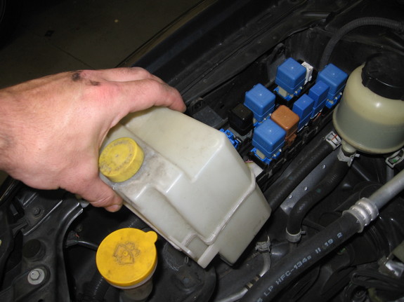

4. Now you will want to remove the air conditioning relay and the heated mirror relay if you are equipped with them. To do this, use your pry tool and insert on the side of the relay that has a clip, push away from the relay and then pull up on the relay itself.


7. Now that you have the wiring exposed you are going to be working with the signal wire from the fog relay and the accessory power wire from the air conditioning relay. The yellow wire coming out of the fog relay is the wire you want to give +12V and the pink wire with a blue stripe from the A/C relay is where you will get it. To access the pink wire better you will probably need to remove the relay harness from the housing. To do this pry in the direction indicated and push out the bottom of the housing.


8. Now cut the yellow wire and without cutting the pink wire run a wire from it to the yellow wire leading into the blue relay harness.
9. I prefer soldering all of my connections but you can attach how you like. I highly recommend no matter what you do though, make sure to tape up everywhere you work. Make sure to tape up the open end of the yellow wire as well.

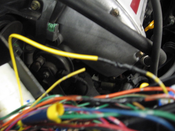
10. Now close everything up and reverse the previous steps to return everything how you found it. Flip your fog lights on and admire. You can turn them on whenever you want granted the car is on.
